EP0950766B1 - Anneau réglable pour couvercles de regard et de bouches d'égout - Google Patents
Anneau réglable pour couvercles de regard et de bouches d'égout Download PDFInfo
- Publication number
- EP0950766B1 EP0950766B1 EP19980119676 EP98119676A EP0950766B1 EP 0950766 B1 EP0950766 B1 EP 0950766B1 EP 19980119676 EP19980119676 EP 19980119676 EP 98119676 A EP98119676 A EP 98119676A EP 0950766 B1 EP0950766 B1 EP 0950766B1
- Authority
- EP
- European Patent Office
- Prior art keywords
- ring
- compensating ring
- compensating
- height
- axis
- Prior art date
- Legal status (The legal status is an assumption and is not a legal conclusion. Google has not performed a legal analysis and makes no representation as to the accuracy of the status listed.)
- Expired - Lifetime
Links
- 239000004033 plastic Substances 0.000 claims description 12
- 229920003023 plastic Polymers 0.000 claims description 12
- 238000010276 construction Methods 0.000 claims description 6
- -1 polypropylene Polymers 0.000 claims description 6
- 239000000463 material Substances 0.000 claims description 5
- 239000004743 Polypropylene Substances 0.000 claims description 4
- 229920001155 polypropylene Polymers 0.000 claims description 4
- OKTJSMMVPCPJKN-UHFFFAOYSA-N Carbon Chemical compound [C] OKTJSMMVPCPJKN-UHFFFAOYSA-N 0.000 claims description 2
- 229910002804 graphite Inorganic materials 0.000 claims description 2
- 239000010439 graphite Substances 0.000 claims description 2
- 125000006850 spacer group Chemical group 0.000 claims 4
- 239000000853 adhesive Substances 0.000 description 6
- 230000001070 adhesive effect Effects 0.000 description 6
- 239000004570 mortar (masonry) Substances 0.000 description 6
- 238000009434 installation Methods 0.000 description 5
- 239000000945 filler Substances 0.000 description 4
- 239000004568 cement Substances 0.000 description 3
- 239000002002 slurry Substances 0.000 description 3
- 230000006378 damage Effects 0.000 description 2
- 238000004519 manufacturing process Methods 0.000 description 2
- 241000909536 Gobiesocidae Species 0.000 description 1
- 206010000496 acne Diseases 0.000 description 1
- 238000001816 cooling Methods 0.000 description 1
- 230000001419 dependent effect Effects 0.000 description 1
- 238000005516 engineering process Methods 0.000 description 1
- 230000002093 peripheral effect Effects 0.000 description 1
- 230000007704 transition Effects 0.000 description 1
Images




Classifications
-
- E—FIXED CONSTRUCTIONS
- E02—HYDRAULIC ENGINEERING; FOUNDATIONS; SOIL SHIFTING
- E02D—FOUNDATIONS; EXCAVATIONS; EMBANKMENTS; UNDERGROUND OR UNDERWATER STRUCTURES
- E02D29/00—Independent underground or underwater structures; Retaining walls
- E02D29/12—Manhole shafts; Other inspection or access chambers; Accessories therefor
- E02D29/124—Shaft entirely made of synthetic material
-
- E—FIXED CONSTRUCTIONS
- E02—HYDRAULIC ENGINEERING; FOUNDATIONS; SOIL SHIFTING
- E02D—FOUNDATIONS; EXCAVATIONS; EMBANKMENTS; UNDERGROUND OR UNDERWATER STRUCTURES
- E02D29/00—Independent underground or underwater structures; Retaining walls
- E02D29/12—Manhole shafts; Other inspection or access chambers; Accessories therefor
- E02D29/14—Covers for manholes or the like; Frames for covers
- E02D29/1409—Covers for manholes or the like; Frames for covers adjustable in height or inclination
Definitions
- the invention is based on a compensation ring according to the preamble of claim 1 and relates to a ring system made of plastic and in particular of polypropylene with the claim to the required inclinations and altitudes for exact edition of the commercially available manhole covers and street inlets in Canal and road construction.
- the minimum thickness of a ring made of concrete - with the diameter of the shaft covers of 625 mm - is at least 5 cm. Since two different inclinations on the road surface must always be set simultaneously - longitudinal and transverse inclination - the combination of FIG. 1 is to be used twice, since only a certain inclination can be achieved with one combination.
- This grouting area is a weak point, which - often clearly visible - is a The shaft cover can be removed.
- the weak point is mostly improper execution - which the creation of voids in Mortar structure cannot be completely excluded - and in the stress caused by Frost. Both result from the enormous load from heavy goods traffic deformation of the mortar in this critical area.
- the manhole cover - more precisely the manhole cover support - sits on the one below stable component.
- the use of a plastic filler as a transition connection between the The uppermost poly ring 101 and the manhole cover 100 provide further advantages in terms of construction time and is provided in the overall system.
- the present invention is based on the object To provide a compensation ring according to the preamble of claim 1, which has the advantages of the compensation ring known from D1 and at the same time is able to hold a manhole cover permanently and at the exact height.
- a compensating ring with the Features of claim 1.
- Such a compensation ring has the essential Advantage that the pimple-like projections drain between Manhole cover and compensating ring to be added adhesive, so in particular of mortar, do not hinder and thus ensure that the manhole cover while displacing the excess adhesive material on the knob-like Protrusions are placed, being in the end position on the adhesive and especially the mortar bed floats, so no more force exerts what a large area of the manhole cover on the adhesive allows.
- the knob-like projections thus guarantee, on the one hand, that the manhole cover actually the projections acted on and rests on them and thus has the required height level and on the other hand that the large area Apply a correspondingly good adhesive bond to the manhole cover on the adhesive results.
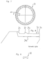
- Fig. 1 The detail shown in Fig. 1 is used to specify the direction of inclination.
- Fig. 4 The detail shown in Fig. 4 is used to display the ring thickness
- 5 serves as a height compensation ring 11.
- the knobs 2, 12 shown in FIGS. 2 and 5 are on the ring surface 1a, 11a suitable for establishing a connection between the rings. So that's one Sufficient stability guaranteed during the installation phase (according to patent claims No. 1, 2, 5, 6). There is no further connecting element between the rings required. Only between the shaft cone 106 made of concrete and the first poly ring 105 (case A) and between the uppermost poly ring 101 and the manhole cover 100 (case B) is a cement slurry connector or a plastic filler is required (see Fig. 24). The strenght this connecting element in case A is about 2 - 3 mm around the unevenness equalize the shaft cone surface. In case B the strength is dependent from the knob height acc. Fig. 2 and 5 and will be approximately 3 mm.
- the knobs 112 provide until the previously described connecting element has hardened the support for the manhole cover 100 ago. See Fig. 24.
- the arrangement of the knobs and their number allows the relative unevenness relativize the underside of the manhole cover.
- cutouts 7 shown in FIGS. 3 and 6 (according to patent claims 5 and 6), 17 on the underside 1b, 11b of the ring 1, 11 serve to reduce the weight and for faster cooling in production.
- the upstands 3, 4, shown in Fig. 2, 3, 5 and 6 (according to claim 1), 13, 14 on the outside and inside of the ring serve on the one hand for the stability of the rings among themselves, on the other hand, the upstands are there for the connecting element between the uppermost ring 112 (see FIG. 24) and the shaft cover 100 introduced cement slurries or the plastic filler as so-called scraper edges to serve. This ensures that the paving thickness is always the same.
- the ring 21 shown in FIGS. 7 and 8 is provided as a system start ring. He is as the top end of the shaft cone 106 made of concrete integrate. As a result, the previously described connecting element is omitted in this area.
- the nap hat 26 shown in FIG. 9 (according to claim 2) enables one Fine alignment on the top ring 112 by placing the components 26 on the Location that does not yet meet the required elevation or slope values.
- the component 26 is non-positively placed on the knobs 112. The cavity between the base of the ring and the lower edge of the manhole cover with the previous already filled cement slurry or the plastic filler, which creates the adhesion.
- the components (31, 41, 51, 61, 71, 81) shown in FIGS. 10 to 23 for the street inlets also get a knob system, which for stability during the Installation phase serves.
- the upstand on the inside and outside of the ring is not required.
- polypropylene in particular is used as the material for the plastic rings comes into question, optionally with the addition of graphite.
Landscapes
- Engineering & Computer Science (AREA)
- Environmental & Geological Engineering (AREA)
- Life Sciences & Earth Sciences (AREA)
- General Life Sciences & Earth Sciences (AREA)
- Mining & Mineral Resources (AREA)
- Paleontology (AREA)
- Civil Engineering (AREA)
- General Engineering & Computer Science (AREA)
- Structural Engineering (AREA)
- Underground Structures, Protecting, Testing And Restoring Foundations (AREA)
Claims (10)
- Anneau de réglage pour couvercles de regards et de bouches d'égout avec notamment un axe de couvercle vertical, l'anneau (1, 11, 21, 31, 41, 51, 61, 71, 81, 101, 102, 103, 104, 105) étant fabriqué en matière plastique, l'anneau de réglage présentant au moins une saillie (2, 3, 4, 12, 13, 14, 22, 23, 24, 112) s'étendant parallèlement à l'axe de l'anneau, la saillie étant constituée d'un bord (3, 4, 13, 14, 23, 24) périphérique extérieur et/ou intérieur et dépassant verticalement, placé sur le côté supérieur (1a, 11a, 21a) de l'anneau de réglage s'étendant, à l'état monté, approximativement dans un niveau horizontal, et l'anneau de réglage (1, 11, 21) présentant un évidement (5, 6, 15, 16) adapté à la position et à la forme de la saillie (3, 4, 13, 14, 23, 24), lequel évidement est prévu notamment sur le côté inférieur (1b, 11b, 21b) de l'anneau de réglage et sert à loger la saillie d'un anneau de réglage placé en-dessous, caractérisé en ce que plusieurs saillies (2, 12, 22, 112) supplémentaires dépassant verticalement sont prévues et sont constituées d'éléments d'espacement (2, 12, 22, 112), formés comme des boutons, répartis sur-le côté supérieur (1a, 11a, 21a) de l'anneau de réglage, et forment un appui à distance du côté supérieur pour un anneau (100) à disposer au-dessus.
- Anneau de réglage selon au moins la revendication 1, caractérisé en ce que les éléments d'espacement (2, 12, 22) peuvent être raccordés par conjonction de forme à des éléments d'espacement supplémentaires (26) pour modifier le niveau en hauteur de la surface d'appui.
- Anneau de réglage selon la revendication 1, caractérisé en ce que la matière plastique est composée au moins en partie de matériaux recyclés.
- Anneau de réglage selon au moins l'une des revendications précédentes, caractérisé en ce que la matière plastique est composée essentiellement de polypropylène, notamment mélangé à du graphite.
- Anneau de réglage selon au moins l'une des revendications précédentes, caractérisé en ce que l'anneau de réglage (1, 11) présente sur son côté inférieur (1b, 11b) au moins un, et notamment plusieurs évidements (7, 17) supplémentaires répartis sur le côté inférieur.
- Anneau de réglage selon au moins la revendication 5, caractérisé en ce que l'évidement supplémentaire est au moins positionné et formé de telle sorte que les parties de l'anneau de réglage qui en restent présentent une épaisseur de paroi essentiellement similaire.
- Anneau de réglage selon au moins l'une des revendications précédentes, caractérisé en ce que l'anneau de réglage (11, 51, 81) est muni de côtés supérieur et inférieur (11a, 11b) s'étendant essentiellement parallèlement l'un par rapport à l'autre et essentiellement perpendiculairement à l'axe de l'anneau pour utilisation comme anneau de réglage en hauteur.
- Anneau de réglage selon au moins l'une des revendications précédentes, caractérisé en ce que l'anneau de réglage (1, 31, 41, 61, 71) est muni de côtés supérieur et inférieur (1a, 1b) passant de manière essentiellement adaptée l'un par rapport à l'autre pour utilisation comme anneau de réglage d'inclinaison, et en ce que l'inclinaison entre le côté supérieur et le côté inférieur se monte environ entre un et dix pour cent.
- Anneau de réglage selon au moins la revendication 8, caractérisé en ce que le côté inférieur (1b) de l'anneau de réglage d'inclinaison (11, 31, 41, 61, 71) est essentiellement perpendiculaire à l'axe de l'anneau et le côté supérieur (1a) présente une inclinaison d'environ un à dix pour cent à l'opposé de la perpendiculaire de l'axe de l'anneau.
- Système d'anneau de réglage pour le réglage en hauteur et/ou de l'inclinaison, composé d'au moins deux anneaux de réglage (101, 102, 103, 104, 105) placés l'un au-dessus de l'autre selon au moins l'une des revendications précédentes.
Applications Claiming Priority (4)
| Application Number | Priority Date | Filing Date | Title |
|---|---|---|---|
| DE19816559A DE19816559A1 (de) | 1998-04-15 | 1998-04-15 | Ausgleichsringsystem zur Höhen- u. Neigungsanpassung von zylindrischen und quadratischen Schachtoberteilen im Kanalbau |
| DE19816559 | 1998-04-15 | ||
| DE19844247 | 1998-09-26 | ||
| DE19844247 | 1998-09-26 |
Publications (2)
| Publication Number | Publication Date |
|---|---|
| EP0950766A1 EP0950766A1 (fr) | 1999-10-20 |
| EP0950766B1 true EP0950766B1 (fr) | 2002-04-17 |
Family
ID=26045479
Family Applications (1)
| Application Number | Title | Priority Date | Filing Date |
|---|---|---|---|
| EP19980119676 Expired - Lifetime EP0950766B1 (fr) | 1998-04-15 | 1998-10-17 | Anneau réglable pour couvercles de regard et de bouches d'égout |
Country Status (1)
| Country | Link |
|---|---|
| EP (1) | EP0950766B1 (fr) |
Families Citing this family (4)
| Publication number | Priority date | Publication date | Assignee | Title |
|---|---|---|---|---|
| DE10061823C1 (de) * | 2000-12-12 | 2002-10-10 | Ahlmann Aco Severin | Schacht- bzw. Strassenablauf |
| DE20303646U1 (de) * | 2003-02-27 | 2004-07-15 | Eberle, Bernd | Schachtring sowie Schacht |
| NZ590938A (en) | 2011-02-04 | 2013-08-30 | Opus Internat Consultants Ltd | Improvements to adjustable supports for access hatch frames |
| EP3910120A1 (fr) * | 2020-05-14 | 2021-11-17 | Funke Kunststoffe GmbH | Plaque de compensation et partie supérieure d'une bouche d'égout |
Family Cites Families (6)
| Publication number | Priority date | Publication date | Assignee | Title |
|---|---|---|---|---|
| DE3123373A1 (de) | 1981-06-12 | 1983-05-11 | Joachim Ing.(grad.) 3405 Rosdorf Rinne | Ausgleichsringsystem zur hoehen- und neigungsanpassung von zylindrischen schachtoberteilen |
| DE3503855A1 (de) * | 1985-02-05 | 1986-08-07 | Carl Dan. Peddinghaus Gmbh & Co Kg, 5828 Ennepetal | Verwendung von graphit als zusatzstoff fuer modellkunststoffe, modellmaterial sowie formenschleifverfahren |
| US5564855A (en) * | 1994-05-31 | 1996-10-15 | National Polymers Inc | Height adjustment ring for manhole cover frame |
| US5470172A (en) * | 1994-06-06 | 1995-11-28 | Wiedrich; Dwight G. | Manhole adjusting extension ring section |
| US5482400A (en) * | 1994-10-03 | 1996-01-09 | National Rubber Technology Inc. | Segmented adjustment riser |
| US5513926A (en) * | 1995-03-27 | 1996-05-07 | Prescott; Alain | Manhole head assembly |
-
1998
- 1998-10-17 EP EP19980119676 patent/EP0950766B1/fr not_active Expired - Lifetime
Also Published As
| Publication number | Publication date |
|---|---|
| EP0950766A1 (fr) | 1999-10-20 |
Similar Documents
| Publication | Publication Date | Title |
|---|---|---|
| DE69827290T2 (de) | Vorrichtung zum Einstellen der Neigung der Oberfläche einer Konstruktion auf Stützfüßen | |
| DE3218329A1 (de) | System von vorgefertigten betonelementen fuer den bau von wegen | |
| EP0950766B1 (fr) | Anneau réglable pour couvercles de regard et de bouches d'égout | |
| DE102018103201A1 (de) | Verbauvorrichtung | |
| EP0024736A1 (fr) | Revêtement d'aire de roulement en éléments assemblés entre eux | |
| EP3075908B1 (fr) | Rainure de fente | |
| DE202012102396U1 (de) | Fugenprofil und Anordnung aus mehreren Fugenprofilen für Fugen in einem Betonbelag | |
| EP2392732B1 (fr) | Système de pontage pour joints de dilatation | |
| EP1293606B1 (fr) | Dispositif de coffrage journalier | |
| DE4329652A1 (de) | Verfahren und Anordnung zum Befestigen eines Einbauteiles in einer Straße | |
| EP3480368A1 (fr) | Système de revêtement de plaques destiné à la fabrication d'une construction de soutènement ou d'une construction de talus raide | |
| WO2010075855A1 (fr) | Système de goujon pour construction en béton | |
| DE202019106295U1 (de) | Schachtdeckel-Umrandungsplatte | |
| DE19541694C2 (de) | Vorrichtung zum Erstellen von Stelzen für stelzenverlegte Plattenbeläge auf Böden | |
| AT522089B1 (de) | Höhenverstellbares Schachtringelement | |
| DE7420715U (de) | Bauelement für Stützmauern | |
| DE2849168A1 (de) | Vorrichtung zur ausgerichteten halterung von platten | |
| DE4004851A1 (de) | Begrenzungspfosten mit spezialbodenanker | |
| EP2915920B1 (fr) | Procédé pour la pose de revêtements de sol limités en surface | |
| EP3967827B1 (fr) | Partie de marche d'escalier préfabriqué en béton | |
| DE2748974C3 (de) | Höhenausgleichsvorrichtung für einen Einsteigschacht | |
| DE102020210009B3 (de) | Fahrbahnübergangskonstruktion, modulares System zur Überbrückung einer Bauwerksfuge, Verfahren zur Montage einer Fahrbahnübergangskonstruktion und Verfahren zum Öffnen einer Solchen | |
| EP3205776B1 (fr) | Installation sur une chaussée et procédé de faire une installation sur unce chaussée | |
| DE3519108A1 (de) | Wasserablaufrinne | |
| DE102023108359A1 (de) | Thermisch isolierendes Bauelement, Gebäudeabschnitt und Verfahren zum Einbau eines thermisch isolierenden Bauelementes |
Legal Events
| Date | Code | Title | Description |
|---|---|---|---|
| PUAI | Public reference made under article 153(3) epc to a published international application that has entered the european phase |
Free format text: ORIGINAL CODE: 0009012 |
|
| AK | Designated contracting states |
Kind code of ref document: A1 Designated state(s): AT BE CH DE DK ES FR GB IT LI NL PT SE |
|
| AX | Request for extension of the european patent |
Free format text: AL;LT;LV;MK;RO;SI |
|
| 17P | Request for examination filed |
Effective date: 20000418 |
|
| AKX | Designation fees paid |
Free format text: AT CH DE DK ES GB IT LI NL PT SE |
|
| RBV | Designated contracting states (corrected) |
Designated state(s): AT BE CH DE DK ES FR GB IT LI NL PT SE |
|
| 17Q | First examination report despatched |
Effective date: 20000803 |
|
| GRAG | Despatch of communication of intention to grant |
Free format text: ORIGINAL CODE: EPIDOS AGRA |
|
| GRAG | Despatch of communication of intention to grant |
Free format text: ORIGINAL CODE: EPIDOS AGRA |
|
| GRAH | Despatch of communication of intention to grant a patent |
Free format text: ORIGINAL CODE: EPIDOS IGRA |
|
| GRAH | Despatch of communication of intention to grant a patent |
Free format text: ORIGINAL CODE: EPIDOS IGRA |
|
| REG | Reference to a national code |
Ref country code: GB Ref legal event code: IF02 |
|
| GRAA | (expected) grant |
Free format text: ORIGINAL CODE: 0009210 |
|
| AK | Designated contracting states |
Kind code of ref document: B1 Designated state(s): AT BE CH DE DK ES FR GB IT LI NL PT SE |
|
| PG25 | Lapsed in a contracting state [announced via postgrant information from national office to epo] |
Ref country code: IT Free format text: LAPSE BECAUSE OF FAILURE TO SUBMIT A TRANSLATION OF THE DESCRIPTION OR TO PAY THE FEE WITHIN THE PRESCRIBED TIME-LIMIT;WARNING: LAPSES OF ITALIAN PATENTS WITH EFFECTIVE DATE BEFORE 2007 MAY HAVE OCCURRED AT ANY TIME BEFORE 2007. THE CORRECT EFFECTIVE DATE MAY BE DIFFERENT FROM THE ONE RECORDED. Effective date: 20020417 Ref country code: GB Free format text: LAPSE BECAUSE OF FAILURE TO SUBMIT A TRANSLATION OF THE DESCRIPTION OR TO PAY THE FEE WITHIN THE PRESCRIBED TIME-LIMIT Effective date: 20020417 |
|
| REF | Corresponds to: |
Ref document number: 216450 Country of ref document: AT Date of ref document: 20020515 Kind code of ref document: T |
|
| REG | Reference to a national code |
Ref country code: CH Ref legal event code: EP |
|
| REF | Corresponds to: |
Ref document number: 59803844 Country of ref document: DE Date of ref document: 20020523 |
|
| PG25 | Lapsed in a contracting state [announced via postgrant information from national office to epo] |
Ref country code: SE Free format text: LAPSE BECAUSE OF FAILURE TO SUBMIT A TRANSLATION OF THE DESCRIPTION OR TO PAY THE FEE WITHIN THE PRESCRIBED TIME-LIMIT Effective date: 20020717 Ref country code: PT Free format text: LAPSE BECAUSE OF FAILURE TO SUBMIT A TRANSLATION OF THE DESCRIPTION OR TO PAY THE FEE WITHIN THE PRESCRIBED TIME-LIMIT Effective date: 20020717 Ref country code: DK Free format text: LAPSE BECAUSE OF FAILURE TO SUBMIT A TRANSLATION OF THE DESCRIPTION OR TO PAY THE FEE WITHIN THE PRESCRIBED TIME-LIMIT Effective date: 20020717 |
|
| ET | Fr: translation filed | ||
| GBV | Gb: ep patent (uk) treated as always having been void in accordance with gb section 77(7)/1977 [no translation filed] |
Effective date: 20020417 |
|
| PG25 | Lapsed in a contracting state [announced via postgrant information from national office to epo] |
Ref country code: AT Free format text: LAPSE BECAUSE OF NON-PAYMENT OF DUE FEES Effective date: 20021017 |
|
| PG25 | Lapsed in a contracting state [announced via postgrant information from national office to epo] |
Ref country code: ES Free format text: LAPSE BECAUSE OF FAILURE TO SUBMIT A TRANSLATION OF THE DESCRIPTION OR TO PAY THE FEE WITHIN THE PRESCRIBED TIME-LIMIT Effective date: 20021030 |
|
| PG25 | Lapsed in a contracting state [announced via postgrant information from national office to epo] |
Ref country code: LI Free format text: LAPSE BECAUSE OF NON-PAYMENT OF DUE FEES Effective date: 20021031 Ref country code: CH Free format text: LAPSE BECAUSE OF NON-PAYMENT OF DUE FEES Effective date: 20021031 Ref country code: BE Free format text: LAPSE BECAUSE OF NON-PAYMENT OF DUE FEES Effective date: 20021031 |
|
| PLBE | No opposition filed within time limit |
Free format text: ORIGINAL CODE: 0009261 |
|
| STAA | Information on the status of an ep patent application or granted ep patent |
Free format text: STATUS: NO OPPOSITION FILED WITHIN TIME LIMIT |
|
| 26N | No opposition filed |
Effective date: 20030120 |
|
| BERE | Be: lapsed |
Owner name: *KLEIN WALTER Effective date: 20021031 |
|
| PG25 | Lapsed in a contracting state [announced via postgrant information from national office to epo] |
Ref country code: NL Free format text: LAPSE BECAUSE OF NON-PAYMENT OF DUE FEES Effective date: 20030501 |
|
| REG | Reference to a national code |
Ref country code: CH Ref legal event code: PL |
|
| NLV4 | Nl: lapsed or anulled due to non-payment of the annual fee |
Effective date: 20030501 |
|
| PGFP | Annual fee paid to national office [announced via postgrant information from national office to epo] |
Ref country code: FR Payment date: 20041019 Year of fee payment: 7 |
|
| PGFP | Annual fee paid to national office [announced via postgrant information from national office to epo] |
Ref country code: DE Payment date: 20060428 Year of fee payment: 8 |
|
| PG25 | Lapsed in a contracting state [announced via postgrant information from national office to epo] |
Ref country code: FR Free format text: LAPSE BECAUSE OF NON-PAYMENT OF DUE FEES Effective date: 20060630 |
|
| REG | Reference to a national code |
Ref country code: FR Ref legal event code: ST Effective date: 20060630 |
|
| PG25 | Lapsed in a contracting state [announced via postgrant information from national office to epo] |
Ref country code: DE Free format text: LAPSE BECAUSE OF NON-PAYMENT OF DUE FEES Effective date: 20070501 |