EP0950785A1 - Verriegelungsbeschlag mit mindestens zwei Riegeln für Schiebetür, Schiebefenster oder ähnliches - Google Patents
Verriegelungsbeschlag mit mindestens zwei Riegeln für Schiebetür, Schiebefenster oder ähnliches Download PDFInfo
- Publication number
- EP0950785A1 EP0950785A1 EP99400734A EP99400734A EP0950785A1 EP 0950785 A1 EP0950785 A1 EP 0950785A1 EP 99400734 A EP99400734 A EP 99400734A EP 99400734 A EP99400734 A EP 99400734A EP 0950785 A1 EP0950785 A1 EP 0950785A1
- Authority
- EP
- European Patent Office
- Prior art keywords
- auxiliary
- chamber
- profile
- front wall
- light
- Prior art date
- Legal status (The legal status is an assumption and is not a legal conclusion. Google has not performed a legal analysis and makes no representation as to the accuracy of the status listed.)
- Granted
Links
Images


Classifications
-
- E—FIXED CONSTRUCTIONS
- E05—LOCKS; KEYS; WINDOW OR DOOR FITTINGS; SAFES
- E05B—LOCKS; ACCESSORIES THEREFOR; HANDCUFFS
- E05B65/00—Locks or fastenings for special use
- E05B65/08—Locks or fastenings for special use for sliding wings
- E05B65/087—Locks or fastenings for special use for sliding wings the bolts sliding parallel to the wings
-
- E—FIXED CONSTRUCTIONS
- E05—LOCKS; KEYS; WINDOW OR DOOR FITTINGS; SAFES
- E05C—BOLTS OR FASTENING DEVICES FOR WINGS, SPECIALLY FOR DOORS OR WINDOWS
- E05C9/00—Arrangements of simultaneously actuated bolts or other securing devices at well-separated positions on the same wing
- E05C9/02—Arrangements of simultaneously actuated bolts or other securing devices at well-separated positions on the same wing with one sliding bar for fastening when moved in one direction and unfastening when moved in opposite direction; with two sliding bars moved in the same direction when fastening or unfastening
- E05C9/026—Arrangements of simultaneously actuated bolts or other securing devices at well-separated positions on the same wing with one sliding bar for fastening when moved in one direction and unfastening when moved in opposite direction; with two sliding bars moved in the same direction when fastening or unfastening comprising key-operated locks, e.g. a lock cylinder to drive auxiliary deadbolts or latch bolts
-
- E—FIXED CONSTRUCTIONS
- E05—LOCKS; KEYS; WINDOW OR DOOR FITTINGS; SAFES
- E05C—BOLTS OR FASTENING DEVICES FOR WINGS, SPECIALLY FOR DOORS OR WINDOWS
- E05C9/00—Arrangements of simultaneously actuated bolts or other securing devices at well-separated positions on the same wing
- E05C9/18—Details of fastening means or of fixed retaining means for the ends of bars
- E05C9/1825—Fastening means
- E05C9/1833—Fastening means performing sliding movements
- E05C9/185—Fastening means performing sliding movements parallel with actuating bar
-
- E—FIXED CONSTRUCTIONS
- E05—LOCKS; KEYS; WINDOW OR DOOR FITTINGS; SAFES
- E05C—BOLTS OR FASTENING DEVICES FOR WINGS, SPECIALLY FOR DOORS OR WINDOWS
- E05C9/00—Arrangements of simultaneously actuated bolts or other securing devices at well-separated positions on the same wing
- E05C9/22—Guides for sliding bars, rods or cables
-
- E—FIXED CONSTRUCTIONS
- E05—LOCKS; KEYS; WINDOW OR DOOR FITTINGS; SAFES
- E05B—LOCKS; ACCESSORIES THEREFOR; HANDCUFFS
- E05B63/00—Locks or fastenings with special structural characteristics
- E05B63/0056—Locks with adjustable or exchangeable lock parts
-
- Y—GENERAL TAGGING OF NEW TECHNOLOGICAL DEVELOPMENTS; GENERAL TAGGING OF CROSS-SECTIONAL TECHNOLOGIES SPANNING OVER SEVERAL SECTIONS OF THE IPC; TECHNICAL SUBJECTS COVERED BY FORMER USPC CROSS-REFERENCE ART COLLECTIONS [XRACs] AND DIGESTS
- Y10—TECHNICAL SUBJECTS COVERED BY FORMER USPC
- Y10T—TECHNICAL SUBJECTS COVERED BY FORMER US CLASSIFICATION
- Y10T292/00—Closure fasteners
- Y10T292/08—Bolts
- Y10T292/0801—Multiple
- Y10T292/0807—Sliding and hooked end
-
- Y—GENERAL TAGGING OF NEW TECHNOLOGICAL DEVELOPMENTS; GENERAL TAGGING OF CROSS-SECTIONAL TECHNOLOGIES SPANNING OVER SEVERAL SECTIONS OF THE IPC; TECHNICAL SUBJECTS COVERED BY FORMER USPC CROSS-REFERENCE ART COLLECTIONS [XRACs] AND DIGESTS
- Y10—TECHNICAL SUBJECTS COVERED BY FORMER USPC
- Y10T—TECHNICAL SUBJECTS COVERED BY FORMER US CLASSIFICATION
- Y10T292/00—Closure fasteners
- Y10T292/08—Bolts
- Y10T292/0911—Hooked end
- Y10T292/0921—Multiple head
Definitions
- the present invention relates to a lock locking at least two locking bolts, to sliding door, window, French window or similar.
- the present invention relates to a fitting comprising an assembly sliding which is movable inside and in the longitudinal direction of a profile chamber constituting the front amount of the opening, and which includes a bolt holder, the opening of which is located opposite a first corresponding light formed in the front wall of said chamber, is adapted to receive, if necessary, in an adjustable manner, the tail of a bolt introduced from outside of said chamber.
- each auxiliary bolt is mounted on a mobile support block inside the profile chamber and also driven by a rod movable inside the profile chamber.
- Each support block is held against the wall front of the room by a plate fixed to said wall by screws which pass through provided lights in the rod.
- Each plate has a large light dimension for passage and sliding of the block corresponding support.
- each plate for the moving the support block considerably weakens the resistance that said wafer can offer in the event of attempted break-in against the corresponding bolt.
- the object of the present invention is to remedy to the disadvantages of known systems and to propose a locking fitting of the aforementioned type which is robust, reliable, economical, and can be implemented place as well when installing equipment new than during modernization of old equipment any with a minimum of easements and costs.
- the locking fitting of the aforementioned type comprises at least one auxiliary box suitable to be inserted inside the chamber of the profile and to be fixed directly on the face interior of the front wall of said chamber by its front wall which has a light similar to said second corresponding light and which includes means for resting on said inner face around said second light, and in that said auxiliary box has an interior cavity suitable for slidingly receiving said bolt holder auxiliary, the interior cavity presenting on its interior surface and auxiliary latch holder having conformations on its outer surface respective complementary extending in the direction longitudinal and in the transverse direction of the front wall of the profile chamber and adapted to cooperate with each other to ensure the guiding the auxiliary bolt holder in the direction longitudinal and maintaining the bolt holder in said cavity.
- the auxiliary box which is fixed directly on the inside of the front wall of the room, can easily be designed to support by itself and transmit in good conditions to the front wall of the profile the forces transmitted to the bolt corresponding assistant in the event of an assault attempt on said bolt.
- the problems of fixing the housing auxiliary against the front wall of the chamber can be adjusted without taking into account the auxiliary bolt holder.
- the auxiliary box comprises a body having in cross section a section substantially in U-shaped and surrounding an interior cavity, and a cover adapted to be fixed to the body to close substantially said interior cavity after introduction of the auxiliary bolt holder inside said cavity.
- the auxiliary box is thus prepared and prefabricated in advance, which limits the number of components that installers must handle and set up on the installation site of a sliding door.
- the front wall of the body adapted to be fixed against the inner face of the front wall of the chamber is opposite the cover, and the cover has two respective sockets internally threaded adapted to receive screws introduced from outside the chamber through holes in the front wall of said chamber to fix the body against said front wall of said chamber.
- the operating rod is adapted to be introduced inside the chamber and extends parallel to the side faces of the chamber.
- the auxiliary bolt holder has a general shape of a flat elongated rod carrying in protruding on one of its main faces a block of material inside which the opening is made said auxiliary latch holder, and the opening of the latch holder auxiliary leads to a notch in one at least, which acts as the front wall of the housing auxiliary, side walls of the body of said housing.
- this one also relates to an auxiliary box adapted to slidingly receive an auxiliary bolt holder suitable for receiving an auxiliary bolt itself.
- this auxiliary unit is characterized in that it is suitable for equipping a fitting according to the first aspect of the invention.
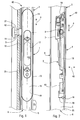
- FIG. 1 Schematically shown in Figures 1 and 2 a control assembly 1 for a fitting 40 of locking of a sliding leaf, shown diagrammatically in 2, door, window, French window or the like.
- This assembly 1 comprises a sliding assembly 3 which is movable inside and in the direction longitudinal 4 of a chamber 5 of the profile 6 constituting the front upright of the sash 2.
- the sliding assembly 3 comprises a bolt holder 7 whose opening 8, located opposite a first corresponding light 9 formed in the front wall 10 of the chamber 5 constituting the edge of the profile 6, is adapted to receive, if necessary in an adjustable manner, the tail 11 of a bolt 12 introduced from the outside from room 5.
- the sliding assembly 3 slides in direction 4 inside a case 13 which is introduced inside the chamber 5 by a light 14 formed on the inner wall 15 forming the inner facade of profile 6, that is to say the wall facing the interior of the room which is closed by the opening 2.
- the housing 13 is integral with a plate of cleanliness 16 which covers the light 14 and which presents itself a light 17 allowing access to an organ maneuver 18 for moving the assembly sliding 3 in one direction or the other.
- assembly 1 is fixed to the longitudinal ends of the light 14 by through two fasteners 19 and 20 arranged in such a way that assembly 1 can be snapped onto the edges of the light 14.
- the fastening elements 19 and 20 are by example the fasteners described in the request French Patent No. 97,04065 in the name of the Applicant.
- Assembly 1 could also be subject on the edges of the light 14 through conventional fasteners that you can insert with assembly 1 inside the chamber and which is then subject to the edges longitudinal of light 14 by screws passing through the cleanliness plate 16.
- Assembly 1 can thus be introduced to the interior of chamber 5 by the single light 14 ce which makes it difficult, if not impossible, to unite the sliding assembly 3 with a rod introduced by elsewhere inside said chamber 5.
- the sliding assembly 3 is connected so sliding, by an operating rod 21 extending in the longitudinal direction 4 of the profile 6, to at at least one auxiliary bolt holder 22 whose opening 23, located opposite a second corresponding light 24 formed in the front wall 10 of the chamber 5, is adapted to receive, if necessary in an adjustable manner, the tail 25 of an auxiliary bolt 26.
- the rod 21 is placed outside of chamber 5, in before and near the front wall 10 thereof.
- the rod 21 thus comprises a first hole 27 for the passage of the tail 11 of the bolt 12, and a second hole 28 for the passage of the tail 25 of the auxiliary bolt 26.
- the profile 6 is shaped so that its inner wall 15 and its outer wall 29 each extend in the direction of arrow 30 towards the front beyond the front wall 10 of the chamber 5 by sails 31, 32 which each have a rib 33, 34 extending parallel to the front wall 10 in the longitudinal direction 4 of the profile 6.
- the ribs 33, 34 define guide means adapted to receive the lateral edges 35, 36 of the rod 21 or of all elongate element integral with said rod 21 (see figure 9).
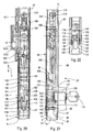
- the following lock fitting 40 the invention comprises in addition to assembly 1 at least an auxiliary box 41 adapted to be introduced to inside chamber 5 of profile 6 and to be fixed directly on the inner face 42 of the front wall 10 of chamber 5 by its front wall 43 which has a light 44 located opposite said second light 24 corresponding and which includes means for build on said inner face 42 around said second light 24.
- the auxiliary unit 41 further comprises a interior cavity 45 adapted to receive so sliding the auxiliary bolt holder 22.
- the inner cavity 45 present on its inner surface
- the auxiliary bolt holder 22 present on its surface exterior, respective conformations complementary 46, 47 extending in the direction longitudinal 4 and in transverse direction 48 of the front wall 10 of the chamber 5 of the profile 6 and adapted to cooperate with each other to guiding the auxiliary bolt holder 22 in the longitudinal direction 4 and holding the bolt holder 22 in said interior cavity 45.
- the auxiliary unit 41 comprises a body 49 having in cross section a section substantially U-shaped and surrounding said cavity interior 45 and a cover 50 adapted to be fixed to the body 49 for substantially closing said cavity interior 45 after introduction of the bolt holder auxiliary 22 inside said cavity 45.
- the operating rod 21 is adapted to be slidingly attached to the outside of the chamber 5 of profile 6, between the front wall 10 and the ribs longitudinal 33 and 34 of profile 6.
- the cover 50 has two respective sockets 51 projecting from the side of the body 50 along it.
- Sockets 51 are internally threaded and are suitable for receiving screws 52 introduced from outside the chamber 5 to through holes 53 in the front wall 10 of said chamber 5 for fixing the body 49 against said wall before 10 of said chamber 5.
- the cover 50 presses the body 49 and in particular the front wall 43 thereof against the inner face 42 of the wall before 10.
- the body 49 and the cover 50 include respective means 57, 58 complementary to each other can snap the cover 50 onto the body 49.
- the cover 50 has two legs elastic bands 58 each carrying a protruding lug 58a suitable for engaging with a complementary lug 57a corresponding to a lug 57 of the body 49 of the housing 41.
- the front wall 43 of the auxiliary housing 41 includes a central region 59 projecting toward the exterior, of exterior contour corresponding to the inner outline of the second light 24 to make protrudes through said light 24, and, on either side on the other side of said region 59, two shoulders 60 extending in the longitudinal direction 4 of the profile 6 and adapted to bear against the inner face 42 of the front wall 10 of the profile 6.
- the auxiliary unit 41 can be inserted in chamber 5 of profile 6 through a light located anywhere on the front wall 10 profile 6, and be moved in chamber 5 to what it looks like in front of the light 24.
- At least one of the screws 52 for fixing the housing auxiliary 41 on the front wall 10 can be a screw needle 52a adapted to bear on the face interior 61 of the rear wall 62 of the chamber 5 of the profile 6.
- the needle screw 52a presses the cover 50 against the body 49 of the auxiliary unit 41, and said body 49 against the inner face 42 of the front wall 10 of profile 6, bearing on the rear wall 62 of chamber 5, while an ordinary screw 52 with head milled is supported on the front wall 10 of said profile 6 for the same function.
- the auxiliary box 41 is fixed by two needle screws 52a, and the central region 59 of the front wall 43 includes the two legs 55.
- the needle screws 52a are introduced by light 24.
- the screw shown at the bottom of these two Figures is a needle screw 52a bearing against the rear wall 62 of chamber 5.
- the screw located in the part upper of these two figures is a conventional screw 52 with countersunk head which passes through a hole 53 in the front wall 10 and a hole 54 of the corresponding tab 55 which is shaped to fit under the front wall 10 to the transverse edge 56 of the light 24.
- the auxiliary box 41 present, preferably on its cover 50, lateral elastic tabs 63 for take support on the side walls 64, 65 of the chamber 5 in order to center the auxiliary box 41 in the transverse direction 48 of the front wall 10 to inside the room 5.
- the cover 50 of the auxiliary box 41 advantageously also has legs rear elastic 66 to bear on the wall rear 62 of room 5.
- auxiliary boxes 41 can be easily placed inside the room either when installing the sliding sash corresponding with its fitting, either during the transformation of an existing fitting to equip it with several auxiliary bolts to strengthen the resistance of this fitting in the event of an attempt of break-in.
- Profile 6 does not need to have the structure shown in Figures 7 to 9.
- the operating rod 21 driven by the main bolt 12 can cause the auxiliary bolts 26 integral with their bolt holder respective auxiliary 22.
- the forces transmitted to the auxiliary bolts 26 are absorbed by the auxiliary unit 41 corresponding and retransmitted by it either to the wall before 10 alone, or at the same time at the front wall 10 and to the rear wall 62 of the profile.
- the conformations 46 of the interior surface of the cavity 45 are formed by two shoulders 46 arranged in transverse direction 48 and extending in the longitudinal direction 4 of the profile 6.
- the conformations 47 of the external surface of the bolt holder 22 are made up of additional shoulders 47 arranged in the same transverse direction 48 and extending in the same longitudinal direction 4.
- the auxiliary bolt holder 22 has a rib 67 projecting in transverse direction 48 and extending in the longitudinal direction 4. This rib 67 is adapted to penetrate a groove corresponding 67a formed in the inner wall of cavity 45.
- Figures 3 to 6 and 19 show a auxiliary bolt holder 22 whose opening 23 has a shape general rectangular provided for the passage of the tail 25 of the auxiliary bolt 26.
- the opening 23 has in addition, in the middle of one of its large edges, a hole substantially semi-cylindrical 68 threaded for passage a screw for adjusting the position of the tail 25 of the bolt 26 inside the opening 23.
- the opening 23 opens on both sides of the auxiliary latch holder 22,
- light 44 of the wall front 43 of the auxiliary unit 41 has a general shape rectangular allowing access to the adjustment screw bolt in all possible positions of the bolt holder 22 relative to the housing 41, with two extensions longitudinal 69 for the passage of the tail 25.
- the length, in the longitudinal direction 4, of the light 44, including extensions 69, is at least equal to the sum of the width C of the tail 25 of the bolt 26 and of the stroke D of said bolt (see Figure 4).
- the light 24 formed in the front wall 10 a at least the dimensions of light 44, and here is shaped to allow the central region 59 of the front wall 43 to protrude into this light for immobilize with force the auxiliary unit 41 on the front wall 10 in cooperation with the screws 52, 52a.
- the cover 50 also has a light 44 for the possible passage of the free end of a tail bolt too long.
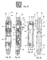
- FIGS. 20 to 29 show a mode of production of a multiple locking fitting 70 bolts according to the invention in which the rod of maneuver 71 is adapted to be introduced inside of chamber 5 and extends parallel to the walls side 64, 65 of chamber 5.
- the bolt holder auxiliary 72 has the general shape of an elongated rod flat parallel to the rod 71 and projecting door on one of its main faces a block 73 of material to the interior of which is formed the opening 74 of said auxiliary latch holder 72.
- the opening 74 of the auxiliary bolt holder 72 leads to a notch 75 of at least one, which acts as the front wall 76 of the auxiliary box 77, front or rear walls 76, 78 of body 79 of said box 77.
- the auxiliary unit 77 has a plane of symmetry 80, at least for its external configuration, so that each of the two walls 76, 78 has a notch 75 adapted to receive the tail 25 of an auxiliary bolt 26.
- the body 79 of the auxiliary box 77 comprises at least two regions 81 in each of which is provided a tapped hole 82 adapted to receive a corresponding screw 83 for fixing the auxiliary box 77 to the front wall 10 of chamber 5 of profile 6.
- Each of the regions 81 has a means 84 in projection, for example a riveting element, suitable for pass through a groove 85 of the bolt holder 72 and cooperate with a corresponding hole 86 of the cover 87 for the fixing said cover 87 to the body 79 of the housing auxiliary 77 after introduction of the bolt holder 72 to the interior of the interior cavity 88 of the housing 77.
- a means 84 in projection for example a riveting element
- the auxiliary box 77 presents to each of its longitudinal ends an opening 89 for the passage of one end 90 of the auxiliary bolt holder 72 shaped so that it can be connected to a rod of operation 71.
- the opening 89 has a flattened section and is formed between the corresponding region 81 and the cover 87.
- each of the ends 90 of the auxiliary latch holder 72 has a flattened portion 91 passing through the opening 89 and having the groove 85, extended outward by at least one tab 92 provided with a hole 93 for fixing the end of a rod 71 for example by means of a screw.
- Each flattened part 91 has a length at least equal to the stroke of the bolt carrier.
- the auxiliary bolt holder 72 includes the projecting block 73 described above, as well as a ratchet of positioning similar to that of the assembly of command (see below).
- the end 90 has preferably two legs 92 between which comes insert the end of the rod 71.
- the auxiliary box 77 is practically necessarily introduced inside chamber 5 by one end of it. At time the introduction of the auxiliary box 77 into the chamber 5, the bolt holder 72 is already fixed to the rods 71 corresponding.
- box 77 If the box 77 is connected to another box auxiliary, the latter will be fixed to the rod 71 before its introduction inside the room.
- the housing 77 is equipped with Figure 24 of a spring 77a for adaptation to a chamber 5 of great width in the transverse direction 48.
- the locking fitting 70 comprises an assembly of control consisting of a main box 95 adapted to be inserted inside chamber 5 of the profile 6 by a corresponding light 14 formed in the side wall of chamber 5 and profile 6 constituting the wall and interior facade 15 of the sliding leaf 2, and a cover 96 adapted to close off an identical light 97 formed on the other wall 29 of chamber 5.
- the cover 96 has on its face interior two conformations 98 each comprising a tapped hole 99 adapted to receive a screw 100 for the fixing the main box 95 and the cover 96 to the profile 6 of the sliding leaf 2.
- the main box 95 is a cross sectional profile substantially in the form of U of which each of the side walls 101, 102 has its edge respective exterior 103, 104 folded down substantially at right angle to the other side wall 102, 101 for guide the sliding assembly 94.
- the sliding assembly 94 shown in the figures 20 and 21 is known. It includes, in particular, a operating member 105, a pawl 106 adapted to rock against the action of springs so that keep the sliding assembly 94 stably in each of its extreme positions and an organ anti-false operation 107 of which a feeler finger 107c is adapted to bear against a wall 107a of the keeper 107b to move said member 107 and authorize a sliding of the sliding assembly 94 from the position open in the locked position of figure 20.
- the known sliding assembly 94 has been modified and shaped so as to include, at its end longitudinal 108 shown in the upper part Figures 20 and 21, a light 109 for the passage of the corresponding screw 100 for fixing the housing main 94, and a tab 110 pierced with a hole 111 for connect this tab 110 to a rod 71 by a means of fixing, for example by a screw or a rivet 112.
- the screw 112 can be put in place through the light 97 while the main box 95 is only partially introduced into light 14 corresponding.
- the sliding assembly 94 has at its other longitudinal end 113 of the stop means 114 adapted to receive, when the main box 95 is completely introduced into the light 14 corresponding, complementary stop means 115 formed at the end 116 of a second rod 71 for allow the sliding assembly 94 to drive said second rod 71 in its sliding movements in both directions, and means to block them complementary stop means 115 in their position in engagement with the stop means 114 of the assembly sliding 94.
- the means for blocking the complementary stop means 115 in their position in engagement with the stop means 114 of the end 113 are movable means relative to the sliding assembly 94 and adapted to be actuated from outside bedroom 5 through the light 97 can be closed off by the cover 95.
- the sliding assembly 94 has a removable plate 118 shaped so to allow the movement of the assembly to be controlled sliding 94 from the outside of the opening 2 by means a key 119 actuating a lock cylinder 120 at the end of which is fixed a disc 122 carrying a eccentric finger 123 extending axially.
- the plate 118 has two transverse walls 124, 125 between which the finger 123 can penetrate when the disc 122 rotates in a either way to move plate 118 in the corresponding longitudinal direction.
- the walls 124 and 125 extend over a part only the width of the plate 118 to release the bottom 126 of said plate 118 to allow free displacement of finger 123 during rotation of the disc 122 before and after moving the plate 118.
- the end 116 of the rod 71 has two tabs 127 adapted to extend and slide from on either side of the corresponding fixing screw 100 of the main housing 95.
- Each tab 127 comprises at its free end an element 128 projecting towards the outside adapted to engage with a notch complementary 129 of a side wing 130 corresponding to the sliding assembly 94.
- the plate removable 118 blocks each tab 127 in its engaged position in which the protruding member 128 is engaged in the corresponding notch 129.
- the plaque removable 118 present on its bottom 126 in contact with the bottom 131 of the sliding assembly 94 an opening 132 allowing the passage of a pin 117 pivotally mounted around a finger 133 fixed to the bottom 131 of the assembly sliding.
- the opening 132 of the bottom 126 of the plate 117 with a thinned edge 134 so as to allow pivoting pin 117 around finger 132 to block said edge thinned 134 and therefore the plate 118 on the bottom 131 of the sliding assembly 94.
- the plate 118 has at besides a longitudinal projection 135 which is inserted between the two tabs 127 to immobilize the element 128 protruding into the notches 129 and therefore immobilize the tongues relative to the assembly sliding 94.
- connections between the rod 71 and the assembly sliding door 94 which we have just described are mobile links which facilitate the introduction of elements inside profile 6 by the end of the latter, in particular allowing a break angular at each link.
- connection by the screw 111, in the part upper of Figures 20 and 21, or the connection by claws 128 of the tabs 127 which are housed in the notches 129, allow easy connection, fast and flexible with the sliding assembly 94.
- auxiliary boxes and auxiliary bolt holders described above can be used with sliding assemblies and control assemblies different from those described.
Landscapes
- Mechanical Engineering (AREA)
- Engineering & Computer Science (AREA)
- Power-Operated Mechanisms For Wings (AREA)
- Connection Of Plates (AREA)
- Wing Frames And Configurations (AREA)
- Freezers Or Refrigerated Showcases (AREA)
- Closing And Opening Devices For Wings, And Checks For Wings (AREA)
- Seal Device For Vehicle (AREA)
- Lock And Its Accessories (AREA)
- Supports Or Holders For Household Use (AREA)
- Hinges (AREA)
- Time Recorders, Dirve Recorders, Access Control (AREA)
- Infusion, Injection, And Reservoir Apparatuses (AREA)
Applications Claiming Priority (2)
| Application Number | Priority Date | Filing Date | Title |
|---|---|---|---|
| FR9804849A FR2777589B1 (fr) | 1998-04-17 | 1998-04-17 | Ferrure de verrouillage a au moins deux penes de condamnation pour ouvrant coulissant de porte, fenetre ou analogue |
| FR9804849 | 1998-04-17 |
Publications (2)
| Publication Number | Publication Date |
|---|---|
| EP0950785A1 true EP0950785A1 (de) | 1999-10-20 |
| EP0950785B1 EP0950785B1 (de) | 2003-10-08 |
Family
ID=9525378
Family Applications (1)
| Application Number | Title | Priority Date | Filing Date |
|---|---|---|---|
| EP99400734A Expired - Lifetime EP0950785B1 (de) | 1998-04-17 | 1999-03-25 | Verriegelungsbeschlag mit mindestens zwei Riegeln für Schiebetür, Schiebefenster oder ähnliches |
Country Status (10)
| Country | Link |
|---|---|
| US (1) | US6585301B1 (de) |
| EP (1) | EP0950785B1 (de) |
| CN (1) | CN1239176A (de) |
| AT (1) | ATE251706T1 (de) |
| BR (1) | BR9901060A (de) |
| CA (1) | CA2267521A1 (de) |
| DE (1) | DE69911834T2 (de) |
| ES (1) | ES2207917T3 (de) |
| FR (1) | FR2777589B1 (de) |
| TW (1) | TW425454B (de) |
Cited By (6)
| Publication number | Priority date | Publication date | Assignee | Title |
|---|---|---|---|---|
| FR2817894A1 (fr) * | 2000-12-13 | 2002-06-14 | Ferco Int Usine Ferrures | Organe de commande pour ouvrant coulissant |
| GR20010100500A (el) * | 2001-10-30 | 2003-06-17 | Παναγιωτης Σπηλιοπουλος | Χωνευτη κλειδαρια ασφαλειας με συρομενο πιρο για προφιλ αλουμινιου αυξημενης αντοχης και καλαισθησιας |
| WO2007147503A1 (en) * | 2006-06-20 | 2007-12-27 | Master S.R.L. | Closing system for door and window casings and casing comprising this closing system |
| FR2907484A1 (fr) * | 2006-10-23 | 2008-04-25 | Croisee D S Sa | Dispositif de blocage en position fermee d'un vantail coulissant dans un dormant |
| FR2907483A1 (fr) * | 2006-10-23 | 2008-04-25 | Croisee D S Sa | Dispositif de blocage en position fermee d'un vantail coulissant dans un dormant |
| FR3027937A1 (fr) * | 2014-10-30 | 2016-05-06 | Profils Systemes | Dispositif de fermeture pour menuiserie coulissante et menuiserie adaptee |
Families Citing this family (11)
| Publication number | Priority date | Publication date | Assignee | Title |
|---|---|---|---|---|
| US8490972B1 (en) | 2002-08-23 | 2013-07-23 | Shfl Entertainment, Inc. | Automatic card shuffler |
| US7461843B1 (en) * | 2002-08-23 | 2008-12-09 | Elixir Gaming Technologies, Inc. | Automatic card shuffler |
| US7644923B1 (en) * | 2002-08-23 | 2010-01-12 | Shuffle Master, Inc. | Automatic card shuffler with dynamic de-doubler |
| FR2865231B1 (fr) * | 2004-01-15 | 2006-03-24 | Ferco Int Usine Ferrures | Ferrure de verrouillage pour ouvrant coulissant |
| CN101889124B (zh) * | 2008-09-29 | 2014-02-12 | 奥斯特拉尔锁具私人责任有限公司 | 滑动门和窗户锁 |
| CN102606011B (zh) * | 2012-04-16 | 2014-11-26 | 希美克(广州)实业有限公司 | 具有防撬功能的推拉门窗锁 |
| CN109577769A (zh) * | 2017-09-28 | 2019-04-05 | 天津木艺家节能建材科技股份有限公司 | 一种新型纱窗锁 |
| DE102018111201A1 (de) * | 2018-05-09 | 2019-11-14 | Roto Frank Ag | Beschlaganordnung für ein Schiebefenster oder eine Schiebetür |
| US11142927B2 (en) | 2019-01-10 | 2021-10-12 | Katerra Inc. | Door locking apparatus |
| CN113585516B (zh) * | 2021-06-21 | 2026-01-06 | 青岛滨海建设集团有限公司 | 一种装配式建筑墙体对接机构 |
| CN114016816B (zh) * | 2021-10-29 | 2022-12-13 | 科都电气股份有限公司 | 一种锁定配合部件和使用其的手自一体化锁定机构及使用该机构的设备 |
Citations (4)
| Publication number | Priority date | Publication date | Assignee | Title |
|---|---|---|---|---|
| US5290077A (en) * | 1992-01-14 | 1994-03-01 | W&F Manufacturing, Inc. | Multipoint door lock assembly |
| EP0629760A1 (de) * | 1993-06-16 | 1994-12-21 | Rémy Fraigneau | Schloss für Fenster- oder ähnlichen Schliebeflügeln |
| EP0757146A1 (de) * | 1995-07-31 | 1997-02-05 | Stremler | Verriegelungsvorrichtung mit mindestens einem Riegel für einen Gleitrahmen |
| EP0801194A1 (de) * | 1996-04-11 | 1997-10-15 | Giesse Group Iberia, S.A. | Mehrpunkt-Verriegelungsstruktur für einen Verschlussmechanismus mit Gleitschiene |
Family Cites Families (4)
| Publication number | Priority date | Publication date | Assignee | Title |
|---|---|---|---|---|
| US2924475A (en) * | 1957-03-26 | 1960-02-09 | Fred J Russell | Sliding door latch with dead lock |
| US3074749A (en) * | 1959-11-09 | 1963-01-22 | Yale & Towne Mfg Co | Sliding door lock |
| FR2603931B1 (fr) * | 1986-09-16 | 1994-01-21 | Ferco Internal Usine Ferrures Ba | Ferrure de verrouillage notamment pour ouvrant coulissant |
| FR2701056B1 (fr) * | 1993-02-01 | 1995-04-07 | Stremler | Dispositif de réglage de crochet de verrouillage, notamment pour châssis coulissant. |
-
1998
- 1998-04-17 FR FR9804849A patent/FR2777589B1/fr not_active Expired - Fee Related
-
1999
- 1999-03-25 DE DE69911834T patent/DE69911834T2/de not_active Expired - Fee Related
- 1999-03-25 AT AT99400734T patent/ATE251706T1/de not_active IP Right Cessation
- 1999-03-25 EP EP99400734A patent/EP0950785B1/de not_active Expired - Lifetime
- 1999-03-25 ES ES99400734T patent/ES2207917T3/es not_active Expired - Lifetime
- 1999-04-13 US US09/290,840 patent/US6585301B1/en not_active Expired - Fee Related
- 1999-04-14 CA CA002267521A patent/CA2267521A1/en not_active Abandoned
- 1999-04-16 CN CN99107649.4A patent/CN1239176A/zh active Pending
- 1999-04-16 BR BR9901060-7A patent/BR9901060A/pt active Search and Examination
- 1999-06-28 TW TW088106142A patent/TW425454B/zh not_active IP Right Cessation
Patent Citations (4)
| Publication number | Priority date | Publication date | Assignee | Title |
|---|---|---|---|---|
| US5290077A (en) * | 1992-01-14 | 1994-03-01 | W&F Manufacturing, Inc. | Multipoint door lock assembly |
| EP0629760A1 (de) * | 1993-06-16 | 1994-12-21 | Rémy Fraigneau | Schloss für Fenster- oder ähnlichen Schliebeflügeln |
| EP0757146A1 (de) * | 1995-07-31 | 1997-02-05 | Stremler | Verriegelungsvorrichtung mit mindestens einem Riegel für einen Gleitrahmen |
| EP0801194A1 (de) * | 1996-04-11 | 1997-10-15 | Giesse Group Iberia, S.A. | Mehrpunkt-Verriegelungsstruktur für einen Verschlussmechanismus mit Gleitschiene |
Cited By (7)
| Publication number | Priority date | Publication date | Assignee | Title |
|---|---|---|---|---|
| FR2817894A1 (fr) * | 2000-12-13 | 2002-06-14 | Ferco Int Usine Ferrures | Organe de commande pour ouvrant coulissant |
| EP1217152A1 (de) * | 2000-12-13 | 2002-06-26 | Ferco International Ferrures et Serrures de Bâtiment | Betätigungsvorrichtung für einen Schiebeflügel |
| GR20010100500A (el) * | 2001-10-30 | 2003-06-17 | Παναγιωτης Σπηλιοπουλος | Χωνευτη κλειδαρια ασφαλειας με συρομενο πιρο για προφιλ αλουμινιου αυξημενης αντοχης και καλαισθησιας |
| WO2007147503A1 (en) * | 2006-06-20 | 2007-12-27 | Master S.R.L. | Closing system for door and window casings and casing comprising this closing system |
| FR2907484A1 (fr) * | 2006-10-23 | 2008-04-25 | Croisee D S Sa | Dispositif de blocage en position fermee d'un vantail coulissant dans un dormant |
| FR2907483A1 (fr) * | 2006-10-23 | 2008-04-25 | Croisee D S Sa | Dispositif de blocage en position fermee d'un vantail coulissant dans un dormant |
| FR3027937A1 (fr) * | 2014-10-30 | 2016-05-06 | Profils Systemes | Dispositif de fermeture pour menuiserie coulissante et menuiserie adaptee |
Also Published As
| Publication number | Publication date |
|---|---|
| CA2267521A1 (en) | 1999-10-17 |
| DE69911834D1 (de) | 2003-11-13 |
| BR9901060A (pt) | 2000-01-18 |
| ATE251706T1 (de) | 2003-10-15 |
| US6585301B1 (en) | 2003-07-01 |
| EP0950785B1 (de) | 2003-10-08 |
| ES2207917T3 (es) | 2004-06-01 |
| TW425454B (en) | 2001-03-11 |
| FR2777589A1 (fr) | 1999-10-22 |
| DE69911834T2 (de) | 2004-08-12 |
| CN1239176A (zh) | 1999-12-22 |
| FR2777589B1 (fr) | 2000-05-26 |
Similar Documents
| Publication | Publication Date | Title |
|---|---|---|
| EP0950785B1 (de) | Verriegelungsbeschlag mit mindestens zwei Riegeln für Schiebetür, Schiebefenster oder ähnliches | |
| EP0869240B1 (de) | Schlossbeschlag für Schiebetür, Schiebefenster oder ähnliches | |
| FR2777588A1 (fr) | Dispositif de verrouillage pour ouvrant coulissant | |
| BE1020832A3 (fr) | Dispositif de commande de verrouillage pour vantail. | |
| EP0801194A1 (de) | Mehrpunkt-Verriegelungsstruktur für einen Verschlussmechanismus mit Gleitschiene | |
| CH633605A5 (fr) | Dispositif de serrure pour porte. | |
| EP1030015B1 (de) | Verriegelungsbeschlag des Typs mit Treibstangen oder ähnlichem | |
| EP0881347A1 (de) | Verriegelungsvorrichtung für eine Schiebetür oder ein Schiebefenster, oder ähnlichem | |
| EP0220127A1 (de) | Verriegelungseinrichtung für Schiebeflügel | |
| EP0060208A1 (de) | Treibstangengetriebe insbesondere Treibstangenschloss, für Tür, Fenster od. dgl. | |
| FR2795761A1 (fr) | Ensemble d'accrochage en position ouverte d'un vantail | |
| EP0866204B1 (de) | Einbruchsichere Verriegelungsvorrichtung für einen Rolladenschrank | |
| EP1908901B1 (de) | Griff zum Öffnen und Schließen von Öffnungsflügeln | |
| FR2863000A1 (fr) | Serrure de porte a empennage automatique | |
| EP1431479B1 (de) | Beschlag für Schiebetür, Schiebefenster oder ähnliches | |
| FR2702511A1 (fr) | Dispositif de serrure pour menuiserie à vantaux coulissants. | |
| EP1132558B1 (de) | Treibstangenschloss für eine Stalltür | |
| EP3684996B1 (de) | Verschlussanordnung für eine doppeltür | |
| FR2978189A1 (fr) | Serrure automatique, pene rotatif | |
| EP0359668A1 (de) | Sicherheitsvorrichtung für Flügel | |
| FR2846695A1 (fr) | Ensemble de blocage au sol d'au moins un vantail de portail notamment | |
| FR2807464A1 (fr) | Cremone ou cremone-serrure pour porte fermiere | |
| FR3159405A1 (fr) | Dispositif anti-enfoncement | |
| FR2978188A1 (fr) | Serrure automatique, pene circulaire | |
| EP2253787B1 (de) | Schließvorrichtung mit Basküleverschluss |
Legal Events
| Date | Code | Title | Description |
|---|---|---|---|
| PUAI | Public reference made under article 153(3) epc to a published international application that has entered the european phase |
Free format text: ORIGINAL CODE: 0009012 |
|
| AK | Designated contracting states |
Kind code of ref document: A1 Designated state(s): AT DE ES GB GR IT |
|
| AX | Request for extension of the european patent |
Free format text: AL;LT;LV;MK;RO;SI |
|
| 17P | Request for examination filed |
Effective date: 19990929 |
|
| AKX | Designation fees paid |
Free format text: AT DE ES GB GR IT |
|
| GRAH | Despatch of communication of intention to grant a patent |
Free format text: ORIGINAL CODE: EPIDOS IGRA |
|
| GRAS | Grant fee paid |
Free format text: ORIGINAL CODE: EPIDOSNIGR3 |
|
| GRAA | (expected) grant |
Free format text: ORIGINAL CODE: 0009210 |
|
| AK | Designated contracting states |
Kind code of ref document: B1 Designated state(s): AT DE ES GB GR IT |
|
| PG25 | Lapsed in a contracting state [announced via postgrant information from national office to epo] |
Ref country code: AT Free format text: LAPSE BECAUSE OF FAILURE TO SUBMIT A TRANSLATION OF THE DESCRIPTION OR TO PAY THE FEE WITHIN THE PRESCRIBED TIME-LIMIT Effective date: 20031008 |
|
| REG | Reference to a national code |
Ref country code: GB Ref legal event code: FG4D Free format text: NOT ENGLISH |
|
| GBT | Gb: translation of ep patent filed (gb section 77(6)(a)/1977) |
Effective date: 20031008 |
|
| REF | Corresponds to: |
Ref document number: 69911834 Country of ref document: DE Date of ref document: 20031113 Kind code of ref document: P |
|
| REG | Reference to a national code |
Ref country code: GR Ref legal event code: EP Ref document number: 20030405075 Country of ref document: GR |
|
| PGFP | Annual fee paid to national office [announced via postgrant information from national office to epo] |
Ref country code: GR Payment date: 20040330 Year of fee payment: 6 |
|
| REG | Reference to a national code |
Ref country code: ES Ref legal event code: FG2A Ref document number: 2207917 Country of ref document: ES Kind code of ref document: T3 |
|
| PLBE | No opposition filed within time limit |
Free format text: ORIGINAL CODE: 0009261 |
|
| STAA | Information on the status of an ep patent application or granted ep patent |
Free format text: STATUS: NO OPPOSITION FILED WITHIN TIME LIMIT |
|
| 26N | No opposition filed |
Effective date: 20040709 |
|
| PG25 | Lapsed in a contracting state [announced via postgrant information from national office to epo] |
Ref country code: GR Free format text: LAPSE BECAUSE OF NON-PAYMENT OF DUE FEES Effective date: 20051004 |
|
| GBPC | Gb: european patent ceased through non-payment of renewal fee |
Effective date: 20070325 |
|
| PG25 | Lapsed in a contracting state [announced via postgrant information from national office to epo] |
Ref country code: GB Free format text: LAPSE BECAUSE OF NON-PAYMENT OF DUE FEES Effective date: 20070325 |
|
| PGFP | Annual fee paid to national office [announced via postgrant information from national office to epo] |
Ref country code: GB Payment date: 20060322 Year of fee payment: 8 |
|
| PGFP | Annual fee paid to national office [announced via postgrant information from national office to epo] |
Ref country code: DE Payment date: 20090320 Year of fee payment: 11 |
|
| PG25 | Lapsed in a contracting state [announced via postgrant information from national office to epo] |
Ref country code: DE Free format text: LAPSE BECAUSE OF NON-PAYMENT OF DUE FEES Effective date: 20101001 |
|
| PGFP | Annual fee paid to national office [announced via postgrant information from national office to epo] |
Ref country code: ES Payment date: 20120327 Year of fee payment: 14 |
|
| PGFP | Annual fee paid to national office [announced via postgrant information from national office to epo] |
Ref country code: IT Payment date: 20140325 Year of fee payment: 16 |
|
| REG | Reference to a national code |
Ref country code: ES Ref legal event code: FD2A Effective date: 20150710 |
|
| PG25 | Lapsed in a contracting state [announced via postgrant information from national office to epo] |
Ref country code: ES Free format text: LAPSE BECAUSE OF NON-PAYMENT OF DUE FEES Effective date: 20130326 |
|
| PG25 | Lapsed in a contracting state [announced via postgrant information from national office to epo] |
Ref country code: IT Free format text: LAPSE BECAUSE OF NON-PAYMENT OF DUE FEES Effective date: 20150325 |