EP1217152A1 - Betätigungsvorrichtung für einen Schiebeflügel - Google Patents
Betätigungsvorrichtung für einen Schiebeflügel Download PDFInfo
- Publication number
- EP1217152A1 EP1217152A1 EP01402701A EP01402701A EP1217152A1 EP 1217152 A1 EP1217152 A1 EP 1217152A1 EP 01402701 A EP01402701 A EP 01402701A EP 01402701 A EP01402701 A EP 01402701A EP 1217152 A1 EP1217152 A1 EP 1217152A1
- Authority
- EP
- European Patent Office
- Prior art keywords
- slide
- housing
- control member
- member according
- light
- Prior art date
- Legal status (The legal status is an assumption and is not a legal conclusion. Google has not performed a legal analysis and makes no representation as to the accuracy of the status listed.)
- Granted
Links
- 238000003780 insertion Methods 0.000 claims abstract description 4
- 230000037431 insertion Effects 0.000 claims abstract description 4
- 238000005452 bending Methods 0.000 claims description 2
- 230000000694 effects Effects 0.000 claims description 2
- 230000005489 elastic deformation Effects 0.000 description 1
- 230000012010 growth Effects 0.000 description 1
- 238000004519 manufacturing process Methods 0.000 description 1
- 229910001092 metal group alloy Inorganic materials 0.000 description 1
- 238000000034 method Methods 0.000 description 1
- 238000000465 moulding Methods 0.000 description 1
- 210000000056 organ Anatomy 0.000 description 1
- 230000000284 resting effect Effects 0.000 description 1
- 229920002994 synthetic fiber Polymers 0.000 description 1
Images


Classifications
-
- E—FIXED CONSTRUCTIONS
- E05—LOCKS; KEYS; WINDOW OR DOOR FITTINGS; SAFES
- E05B—LOCKS; ACCESSORIES THEREFOR; HANDCUFFS
- E05B65/00—Locks or fastenings for special use
- E05B65/08—Locks or fastenings for special use for sliding wings
- E05B65/087—Locks or fastenings for special use for sliding wings the bolts sliding parallel to the wings
-
- E—FIXED CONSTRUCTIONS
- E05—LOCKS; KEYS; WINDOW OR DOOR FITTINGS; SAFES
- E05B—LOCKS; ACCESSORIES THEREFOR; HANDCUFFS
- E05B41/00—Locks with visible indication as to whether the lock is locked or unlocked
Definitions
- the present invention relates to an opening control member sliding for windows, doors, patio doors and the like.
- control members for sliding doors comprising a housing intended to be mounted in a recess made in a sliding sash post.
- This case contains a slide movable along the axis of the housing by accessible control means by the user.
- This slide has a protrusion protruding into a light made in the bottom of the housing, this protrusion comprising connecting means allowing it to control the translation of rods mounted on the sash upright between a locking position and unlocking the sash.
- the object of the present invention is to simplify the production of a above type control, reducing the number of parts and making it easier mounting and assembling this control member, while offering more flexibility in design with regard to the visible part of the organ.
- this control member is characterized in that said housing is open at at least one of its axial ends, the light practiced in the bottom of the housing opening outwards at said level open axial end of the housing to allow the introduction of said slide in the housing by said end and the insertion of the protruding protrusion of this slide in said open light, the end of the slide opposite to said open axial end of the housing carrying a tab bearing elastically on the bottom of said housing, said bottom having a boss elongated in the axial direction of the housing whose ends cooperate with the end of the tongue to define two separate axial positions of said slide inside the case.
- control member according to the invention essentially consists of two pieces, namely a housing and a slide, the latter being easy to mount in the housing since it is sufficient to engage it by one of the ends open the case.
- the face visible exterior of the case may have an improved design and / or a cover to hide the fasteners.
- the side walls of the housing which border said open axial end of the housing can flex elastically, perpendicular to the axis of said light, said protrusion projecting from the slide comprising on each of its lateral faces a projection directed perpendicular to the axis of the slide, said light having in the plane of the open end of the housing, a narrowed entry of width less than the distance between the opposite ends of the two outgrowths, these being capable of causing elastic bending towards the outside of said side walls of the housing during the axial introduction of the slide inside the case.
- the elastic deformation of the side walls of the housing thus allows not only to introduce the slide in the case, but also to house definitively in translation said slide in the housing.
- said light from the bottom of the housing comprises opposite said narrowed entry of said light, a weaker light width allowing the passage of said protuberance of the slide, the lateral recesses which connect said lights constituting stops for said growths to limit the sliding stroke of the slide.
- the lateral recesses which connect said narrowed inlet to said light and the lateral recesses which connect said light with said narrower width constitute stops for said protrusions to limit the slide stroke between the locked position and the unlocked position.
- control member for opening sliding comprises a housing 1 intended to be mounted in a recess 2 (see figure 10) made in an upright 3 of the sliding sash.
- the housing 1 contains a slide 4 movable along the axis XX 'of said housing 1 by control means accessible by the user.
- the slide 4 has a protrusion 5 in the form of a projecting fork (see in particular FIG. 9) in a light 6 made in the bottom 7 of the housing 1.
- the protrusion 5 comprises connecting means allowing it to order the translation of rods, not shown, mounted on the upright 3, between a locking and unlocking position of the opening.
- the housing 1 is open to at least one 1a of its axial ends 1a, 1b.
- the light 6 formed in the bottom 7 of the housing 1 opens out to the exterior (see in particular Figures 1, 2 and 9) at the axial end open 1a of the housing 1 to allow the introduction of the slide 4 in the housing 1 by said end 1a and the insertion of the protrusion 5 projecting from this slide in said open light 6.
- the end of the slide 4 opposite said open axial end of the housing 1 carries a tongue 8 resting elastically on the bottom 7 of said housing 1.
- the bottom 7 of the housing 1 has a boss 9 elongated in the axial direction X-X 'of the housing 1.
- the ends 9a, 9b of the boss 9 cooperate with the end 8a of the tongue 8 to define two separate axial positions of the slide 4 to the interior of the housing 1, as will be explained in detail below.
- This boss also allows sliding without play and effort of the slide to inside the case.
- the side walls 10 of the housing 1 which border the open axial end 1a of the case 1 can flex elastically, perpendicular to the axis XX 'of said light 6.
- protruding protrusion 5 of the slide 4 has (see Figures 7, 9) on each of its lateral faces a protrusion 11 directed perpendicular to the axis XX 'of the slide 4.
- the light 6 present in the plane of the open end 1a of the box 1, a narrowed entry 6a of width less than the distance included between the opposite ends of the two protuberances 11.
- the latter are capable of causing elastic flexion towards the outside of the side walls 10 of the housing 1 during the axial introduction of the slide 4 to inside the housing 1.
- the protuberances 11 have a chamfered end 11a to facilitate their passage through the narrowed entry 6a of the light 6.
- the light 6 of the bottom 7 of the housing 1 comprises opposite the entrance narrowed 6a of this light 6, a light 12 of smaller width allowing the passage of the protuberance 5 of the slide 4.
- the lateral recesses 12a which connect the light 6 to the light 12 constitute stops for the protuberances 11 in order to limit the travel of the sliding of the slide 4 towards the end 1b of the housing 1.
- the lateral recesses 6b which connect the narrowed entry 6a to the light 6 and the lateral recesses 12a which connect the light 6 with the light narrowed 12 constitute stops for the protuberances 11 to limit the stroke of the slide 4 between the locked position and the unlocked position, as shown in particular in FIG. 9A.
- the locked and unlocked above correspond to the two opposite ends 9a, 9b of the elongated boss 9 which cooperate with the elastic tongue 8 of the slide 4.
- the slide 4 is made of single piece, including the protrusion 5 and the tongue 8. It is of section general rectangular adapted to that of the housing 1.
- the protrusion 5 of the slide 4 is shaped like a fork allowing the attachment of the stud 13 (see Figure 10) of a rod or a means of rod control.
- the housing 1 carries on its face longitudinal opposite its bottom 7, a plate 14 having at its ends opposite holes 15 for fixing screws to the upright 3 of the opening. These holes 15 are located beyond the ends 1a, 1b of the housing 1 in which is accommodated the slide 4.
- the plate 14 has a elongated opening 16 of length less than the length of the slide 4 plus the stroke of it.
- the slide 4 has on its face opposite the elongated opening 16 of the plate 14 an oblong bowl 17 serving as an accessible gripping means to the user's fingers to move the slide 4, between the positions of locking and unlocking.
- the slide 4 has on its opposite face of the plate 14 of the flat zones 18, 19 located on the side and on the other side of the bowl 17.
- the visible zone 18 or 19 of the slide 4 preferably has an indication 18a, 19a for example a green or red color showing the user one or the other position above.
- the end of the slide 4 adjacent to the tongue 8 has a shoulder 20a adapted to snap onto the edge of the light 16 of the plate 14, under the effect of the elastic return of the tongue 8 when the slide 4 is in the locked position.
- This shoulder 20a thus constitutes an anti-intrusion means.
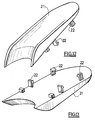
- the plate 14 may have a design visible from the outside, as shown for example by the flanges 14a visible in FIG. 4. Furthermore, the plate 14 has (see FIG. 1 to 3) on its end parts projecting beyond ends 1a, 1b of the housing 1 of the orifices 20 able to receive by snap-fastening the fixing lugs 22 of a frame 21 shown in FIGS. 12 and 13 adapted to cover the holes 15 of the fixing screws or the whole of the plate 14
- This cover 21 may be in two parts or in one piece. In the latter case, the frame has a light allowing access to the bowl 17 of the slide. In all cases, the cover (s) have a variable design.
- the housing 1 and the slide 4 can be produced by molding synthetic materials or metal alloys.
- the end of the slide 4 comprising the tongue 8 is introduced into the end 1a of the housing 1.
- the operator pushes on the bowl 17 of the slide, to flex the elastic tongue 8 so that the upper edge front of the slide passes under the front edge of the opening 16 of the plate 14. Simultaneously, the end 8a of the tongue 8 crosses the stepped end 9a of the boss 9 formed at the end of the bottom 7 of the housing.
- This position corresponds to the locked position.
- the slide 4 slides substantially clearance and friction, inside the case.
- the above play of the slide in the case can be annihilated by fixed or elastic means and preferably by bosses made on the rear face of the bottom wall of the slide and / or the internal face of the back wall of the case.
Landscapes
- Formation And Processing Of Food Products (AREA)
- Power-Operated Mechanisms For Wings (AREA)
- Adjustable Resistors (AREA)
- Lock And Its Accessories (AREA)
- Glass Compositions (AREA)
- Beans For Foods Or Fodder (AREA)
- Wing Frames And Configurations (AREA)
Applications Claiming Priority (2)
| Application Number | Priority Date | Filing Date | Title |
|---|---|---|---|
| FR0016251A FR2817894B1 (fr) | 2000-12-13 | 2000-12-13 | Organe de commande pour ouvrant coulissant |
| FR0016251 | 2000-12-13 |
Publications (2)
| Publication Number | Publication Date |
|---|---|
| EP1217152A1 true EP1217152A1 (de) | 2002-06-26 |
| EP1217152B1 EP1217152B1 (de) | 2004-05-26 |
Family
ID=8857610
Family Applications (1)
| Application Number | Title | Priority Date | Filing Date |
|---|---|---|---|
| EP01402701A Expired - Lifetime EP1217152B1 (de) | 2000-12-13 | 2001-10-18 | Betätigungsvorrichtung für einen Schiebeflügel |
Country Status (4)
| Country | Link |
|---|---|
| EP (1) | EP1217152B1 (de) |
| AT (1) | ATE267938T1 (de) |
| DE (1) | DE60103486T2 (de) |
| FR (1) | FR2817894B1 (de) |
Families Citing this family (2)
| Publication number | Priority date | Publication date | Assignee | Title |
|---|---|---|---|---|
| ITRA20050007A1 (it) * | 2005-03-14 | 2006-09-15 | Erreti Srl | Maniglia a vaschetta |
| ITRA20050009A1 (it) * | 2005-03-14 | 2006-09-15 | Erreti Srl | Maniglia a vaschetta |
Citations (4)
| Publication number | Priority date | Publication date | Assignee | Title |
|---|---|---|---|---|
| US5442881A (en) * | 1994-05-16 | 1995-08-22 | Fisher-Price, Inc. | Pressure-fit gate assembly |
| EP0859107A1 (de) * | 1997-02-18 | 1998-08-19 | Aluminio Tecnologia Y Producto S.A. | Schliessvorrichtung für verschiebbare Objekte |
| EP0950785A1 (de) * | 1998-04-17 | 1999-10-20 | Ferco International Ferrures et Serrures de Bâtiment | Verriegelungsbeschlag mit mindestens zwei Riegeln für Schiebetür, Schiebefenster oder ähnliches |
| US6050617A (en) * | 1997-04-03 | 2000-04-18 | Ferco International Ferrures Et Serrures De Batiment | Lock for sliding door, window or like closure |
-
2000
- 2000-12-13 FR FR0016251A patent/FR2817894B1/fr not_active Expired - Fee Related
-
2001
- 2001-10-18 AT AT01402701T patent/ATE267938T1/de not_active IP Right Cessation
- 2001-10-18 EP EP01402701A patent/EP1217152B1/de not_active Expired - Lifetime
- 2001-10-18 DE DE60103486T patent/DE60103486T2/de not_active Expired - Fee Related
Patent Citations (4)
| Publication number | Priority date | Publication date | Assignee | Title |
|---|---|---|---|---|
| US5442881A (en) * | 1994-05-16 | 1995-08-22 | Fisher-Price, Inc. | Pressure-fit gate assembly |
| EP0859107A1 (de) * | 1997-02-18 | 1998-08-19 | Aluminio Tecnologia Y Producto S.A. | Schliessvorrichtung für verschiebbare Objekte |
| US6050617A (en) * | 1997-04-03 | 2000-04-18 | Ferco International Ferrures Et Serrures De Batiment | Lock for sliding door, window or like closure |
| EP0950785A1 (de) * | 1998-04-17 | 1999-10-20 | Ferco International Ferrures et Serrures de Bâtiment | Verriegelungsbeschlag mit mindestens zwei Riegeln für Schiebetür, Schiebefenster oder ähnliches |
Also Published As
| Publication number | Publication date |
|---|---|
| FR2817894B1 (fr) | 2003-08-08 |
| EP1217152B1 (de) | 2004-05-26 |
| DE60103486D1 (de) | 2004-07-01 |
| ATE267938T1 (de) | 2004-06-15 |
| FR2817894A1 (fr) | 2002-06-14 |
| DE60103486T2 (de) | 2005-06-02 |
Similar Documents
| Publication | Publication Date | Title |
|---|---|---|
| EP0869241B1 (de) | Schiebetürverschluss | |
| EP0943768B1 (de) | Rückstellvorrichtung des Betätigungsorgans für ein Schlossgehäuse, Treibstangenschloss oder dergleichen | |
| CA2593966A1 (fr) | Dispositif de verrouillage et de deverrouillage a l'aide d'une cle d'un tampon ou couvercle sur un cadre, notamment de regard de chaussee | |
| EP1217152B1 (de) | Betätigungsvorrichtung für einen Schiebeflügel | |
| FR2961245A1 (fr) | Dispositif de guidage pour porte coulissante escamotable comprenant un rail demontable | |
| EP0881347B1 (de) | Verriegelungsvorrichtung für eine Schiebetür oder ein Schiebefenster, oder ähnlichem | |
| FR2686118A1 (fr) | Mecanisme de serrure pour porte ou abattant. | |
| EP0869242B1 (de) | Verriegelungsbeschlag für Schiebeflügel | |
| FR2565177A1 (fr) | Support pour autoradios, lecteurs de cassettes et autres | |
| EP0928869B1 (de) | Verriegelungsbeschlag für Tür, Fenstertür oder dergleichen | |
| FR2609314A1 (fr) | Dispositif d'assemblage rapide pour l'accrochage amovible d'un objet sur un support | |
| EP1088957B1 (de) | Treibstangenverschluss für Rahmen von Türen oder Fenstern | |
| FR3010116A1 (fr) | Gache destinee a cooperer avec la serrure d'un ouvrant de vehicule automobile | |
| FR2545139A1 (fr) | Dispositif de securite a action automatique contre les fausses manoeuvres d'une tige de verrouillage equipant un battant de fenetre ou autre | |
| FR3124536A1 (fr) | Dispositif de commande d’un système de verrouillage/déverrouillage d’un ouvrant, et menuiserie le comportant | |
| FR2892139A1 (fr) | Coquille de manoeuvre pour serrure de chassis coulissant, chassis coulissant et serrure correspondants. | |
| FR2583452A1 (fr) | Boitier de cremone a plaquer avec condamnation. | |
| FR2835868A3 (fr) | Portiere de fermeture pour un compartiment porte-objets, ou similaire, en particulier pour des vehicules automobiles | |
| FR2820163A1 (fr) | Dispositif d'assemblage et meuble meublant muni d'un tel dispositif d'assemblage | |
| EP2061944B1 (de) | Scharnierbaugruppe zur koplanaren fixierung | |
| EP1160401B1 (de) | Sichtbares Schloss für einen Flügel | |
| EP0013228B1 (de) | Vorrichtung zum Feststellen eines Fensters in einer Offenstellung | |
| FR2708307A1 (fr) | Ensemble pour la réalisation d'un châssis de survitrage. | |
| FR2514811A1 (fr) | Arret de volet | |
| FR2933118A1 (fr) | Serrure additionnelle de porte |
Legal Events
| Date | Code | Title | Description |
|---|---|---|---|
| PUAI | Public reference made under article 153(3) epc to a published international application that has entered the european phase |
Free format text: ORIGINAL CODE: 0009012 |
|
| AK | Designated contracting states |
Kind code of ref document: A1 Designated state(s): AT BE CH CY DE DK ES FI FR GB GR IE IT LI LU MC NL PT SE TR |
|
| AX | Request for extension of the european patent |
Free format text: AL;LT;LV;MK;RO;SI |
|
| 17P | Request for examination filed |
Effective date: 20020607 |
|
| AKX | Designation fees paid |
Designated state(s): AT BE CH CY DE DK ES FI FR GB GR IE IT LI LU MC NL PT SE TR |
|
| 17Q | First examination report despatched |
Effective date: 20030711 |
|
| GRAP | Despatch of communication of intention to grant a patent |
Free format text: ORIGINAL CODE: EPIDOSNIGR1 |
|
| GRAS | Grant fee paid |
Free format text: ORIGINAL CODE: EPIDOSNIGR3 |
|
| GRAA | (expected) grant |
Free format text: ORIGINAL CODE: 0009210 |
|
| AK | Designated contracting states |
Kind code of ref document: B1 Designated state(s): AT BE CH CY DE DK ES FI FR GB GR IE IT LI LU MC NL PT SE TR |
|
| PG25 | Lapsed in a contracting state [announced via postgrant information from national office to epo] |
Ref country code: FI Free format text: LAPSE BECAUSE OF FAILURE TO SUBMIT A TRANSLATION OF THE DESCRIPTION OR TO PAY THE FEE WITHIN THE PRESCRIBED TIME-LIMIT Effective date: 20040526 Ref country code: NL Free format text: LAPSE BECAUSE OF FAILURE TO SUBMIT A TRANSLATION OF THE DESCRIPTION OR TO PAY THE FEE WITHIN THE PRESCRIBED TIME-LIMIT Effective date: 20040526 Ref country code: IE Free format text: LAPSE BECAUSE OF FAILURE TO SUBMIT A TRANSLATION OF THE DESCRIPTION OR TO PAY THE FEE WITHIN THE PRESCRIBED TIME-LIMIT Effective date: 20040526 Ref country code: TR Free format text: LAPSE BECAUSE OF FAILURE TO SUBMIT A TRANSLATION OF THE DESCRIPTION OR TO PAY THE FEE WITHIN THE PRESCRIBED TIME-LIMIT Effective date: 20040526 Ref country code: AT Free format text: LAPSE BECAUSE OF FAILURE TO SUBMIT A TRANSLATION OF THE DESCRIPTION OR TO PAY THE FEE WITHIN THE PRESCRIBED TIME-LIMIT Effective date: 20040526 Ref country code: CY Free format text: LAPSE BECAUSE OF FAILURE TO SUBMIT A TRANSLATION OF THE DESCRIPTION OR TO PAY THE FEE WITHIN THE PRESCRIBED TIME-LIMIT Effective date: 20040526 |
|
| REG | Reference to a national code |
Ref country code: GB Ref legal event code: FG4D Free format text: NOT ENGLISH |
|
| REG | Reference to a national code |
Ref country code: CH Ref legal event code: EP |
|
| REG | Reference to a national code |
Ref country code: IE Ref legal event code: FG4D Free format text: FRENCH |
|
| REF | Corresponds to: |
Ref document number: 60103486 Country of ref document: DE Date of ref document: 20040701 Kind code of ref document: P |
|
| GBT | Gb: translation of ep patent filed (gb section 77(6)(a)/1977) |
Effective date: 20040721 |
|
| PG25 | Lapsed in a contracting state [announced via postgrant information from national office to epo] |
Ref country code: GR Free format text: LAPSE BECAUSE OF FAILURE TO SUBMIT A TRANSLATION OF THE DESCRIPTION OR TO PAY THE FEE WITHIN THE PRESCRIBED TIME-LIMIT Effective date: 20040826 Ref country code: SE Free format text: LAPSE BECAUSE OF FAILURE TO SUBMIT A TRANSLATION OF THE DESCRIPTION OR TO PAY THE FEE WITHIN THE PRESCRIBED TIME-LIMIT Effective date: 20040826 Ref country code: DK Free format text: LAPSE BECAUSE OF FAILURE TO SUBMIT A TRANSLATION OF THE DESCRIPTION OR TO PAY THE FEE WITHIN THE PRESCRIBED TIME-LIMIT Effective date: 20040826 |
|
| PG25 | Lapsed in a contracting state [announced via postgrant information from national office to epo] |
Ref country code: ES Free format text: LAPSE BECAUSE OF FAILURE TO SUBMIT A TRANSLATION OF THE DESCRIPTION OR TO PAY THE FEE WITHIN THE PRESCRIBED TIME-LIMIT Effective date: 20040906 |
|
| PG25 | Lapsed in a contracting state [announced via postgrant information from national office to epo] |
Ref country code: LU Free format text: LAPSE BECAUSE OF NON-PAYMENT OF DUE FEES Effective date: 20041018 |
|
| PG25 | Lapsed in a contracting state [announced via postgrant information from national office to epo] |
Ref country code: BE Free format text: LAPSE BECAUSE OF NON-PAYMENT OF DUE FEES Effective date: 20041031 Ref country code: MC Free format text: LAPSE BECAUSE OF NON-PAYMENT OF DUE FEES Effective date: 20041031 |
|
| NLV1 | Nl: lapsed or annulled due to failure to fulfill the requirements of art. 29p and 29m of the patents act | ||
| REG | Reference to a national code |
Ref country code: IE Ref legal event code: FD4D |
|
| PLBE | No opposition filed within time limit |
Free format text: ORIGINAL CODE: 0009261 |
|
| STAA | Information on the status of an ep patent application or granted ep patent |
Free format text: STATUS: NO OPPOSITION FILED WITHIN TIME LIMIT |
|
| BERE | Be: lapsed |
Owner name: FERCO INTERNATIONAL FERRURES ET SERRURES DE BATIME Effective date: 20041031 |
|
| 26N | No opposition filed |
Effective date: 20050301 |
|
| PG25 | Lapsed in a contracting state [announced via postgrant information from national office to epo] |
Ref country code: CH Free format text: LAPSE BECAUSE OF NON-PAYMENT OF DUE FEES Effective date: 20051031 Ref country code: LI Free format text: LAPSE BECAUSE OF NON-PAYMENT OF DUE FEES Effective date: 20051031 |
|
| REG | Reference to a national code |
Ref country code: CH Ref legal event code: PL |
|
| PGFP | Annual fee paid to national office [announced via postgrant information from national office to epo] |
Ref country code: DE Payment date: 20061023 Year of fee payment: 6 Ref country code: GB Payment date: 20061023 Year of fee payment: 6 |
|
| PGFP | Annual fee paid to national office [announced via postgrant information from national office to epo] |
Ref country code: IT Payment date: 20061031 Year of fee payment: 6 |
|
| BERE | Be: lapsed |
Owner name: *FERCO INTERNATIONAL FERRURES ET SERRURES DE BATIM Effective date: 20041031 |
|
| PG25 | Lapsed in a contracting state [announced via postgrant information from national office to epo] |
Ref country code: PT Free format text: LAPSE BECAUSE OF NON-PAYMENT OF DUE FEES Effective date: 20041026 |
|
| GBPC | Gb: european patent ceased through non-payment of renewal fee |
Effective date: 20071018 |
|
| PG25 | Lapsed in a contracting state [announced via postgrant information from national office to epo] |
Ref country code: DE Free format text: LAPSE BECAUSE OF NON-PAYMENT OF DUE FEES Effective date: 20080501 |
|
| PG25 | Lapsed in a contracting state [announced via postgrant information from national office to epo] |
Ref country code: GB Free format text: LAPSE BECAUSE OF NON-PAYMENT OF DUE FEES Effective date: 20071018 |
|
| PG25 | Lapsed in a contracting state [announced via postgrant information from national office to epo] |
Ref country code: IT Free format text: LAPSE BECAUSE OF NON-PAYMENT OF DUE FEES Effective date: 20071018 |
|
| PGFP | Annual fee paid to national office [announced via postgrant information from national office to epo] |
Ref country code: FR Payment date: 20141022 Year of fee payment: 14 |
|
| REG | Reference to a national code |
Ref country code: FR Ref legal event code: ST Effective date: 20160630 |
|
| PG25 | Lapsed in a contracting state [announced via postgrant information from national office to epo] |
Ref country code: FR Free format text: LAPSE BECAUSE OF NON-PAYMENT OF DUE FEES Effective date: 20151102 |