EP0950814A2 - In der Ruhelage offengehaltenes, vorgespanntes Einlassventil - Google Patents
In der Ruhelage offengehaltenes, vorgespanntes Einlassventil Download PDFInfo
- Publication number
- EP0950814A2 EP0950814A2 EP99630031A EP99630031A EP0950814A2 EP 0950814 A2 EP0950814 A2 EP 0950814A2 EP 99630031 A EP99630031 A EP 99630031A EP 99630031 A EP99630031 A EP 99630031A EP 0950814 A2 EP0950814 A2 EP 0950814A2
- Authority
- EP
- European Patent Office
- Prior art keywords
- valve
- suction valve
- suction
- spring
- seat
- Prior art date
- Legal status (The legal status is an assumption and is not a legal conclusion. Google has not performed a legal analysis and makes no representation as to the accuracy of the status listed.)
- Withdrawn
Links
- 230000000694 effects Effects 0.000 abstract description 6
- 230000006835 compression Effects 0.000 description 12
- 238000007906 compression Methods 0.000 description 12
- 239000000314 lubricant Substances 0.000 description 12
- 239000000463 material Substances 0.000 description 5
- 150000004996 alkyl benzenes Chemical class 0.000 description 4
- 239000012530 fluid Substances 0.000 description 4
- 239000003507 refrigerant Substances 0.000 description 4
- XEEYBQQBJWHFJM-UHFFFAOYSA-N Iron Chemical compound [Fe] XEEYBQQBJWHFJM-UHFFFAOYSA-N 0.000 description 2
- 238000010276 construction Methods 0.000 description 2
- 235000014676 Phragmites communis Nutrition 0.000 description 1
- 230000002301 combined effect Effects 0.000 description 1
- 230000003111 delayed effect Effects 0.000 description 1
- 230000010339 dilation Effects 0.000 description 1
- 238000006073 displacement reaction Methods 0.000 description 1
- 229910052500 inorganic mineral Inorganic materials 0.000 description 1
- 229910052742 iron Inorganic materials 0.000 description 1
- 230000001050 lubricating effect Effects 0.000 description 1
- 238000004519 manufacturing process Methods 0.000 description 1
- 239000011707 mineral Substances 0.000 description 1
- 238000010943 off-gassing Methods 0.000 description 1
- 229920005862 polyol Polymers 0.000 description 1
- -1 polyol ester Chemical class 0.000 description 1
- 230000001737 promoting effect Effects 0.000 description 1
Images

Classifications
-
- F—MECHANICAL ENGINEERING; LIGHTING; HEATING; WEAPONS; BLASTING
- F04—POSITIVE - DISPLACEMENT MACHINES FOR LIQUIDS; PUMPS FOR LIQUIDS OR ELASTIC FLUIDS
- F04B—POSITIVE-DISPLACEMENT MACHINES FOR LIQUIDS; PUMPS
- F04B39/00—Component parts, details, or accessories, of pumps or pumping systems specially adapted for elastic fluids, not otherwise provided for in, or of interest apart from, groups F04B25/00 - F04B37/00
- F04B39/10—Adaptations or arrangements of distribution members
- F04B39/1073—Adaptations or arrangements of distribution members the members being reed valves
-
- F—MECHANICAL ENGINEERING; LIGHTING; HEATING; WEAPONS; BLASTING
- F16—ENGINEERING ELEMENTS AND UNITS; GENERAL MEASURES FOR PRODUCING AND MAINTAINING EFFECTIVE FUNCTIONING OF MACHINES OR INSTALLATIONS; THERMAL INSULATION IN GENERAL
- F16K—VALVES; TAPS; COCKS; ACTUATING-FLOATS; DEVICES FOR VENTING OR AERATING
- F16K3/00—Gate valves or sliding valves, i.e. cut-off apparatus with closing members having a sliding movement along the seat for opening and closing
-
- F—MECHANICAL ENGINEERING; LIGHTING; HEATING; WEAPONS; BLASTING
- F04—POSITIVE - DISPLACEMENT MACHINES FOR LIQUIDS; PUMPS FOR LIQUIDS OR ELASTIC FLUIDS
- F04B—POSITIVE-DISPLACEMENT MACHINES FOR LIQUIDS; PUMPS
- F04B39/00—Component parts, details, or accessories, of pumps or pumping systems specially adapted for elastic fluids, not otherwise provided for in, or of interest apart from, groups F04B25/00 - F04B37/00
- F04B39/10—Adaptations or arrangements of distribution members
- F04B39/104—Adaptations or arrangements of distribution members the members being parallel flexible strips
-
- Y—GENERAL TAGGING OF NEW TECHNOLOGICAL DEVELOPMENTS; GENERAL TAGGING OF CROSS-SECTIONAL TECHNOLOGIES SPANNING OVER SEVERAL SECTIONS OF THE IPC; TECHNICAL SUBJECTS COVERED BY FORMER USPC CROSS-REFERENCE ART COLLECTIONS [XRACs] AND DIGESTS
- Y10—TECHNICAL SUBJECTS COVERED BY FORMER USPC
- Y10T—TECHNICAL SUBJECTS COVERED BY FORMER US CLASSIFICATION
- Y10T137/00—Fluid handling
- Y10T137/4238—With cleaner, lubrication added to fluid or liquid sealing at valve interface
- Y10T137/4358—Liquid supplied at valve interface
-
- Y—GENERAL TAGGING OF NEW TECHNOLOGICAL DEVELOPMENTS; GENERAL TAGGING OF CROSS-SECTIONAL TECHNOLOGIES SPANNING OVER SEVERAL SECTIONS OF THE IPC; TECHNICAL SUBJECTS COVERED BY FORMER USPC CROSS-REFERENCE ART COLLECTIONS [XRACs] AND DIGESTS
- Y10—TECHNICAL SUBJECTS COVERED BY FORMER USPC
- Y10T—TECHNICAL SUBJECTS COVERED BY FORMER US CLASSIFICATION
- Y10T137/00—Fluid handling
- Y10T137/4238—With cleaner, lubrication added to fluid or liquid sealing at valve interface
- Y10T137/4358—Liquid supplied at valve interface
- Y10T137/4379—Feed by or with actuation
-
- Y—GENERAL TAGGING OF NEW TECHNOLOGICAL DEVELOPMENTS; GENERAL TAGGING OF CROSS-SECTIONAL TECHNOLOGIES SPANNING OVER SEVERAL SECTIONS OF THE IPC; TECHNICAL SUBJECTS COVERED BY FORMER USPC CROSS-REFERENCE ART COLLECTIONS [XRACs] AND DIGESTS
- Y10—TECHNICAL SUBJECTS COVERED BY FORMER USPC
- Y10T—TECHNICAL SUBJECTS COVERED BY FORMER US CLASSIFICATION
- Y10T137/00—Fluid handling
- Y10T137/7722—Line condition change responsive valves
- Y10T137/7837—Direct response valves [i.e., check valve type]
- Y10T137/7879—Resilient material valve
- Y10T137/7888—With valve member flexing about securement
- Y10T137/7891—Flap or reed
- Y10T137/7892—With stop
Definitions
- valves In positive displacement compressors employing suction and discharge valves there are both similarities and differences between the two types of valves. Normally the valves would be of the same general type. Each valve would be normally closed and would open due to a pressure differential across the valve in the direction of opening.
- the valve may be of a spring material and provide its own seating bias or separate springs may be employed. Since the suction valve(s) open into the compression chamber/cylinder they generally do not have valve backers in order to minimize the clearance volume and thus deflection of the valve is not physically limited.
- Discharge valves normally have some sort of valve backer so as to avoid excess movement/flexure of the discharge valve. Ignoring the effects of leakage, etc., an equal mass of gas is drawn into the compression chamber and discharged therefrom.
- the suction stroke takes place over, nominally, a half cycle whereas the combined compression and discharge stroke makes up, nominally, a half cycle.
- the suction valve opens as soon as the pressure differential across the suction valve can cause it to unseat.
- the pressure differential required to open the suction valve is on the order of 15-35% of the nominal suction pressure.
- compression stroke compression continues with the attendant reduction in volume/increase in density of the gas being compressed until the pressure of the compressed gas is sufficient to overcome the combined system pressure acting on the discharge valve together with spring bias of the valve member and/or separate springs.
- the pressure differential required to open the discharge valve is on the order of 20-40% of the nominal discharge pressure. Accordingly, the mass flow rate is much greater during the discharge stroke.
- suction valves have a much lower seating bias than discharge valves.
- the low seating bias is essential due to the fact that valve actuation is initiated by the force resulting from the pressure differential across the valve.
- opening generally occurs at pressures that are much lower than in the case of discharge valves. Therefore, only small pressure differences, and hence small opening forces, can be created for suction valves relative to potential pressure differences and opening forces for discharge valves. Even a small increase in the pressure differential across the suction valve results in a large percentage increase in the pressure differential across the valve. In contrast, an equal increase in the pressure differential across the discharge valve results in a much smaller percentage increase in the pressure differential because of the substantially higher nominal operating pressure.
- A is held constant, it is clear that a change in F is proportional to a change in P, or, more specifically, the percentage change in F is proportional to the percentage change in P. For example, assuming an operating condition where suction pressure is 20 psia and discharge pressure is 300 psia, at a typical overpressure value of 35%, the cylinder will rise to 405 psia before the discharge valve opens.
- the change in pressure differential across the suction valve would not increase very rapidly since the cylinder is initially charged due to the compressed gas from the clearance volume and is then acting as a vacuum pump until the suction valve opens.
- the inflow of gas to the cylinder is typically designed to occur during the last 95% of the combined expansion and suction stroke.
- the compression chamber pressure rises rapidly as the compression stroke is being completed and the pressure can continue to rise during the discharge stroke if the volume flow exiting the cylinder does not match the rate of reduction in the compression chamber volume.
- the outflow of gas from the cylinder occurs during the last 40% of the combined compression and discharge stroke. Any substantial change in one or more of these relationships can result in operational problems relative to the valves.
- a typical reciprocating compressor will have a valve plate with an integral suction port and suction valve seat.
- the film of oil present between the suction valve and its seat is very thin, on the order of a few molecular diameters. This is in part due to the fact that compression chamber pressure acts on and provides a seating bias for the suction valve during the combined compression and discharge stroke.
- the opening force applied to the suction valve is provided by a pressure differential across the valve that is created as the piston moves away from the valve during the suction stroke.
- the opening force needs to be large enough to overcome the resistance to opening caused by valve mass (inertia) and any spring or other biasing forces.
- the force also needs to be substantial enough to dilate and shear the oil film trapped between the valve and seat.
- Factors that influence the force necessary to dilate and shear the lubricant film include: the viscosity of the lubricant film, the thickness of the oil film, the inter-molecular attractive forces between the lubricant molecules, the quantity of refrigerant entrained in the oil film, the materials of construction of the suction valve and/or valve seat, and the rate of refrigerant outgassing.
- POE polyol ester
- HFC refrigerants such as R134a, R404A, and R507
- the relatively high viscosity of POE's can cause a substantial increase in the force necessary to dilate and shear the oil film trapped between the valve and seat.
- POE lubricants are very polar materials and hence have a strong molecular attraction to the polar, iron-based materials that are typically used to manufacture valves and valve seats. The mutual attraction of the materials of construction and the POE further increases the force necessary to separate the valve from the valve seat.
- the pressure differential across the valve must be increased with an accompanying delay in the valve opening time.
- the suction valve does finally open, it does so at a very high velocity.
- aggravating this condition is the increase in the volume flow rate of the suction gas entering the cylinder resulting from the delay in the suction valve opening.
- the increase in the volume flow rate of the suction gas causes an increase in suction gas velocity which, in turn, increases the opening force applied to the suction valve and, hence, the velocity at which the valve opens.
- valve operating stress must increase as a result of the increase in valve deflection. If the operating stress exceeds the apparent fatigue strength of the valve, then valve failure will occur.
- the present invention reduces the pressure force required to open the suction valve by providing a spring for biasing the suction valve open and thereby promoting dilation of the oil film trapped between the suction valve and the valve seat. In this fashion, subsequent problems associated with high valve velocity, high volume flow rate, high suction gas velocity, and high valve stress are avoided. In effect, by reducing the differential fluid pressure force required to open the valve, a quicker opening can be attained along with a subsequent reduction in operating stress.
- the suction valve must engage and depress a spring in order to seat.
- a spring At the point of engagement between the suction valve and the spring there is essentially only a leak path between the valve and valve seat but this leak path is much larger than is required for maintaining an oil film seal between the suction valve and its valve seat.
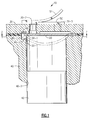
- each cylinder of compressor 10 has a suction valve 20 and a discharge valve 50, which are illustrated as reed valves, as well as a piston 42 which is located in bore 40-3.
- Discharge valve 50 has a backer 51 which limits the movement of valve 50 and is normally configured to dissipate the opening force applied to valve 50 via discharge passages 30-3 over its entire opening movement.
- suction valve 20 its tips 20-1 engage and deflect spring 60 when the valve 20 is in its closed position.
- tips 20-1 engage ledges 40-1 in recesses 40-2 in crankcase 40 which act as valve stops.
- Ledges 40-1 are engaged after an opening movement on the order of 0.1 inches, in order to minimize the clearance volume, with further opening movement by flexure of valve 20 as shown in phantom in Figure 1. Specifically, movement of valve 20 beyond contact with spring 60 is as a cantilevered beam until tips 20-1 engage ledges 40-1 and then flexure is in the form of a beam supported at both ends. As shown in phantom in Figure 1, valve 20 moves into bore 40-3.
- valve 20 tends to cause adhesion between valve 20 and seats 30-1 formed in valve plate 30.
- spring 60 provides an opening bias to valve 20 in addition to the fluid pressure differential acting across valve 20 at the start of the suction stroke. This bias tends to offset some, if not all, of the adhesion effects such that the opening of valve 20 on the suction stroke is essentially responsive solely to the differential fluid pressure across the valve.
- valve 20 would open at a higher differential pressure and tend to strike ledges or stops 40-1 at a higher velocity such as to facilitate flexure into bore 40-3 which, when coupled with the impinging flow from suction passages 30-2 can cause flexure of valve 20 beyond its yield strength and/or drive valve so far into bore 40-3 that tips 20-1 slip off of ledge or stops 40-1.
- each seat 30-1 is essentially a thinwalled cylinder having a flat, annular seating surface.
- a major consideration is to limit the location and thereby the width of oil film. Specifically, limiting the portion of seat 30-1 touching or in close proximity with valve 20 so as to maintain an oil film therebetween.
- the smaller the oil film the more easily it is ruptured with the consequence of opening earlier in the suction stroke at a lower differential pressure with a less violent opening and slower flow.
- valve 20 is seated on seat 30-1 against the bias of spring 60.
- Spring 60 is engaged by the suction valve 20 and compressed/deformed by the valve 20 as it is forced against the bias of spring 60 into seating engagement with seats 30-1 due to the differential pressure acting across valve 20 during the compression/discharge stroke. As illustrated in Figure 3, valve 20 is unseated and has just engaged spring 60. Although spring 60 has been illustrated as a leaf spring, other types of springs may be used.
Landscapes
- Engineering & Computer Science (AREA)
- General Engineering & Computer Science (AREA)
- Mechanical Engineering (AREA)
- Compressor (AREA)
- Check Valves (AREA)
Applications Claiming Priority (2)
| Application Number | Priority Date | Filing Date | Title |
|---|---|---|---|
| US60054 | 1998-04-15 | ||
| US09/060,054 US6099275A (en) | 1998-04-15 | 1998-04-15 | Biased open suction valve |
Publications (2)
| Publication Number | Publication Date |
|---|---|
| EP0950814A2 true EP0950814A2 (de) | 1999-10-20 |
| EP0950814A3 EP0950814A3 (de) | 2002-10-30 |
Family
ID=22027024
Family Applications (1)
| Application Number | Title | Priority Date | Filing Date |
|---|---|---|---|
| EP99630031A Withdrawn EP0950814A3 (de) | 1998-04-15 | 1999-03-26 | In der Ruhelage offengehaltenes, vorgespanntes Einlassventil |
Country Status (4)
| Country | Link |
|---|---|
| US (1) | US6099275A (de) |
| EP (1) | EP0950814A3 (de) |
| JP (1) | JP3085947B2 (de) |
| KR (1) | KR100342147B1 (de) |
Families Citing this family (7)
| Publication number | Priority date | Publication date | Assignee | Title |
|---|---|---|---|---|
| US7263153B2 (en) * | 2002-10-09 | 2007-08-28 | Marvell International, Ltd. | Clock offset compensator |
| BR0204413B1 (pt) * | 2002-10-09 | 2010-09-21 | válvula de sucção para compressor hermético de pequeno porte. | |
| JP4801409B2 (ja) * | 2005-10-06 | 2011-10-26 | 三菱重工業株式会社 | 低温流体用昇圧ポンプ |
| BRPI0505734A (pt) * | 2005-12-19 | 2007-09-25 | Brasil Compressores Sa | arranjo de montagem de válvula para compressor de refrigeração |
| JP5652613B2 (ja) * | 2011-03-08 | 2015-01-14 | サンデン株式会社 | 圧縮機の弁装置 |
| US20150226210A1 (en) * | 2014-02-10 | 2015-08-13 | General Electric Company | Linear compressor |
| JP7523935B2 (ja) * | 2020-04-06 | 2024-07-29 | 株式会社ミクニ | リードバルブ |
Citations (1)
| Publication number | Priority date | Publication date | Assignee | Title |
|---|---|---|---|---|
| US4580604A (en) | 1983-06-23 | 1986-04-08 | Mitsubishi Denki Kabushiki Kaisha | Discharging valve device for a compressor |
Family Cites Families (23)
| Publication number | Priority date | Publication date | Assignee | Title |
|---|---|---|---|---|
| US1834038A (en) * | 1929-12-31 | 1931-12-01 | Frigidaire Corp | Refrigerating apparatus |
| US2001885A (en) * | 1932-05-11 | 1935-05-21 | Kelvinator Corp | Refrigerating apparatus |
| US2020508A (en) * | 1934-06-25 | 1935-11-12 | Montgomery Ward & Co Inc | Valve mounting for refrigerator compressors |
| US2110107A (en) * | 1934-11-01 | 1938-03-01 | Walter J Sugden | Refrigerant compressor |
| US2372938A (en) * | 1942-11-12 | 1945-04-03 | Nash Kelvinator Corp | Refrigerating apparatus |
| US2981462A (en) * | 1956-07-09 | 1961-04-25 | Niedermayer Egon | Valve comprising a plurality of individual valves |
| DE3214713A1 (de) * | 1982-04-21 | 1983-10-27 | Wabco Westinghouse Fahrzeugbremsen GmbH, 3000 Hannover | Einrichtung zur erzeugung von druckgas |
| JPS607371A (ja) * | 1983-06-27 | 1985-01-16 | Bunjiro Ichijo | 広い周波数範囲の高安定,超低インピ−ダンスの容量,抵抗測定装置 |
| JPS607372A (ja) * | 1983-06-28 | 1985-01-16 | Nec Home Electronics Ltd | コンデンサの容量診断回路 |
| US4642037A (en) * | 1984-03-08 | 1987-02-10 | White Consolidated Industries, Inc. | Reed valve for refrigeration compressor |
| US4537566A (en) * | 1984-05-10 | 1985-08-27 | Copeland Corporation | Valve assembly for a compressor |
| JPS6165973A (ja) * | 1984-09-06 | 1986-04-04 | Mitsubishi Electric Corp | 圧縮機の冷媒吐出弁装置 |
| ES1000848Y (es) * | 1986-10-23 | 1988-11-01 | Goenaga Churruca Jose Maria | Dispositivo perfeccionado de valvula de aspiracion para compresores de aire |
| JPH0673866B2 (ja) * | 1988-07-18 | 1994-09-21 | 旭有機材工業株式会社 | フェノール樹脂発泡体の製造方法及びこれに用いる塗布装置 |
| JPH0261631A (ja) * | 1988-08-26 | 1990-03-01 | Yokogawa Medical Syst Ltd | 画像撮影装置 |
| US4955797A (en) * | 1989-02-15 | 1990-09-11 | Tecumseh Products Company | Valve indexing for a compressor |
| US5035050A (en) * | 1989-02-15 | 1991-07-30 | Tecumseh Products Company | Method of installing a valve assembly in a compressor |
| BR8901183A (pt) * | 1989-03-09 | 1990-10-16 | Brasil Compressores Sa | Valvula de descarga para compressor rotativo de pistao rolante |
| BR9002967A (pt) * | 1990-06-19 | 1991-12-24 | Brasil Compressores Sa | Valvula para compressor hermetico de refrigeracao |
| US5203686A (en) * | 1991-11-04 | 1993-04-20 | General Electric Company | Rotary compressor with span type discharge valve |
| JP3232839B2 (ja) * | 1993-12-24 | 2001-11-26 | 株式会社豊田自動織機 | 圧縮機の弁装置 |
| US5452994A (en) * | 1994-02-16 | 1995-09-26 | Thermo King Corporation | Refrigerant compressor |
| KR0170880B1 (ko) * | 1995-01-28 | 1999-03-30 | 김광호 | 왕복동형 압축기 |
-
1998
- 1998-04-15 US US09/060,054 patent/US6099275A/en not_active Expired - Fee Related
-
1999
- 1999-03-26 EP EP99630031A patent/EP0950814A3/de not_active Withdrawn
- 1999-04-13 JP JP11104677A patent/JP3085947B2/ja not_active Expired - Fee Related
- 1999-04-14 KR KR1019990013602A patent/KR100342147B1/ko not_active Expired - Fee Related
Patent Citations (1)
| Publication number | Priority date | Publication date | Assignee | Title |
|---|---|---|---|---|
| US4580604A (en) | 1983-06-23 | 1986-04-08 | Mitsubishi Denki Kabushiki Kaisha | Discharging valve device for a compressor |
Also Published As
| Publication number | Publication date |
|---|---|
| JP3085947B2 (ja) | 2000-09-11 |
| JPH11336664A (ja) | 1999-12-07 |
| EP0950814A3 (de) | 2002-10-30 |
| KR19990083268A (ko) | 1999-11-25 |
| KR100342147B1 (ko) | 2002-06-27 |
| US6099275A (en) | 2000-08-08 |
Similar Documents
| Publication | Publication Date | Title |
|---|---|---|
| US6309194B1 (en) | Enhanced oil film dilation for compressor suction valve stress reduction | |
| US6102680A (en) | Suction valve with release timing chamber | |
| US6565336B1 (en) | Normally unseated suction valve | |
| KR100196640B1 (ko) | 밀폐형 냉동 압축기용 밸브 | |
| EP0940582B1 (de) | Dilatation des Schmiermittels zur Reduzierung der Belastung des Kompressoreinlassventils | |
| US6099275A (en) | Biased open suction valve | |
| EP1586774A1 (de) | Verstellbarer taumelscheibenverdichter für überkritischen kältekreislauf | |
| EP0971129A3 (de) | Verdrängungskompressor für Kältemittel mit Ölabscheidungs- und Schmiersystem | |
| KR0156768B1 (ko) | 스크로울압축기의 첵밸브장치 | |
| US6044862A (en) | Compressor reed valve | |
| US6164334A (en) | Reed valve retention | |
| CN111656012B (zh) | 可变容量斜盘式压缩机 | |
| EP1120568A3 (de) | Gasverdichter | |
| KR100224022B1 (ko) | 밀폐형 압축기의 고효율 토출밸브 조립체 | |
| EP0971128A3 (de) | Verdrängungskompressor für Kältemittel mit Ölabscheidungs- und Schmiersystem | |
| JP2007146761A (ja) | 往復動圧縮機 | |
| EP1041284A2 (de) | Einlassventil für Kompressor |
Legal Events
| Date | Code | Title | Description |
|---|---|---|---|
| PUAI | Public reference made under article 153(3) epc to a published international application that has entered the european phase |
Free format text: ORIGINAL CODE: 0009012 |
|
| AK | Designated contracting states |
Kind code of ref document: A2 Designated state(s): AT BE CH CY DE DK ES FI FR GB GR IE IT LI LU MC NL PT SE |
|
| AX | Request for extension of the european patent |
Free format text: AL;LT;LV;MK;RO;SI |
|
| PUAL | Search report despatched |
Free format text: ORIGINAL CODE: 0009013 |
|
| AK | Designated contracting states |
Kind code of ref document: A3 Designated state(s): AT BE CH CY DE DK ES FI FR GB GR IE IT LI LU MC NL PT SE |
|
| AX | Request for extension of the european patent |
Free format text: AL;LT;LV;MK;RO;SI |
|
| 17P | Request for examination filed |
Effective date: 20021018 |
|
| 17Q | First examination report despatched |
Effective date: 20030129 |
|
| AKX | Designation fees paid |
Designated state(s): BE DE ES FR GB IT SE |
|
| STAA | Information on the status of an ep patent application or granted ep patent |
Free format text: STATUS: THE APPLICATION IS DEEMED TO BE WITHDRAWN |
|
| 18D | Application deemed to be withdrawn |
Effective date: 20030611 |