EP0951204B1 - Ballast - Google Patents
Ballast Download PDFInfo
- Publication number
- EP0951204B1 EP0951204B1 EP99106892A EP99106892A EP0951204B1 EP 0951204 B1 EP0951204 B1 EP 0951204B1 EP 99106892 A EP99106892 A EP 99106892A EP 99106892 A EP99106892 A EP 99106892A EP 0951204 B1 EP0951204 B1 EP 0951204B1
- Authority
- EP
- European Patent Office
- Prior art keywords
- ballast
- voltage
- lamp
- discharge lamp
- circuit
- Prior art date
- Legal status (The legal status is an assumption and is not a legal conclusion. Google has not performed a legal analysis and makes no representation as to the accuracy of the status listed.)
- Expired - Lifetime
Links
- 238000012544 monitoring process Methods 0.000 claims description 24
- 238000012806 monitoring device Methods 0.000 claims description 3
- 238000004880 explosion Methods 0.000 claims 1
- 238000010079 rubber tapping Methods 0.000 claims 1
- 239000003990 capacitor Substances 0.000 description 10
- 230000008878 coupling Effects 0.000 description 5
- 238000010168 coupling process Methods 0.000 description 5
- 238000005859 coupling reaction Methods 0.000 description 5
- 239000002360 explosive Substances 0.000 description 5
- 230000015556 catabolic process Effects 0.000 description 3
- 230000002950 deficient Effects 0.000 description 2
- 238000001514 detection method Methods 0.000 description 2
- 238000010586 diagram Methods 0.000 description 2
- 230000000712 assembly Effects 0.000 description 1
- 238000000429 assembly Methods 0.000 description 1
- 230000001419 dependent effect Effects 0.000 description 1
- 230000005669 field effect Effects 0.000 description 1
- 231100001261 hazardous Toxicity 0.000 description 1
- 230000007774 longterm Effects 0.000 description 1
- 239000000203 mixture Substances 0.000 description 1
- 230000001360 synchronised effect Effects 0.000 description 1
- 230000001960 triggered effect Effects 0.000 description 1
Images
Classifications
-
- H—ELECTRICITY
- H05—ELECTRIC TECHNIQUES NOT OTHERWISE PROVIDED FOR
- H05B—ELECTRIC HEATING; ELECTRIC LIGHT SOURCES NOT OTHERWISE PROVIDED FOR; CIRCUIT ARRANGEMENTS FOR ELECTRIC LIGHT SOURCES, IN GENERAL
- H05B41/00—Circuit arrangements or apparatus for igniting or operating discharge lamps
- H05B41/14—Circuit arrangements
- H05B41/26—Circuit arrangements in which the lamp is fed by power derived from DC by means of a converter, e.g. by high-voltage DC
- H05B41/28—Circuit arrangements in which the lamp is fed by power derived from DC by means of a converter, e.g. by high-voltage DC using static converters
- H05B41/282—Circuit arrangements in which the lamp is fed by power derived from DC by means of a converter, e.g. by high-voltage DC using static converters with semiconductor devices
- H05B41/285—Arrangements for protecting lamps or circuits against abnormal operating conditions
- H05B41/2851—Arrangements for protecting lamps or circuits against abnormal operating conditions for protecting the circuit against abnormal operating conditions
- H05B41/2855—Arrangements for protecting lamps or circuits against abnormal operating conditions for protecting the circuit against abnormal operating conditions against abnormal lamp operating conditions
-
- Y—GENERAL TAGGING OF NEW TECHNOLOGICAL DEVELOPMENTS; GENERAL TAGGING OF CROSS-SECTIONAL TECHNOLOGIES SPANNING OVER SEVERAL SECTIONS OF THE IPC; TECHNICAL SUBJECTS COVERED BY FORMER USPC CROSS-REFERENCE ART COLLECTIONS [XRACs] AND DIGESTS
- Y02—TECHNOLOGIES OR APPLICATIONS FOR MITIGATION OR ADAPTATION AGAINST CLIMATE CHANGE
- Y02B—CLIMATE CHANGE MITIGATION TECHNOLOGIES RELATED TO BUILDINGS, e.g. HOUSING, HOUSE APPLIANCES OR RELATED END-USER APPLICATIONS
- Y02B20/00—Energy efficient lighting technologies, e.g. halogen lamps or gas discharge lamps
-
- Y—GENERAL TAGGING OF NEW TECHNOLOGICAL DEVELOPMENTS; GENERAL TAGGING OF CROSS-SECTIONAL TECHNOLOGIES SPANNING OVER SEVERAL SECTIONS OF THE IPC; TECHNICAL SUBJECTS COVERED BY FORMER USPC CROSS-REFERENCE ART COLLECTIONS [XRACs] AND DIGESTS
- Y10—TECHNICAL SUBJECTS COVERED BY FORMER USPC
- Y10S—TECHNICAL SUBJECTS COVERED BY FORMER USPC CROSS-REFERENCE ART COLLECTIONS [XRACs] AND DIGESTS
- Y10S315/00—Electric lamp and discharge devices: systems
- Y10S315/05—Starting and operating circuit for fluorescent lamp
-
- Y—GENERAL TAGGING OF NEW TECHNOLOGICAL DEVELOPMENTS; GENERAL TAGGING OF CROSS-SECTIONAL TECHNOLOGIES SPANNING OVER SEVERAL SECTIONS OF THE IPC; TECHNICAL SUBJECTS COVERED BY FORMER USPC CROSS-REFERENCE ART COLLECTIONS [XRACs] AND DIGESTS
- Y10—TECHNICAL SUBJECTS COVERED BY FORMER USPC
- Y10S—TECHNICAL SUBJECTS COVERED BY FORMER USPC CROSS-REFERENCE ART COLLECTIONS [XRACs] AND DIGESTS
- Y10S315/00—Electric lamp and discharge devices: systems
- Y10S315/07—Starting and control circuits for gas discharge lamp using transistors
Definitions
- the invention relates to a ballast that for Parallel operation of discharge lamps set up and especially intended for security-relevant environments is.
- a circuit arrangement is known from EP 558 772 A1 to operate several fluorescent lamps with one known single ballast.
- the ballast points an inverter that has a symmetrical AC voltage emits at a fixed frequency.
- To the inverter are in parallel via current-limiting series chokes two fluorescent lamps connected.
- Both Fluorescent lamps come with a monitoring device connected, which determines whether on one of the fluorescent lamps the ignition voltage is longer than a predetermined period of time T1 is present.
- a switching relay between the fluorescent lamps and the series chokes allows both Fluorescent lamps in parallel to one of the ballasts to turn.
- the monitoring device now sets the Fault condition in which the ignition voltage at one of the Fluorescent lamps longer than the specified period this is interpreted as an error.
- the Switching relay otherwise the two fluorescent lamps each individually in line with the assigned ones Series chokes switches, now switches the fluorescent lamps in parallel to one of the series chokes.
- the inverter circuit contains two inverter half bridges, each are individually assigned to a gas discharge lamp. Each half-bridge inverter has two switching elements on. In addition, both gas discharge lamps are a bridge branch assigned together, which contains two capacitors. The gas discharge lamps are switched on by appropriate monitoring circuits individually monitored, with the appropriate assigned inverter bridges then individually can be controlled.
- DE-A-19518096 is an electronic one Ballast known to operate two gas discharge lamps is set up.
- the ballast has one Inverter half bridge on both gas discharge lamps powered.
- To deactivate a non-ignitable A lamp circuit is provided that detects the ignition pulses keeps away from the defective lamp.
- the ballast according to the invention allows the voltage applied to a failed fluorescent lamp decrease to zero when the lamp is not lit.
- the ballast has one according to the invention Inverters with multiple line branches, one of which at least one line branch both lamps together and at least two line branches each lamp are assigned separately.
- Such an inverter unlike two completely independent from each other unmeshed inverters, saving components build up. On the one hand, this serves the operational safety of the Ballast because failures decrease with the number of components become less likely. On the other hand this represents a cost and space saving.
- the ballast preferably contains a mains-powered one Voltage source that is a predeterminable or a delivers predetermined DC voltage. This can ensure that the power implemented on a lamp does not change if the other lamp fails.
- the inverter is of a particularly simple design formed by two half bridges, the one Share switching element. That way you can two or more half bridges are combined, with only one for each additional half-bridge additional switching element and possibly a decoupling element is appropriate. As such, for example Serve diodes.
- the inverter becomes a total through three switching transistors and two decoupling diodes educated.
- Each discharge lamp can have one separately Ignition circuit must be assigned. This gives until ignition the discharge lamp and / or until a maximum has expired Ignition duration high voltage or ignition voltage pulses the discharge lamp. So that both discharge lamps ignite independently.
- the inverter concept according to the invention is like this carried out that the discharge lamps with separate current limits, For example, chokes are provided. This is in Especially with regard to the failure of one of the discharge lamps expedient because the remaining lamp then with the predetermined performance continues to burn. It makes it possible the inverter concept according to the invention, for both Discharge lamps with a single control circuit that drives the inverter.
- the ballast is preferably at a fixed frequency operated to ignite to another frequency is moved.
- the discharge lamp is preferred arranged in a resonant circuit that when ignited near its resonance frequency and with normal lamp operation works apart from it. However, it also exists the possibility, with appropriate design of the lamp circle only with a fixed frequency of the lamp circuit work.
- Each is preferably a discharge lamp a separate, belonging to the monitoring circuit Associated monitor device that checks how long the ignition voltage generated by excessive resonance at the Discharge lamp is present. If the time exceeds a set Limit, the relevant lamp-specific Branch of the inverter shut down.
- At least one point in time is checked whether the lamp voltage to the burning voltage, i.e. below a value above the burning voltage collapsed is. If not, the discharge lamp is considered not ignited.
- the monitoring circuit remains after one time Detection of a state in which a discharge lamp does not ignite when locked. This condition will preferably maintained until the mains voltage of the ballast is disconnected. This can be done with a corresponding mains-operated reset device. It is possible to only trigger the reset, if the mains voltage has been interrupted for a minimum time. A timer can be used for this.
- the monitoring circuit can also by other means, for example a separate one Switch or a detection device, reset that recognizes the replacement of the discharge lamp.
- a tap circuit for the power supply of the Control circuit is preferably at least double and connected to the lamp-specific branches of the inverter connected.
- the tap circuit indicates their input usually capacitive behavior.
- the capacitive load of the shared inverter branch kept low, what its switching losses in Limits are kept or minimized. This applies in particular to Embodiments with decoupling elements between the Lamp choke and the switching element of the common branch of the inverter.
- ballasts wear that for direct ignition of the discharge lamps without Preheating the electrodes are set up. Here you can considerable ignition voltage increases occur which lead to Unheated ignition of the discharge lamps are required. It is for operation in potentially explosive environments of particular advantage here if the permanent stock such excessive voltage can be avoided.
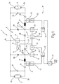
- Fig. 1 is a ballast 1 for the operation of two Discharge lamps 2, 3 illustrated.
- the discharge lamps 2, 3 are low pressure gas discharge lamps, for example Fluorescent lamps with helical electrodes.
- the ballast 1 and the discharge lamps 2, 3 are for use in hazardous areas intended.
- the electrodes 2a, 2b, 3a, 3b of the discharge lamps 2, 3 can be dispensed with the ballast 1 for the ignition of the discharge lamps 2, 3 set up by means of voltage breakdown.
- Corresponding the electrodes 2a, 2b, 3a, 3b are outside the Discharge lamps 2, 3, for example in the lamp holders, shorted.
- the power supply for the discharge lamps 2, 3 serves the ballast 1, one in the present Embodiment of three line branches 5, 6, 7 formed inverter 8 has.
- Line branch 5 is directly connected to a supply voltage VDC, the circuit parts not illustrated further built up and for example from a mains voltage is derived.
- the supply voltage VDC is one DC voltage with preferably constant size. With the The supply voltage VDC are also the electrodes 2a, 3a of the discharge lamps 2, 3 connected.
- a switching transistor 11 is arranged, for example a bipolar transistor or a MOS-FET can.
- Its control electrode 12 is with a control circuit 14 connected, which outputs an AC voltage, whose frequency for the operation of the lamps a first predetermined fixed value and for igniting the discharge lamps 2, 3 a different second predetermined Assumes value.
- the switching element 11 of the line branch 5 opens and closes accordingly in time with the time-symmetrical control voltage.
- the line branch 5 is two discharge lamps 2, 3 assigned together. With the line branch 5 is the Line branch 6 connected in series to ground.
- the Line branch 6 contains a switching element 15 through a switching transistor, for example a bipolar transistor or a MOS-FET or other field effect transistor can be formed. With the switching element 15, a decoupling diode 16 is connected in series, whose polarity is selected so that with a conductive switching element 11 a current flow via the line branch 5 to the Discharge lamp 2 is possible. In the present example 16 is on the switching element 15.
- the Connection point between the cathode of the diode 16 and the Switching element 15 is via a current limiting choke 17 and a coupling capacitor 18 to the electrode 2b of the Discharge lamp 2 switched.
- the line branch 6 is the discharge lamp 2 alone assigned.
- To control its switching element 15 is at its control electrode 19 for operating the discharge lamp 2 the AC voltage output by the control circuit 14 created.
- This is a corresponding one Line 21 and a gate circuit 22 of the control electrode 19 fed.
- the gate circuit 22 can by a gate, a controllable amplifier or an electronic one Switch be formed. It has a lock entrance 23 which, when supplied with a lock signal, the Output of the gate circuit 22 and thus the control input 19 of the switching element 15 is at a potential at which the Switching element 15 locks securely.
- the line branch 7 is assigned to the discharge lamp 3. It has a switching element 25 and one with it Decoupling element connected in series in the direction of flow 26 on, in the present example by a diode is formed. At the connection point between the diode 26 and the switching element 25 is via a decoupling choke 27 and a coupling capacitor 28 the discharge lamp 3, i.e. whose electrode 3b connected.
- the switching element 25 has a control input 29 on the via a gate circuit 32 with the line 21 and thus with the output from the control circuit 14 Control AC voltage is connected. Even the gate circuit 32 has a control input 33 which, when activated the output of the gate circuit to a potential lets go, in which the switching element 25 is securely locked is.
- the switching elements 15, 25 are synchronized with each other driven in phase opposition to the switching element 11.
- the line branches 6, 7 are independent can be deactivated or activated from one another, see above that the discharge lamps 2, 3 are independent of each other can be deactivated.
- the gate circuits 22, 32 belong to a monitoring circuit 36, which monitors the lamp voltages.
- the voltages dropping at the discharge lamps 2, 3 take relatively before the discharge lamps 2, 3 are ignited high values that are required to be in the discharge lamps 2, 3 bring about a voltage breakdown.
- the discharge lamps 2, 3 have capacitors 37, 38 connected in parallel, for example above the normal operating frequency with the current limiting chokes 17, 27 a series resonant circuit form.
- the time monitoring assembly 41 contains a rectifier which is the one at the connection point tapped AC voltage converted into a DC voltage.
- the time monitoring assembly 41 also contains a threshold switch that emits a signal when the rectified AC voltage exceeds a threshold.
- the threshold is set so that it is clearly below if the discharge lamp 2 in Burning operation works, but is clearly exceeded, if 2 ignition voltage is present at the discharge lamp.
- On the threshold switch is followed by a timer, which at Exceeding the threshold is triggered and on which Output of the monitoring module 41 emits a signal, if the threshold is exceeded for longer than one preset time t has taken.
- a threshold switch 42 as a memory serving RS flip-flop 43 connected with a set input.
- the output is with the control input 23 of the gate circuit 22 connected.
- the RS flip-flop circuit has also a reset input to that with a reset circuit 44 is connected. This gives a reset signal when the line voltage is longer than a predetermined one Period was switched off.
- the monitoring circuit 36 has corresponding assemblies, namely a time monitoring circuit 51 and one downstream threshold circuit 52 and an RS flip-flop 53 on.
- the interconnection corresponds to the interconnection the elements for monitoring the discharge lamp 2.
- the time monitoring circuit 41, 51 can also internally be otherwise procured. It is essential that they are on outputs its signal when the ignition voltage longer than a predetermined time on the respective discharge lamp 2, 3 is present. This can also be the case, for example can be achieved by a circuit after switching on the mains voltage for a preset or preset time t no signal passes and only after this period at their exit Emits a signal the size of which is present at its input AC voltage corresponds. The output signal is then checked by the threshold switches 42, 52, whether it is above or below a switching threshold lies.
- the monitoring circuit 36 and the drive circuit 14 need an operating voltage that is clear below the operating voltage VDC of the inverter 8 lies.
- To generate this auxiliary voltage VH are the Line branches 6 and 7 each with a capacitor 56, 57 tapped with one end at the connection point between the respective diode 16, 26 and the switching element 15, 25 is connected. From this point leads also a free-wheeling diode 58, 59 against the operating voltage VDC of the inverter 8.
- the tap capacitors 56, 57 directly on The end of the current limiting chokes 17, 27 becomes the capacitive Load on the switching element 11 kept low, what whose switching losses are minimized.
- the Input of the inverter 8 the voltage VDC.
- the control circuit 14 now initially works with an ignition frequency, with which the inverter 8 is controlled.
- the timer circuit 44 transfers the RS flip-flops 43, 53 at Switch on in a defined state, in which the Enable gate circuits 22, 32.
- the driving impulses arrive from the control circuit 14 to the switching elements 15, 25.
- the switching element 11 works in push-pull to the switching elements 15, 25 with the ignition frequency, in which from the series chokes 17, 27 and Capacitors 37, 38 formed series resonant circuits in Resonance come.
- At the discharge lamps 2, 3 arises by increasing the resonance at the series resonance circuits relatively high ignition voltage. This leads within one predetermined ignition time for operational discharge lamps 2, 3 for voltage breakdown and thus for igniting the same.
- a set time t preferably is slightly less than the time for which the control circuit Delivers 14 control pulses with ignition frequency, but if necessary also equal to or larger than this time can be checked by the monitoring circuit 36 the voltage across the discharge lamps 2, 3 and Coupling capacitors 18, 28. Is the voltage clear greater than the burning voltage of an ignited discharge lamp 2, 3, this is seen as a signal that the Discharge lamp 2 or 3 has not ignited.
- Corresponding the corresponding RS flip-flop 43 or 53 receives a set signal, whereupon there is the respective assigned gate circuit 22, 32 turns off. Subsequently, if not ignited the discharge lamp 2, the switching element 15 and when not ignited the discharge lamp 3, the switching element 25 none Driving impulses more. The discharge lamp in question 2 or 3 is therefore no longer supplied with voltage and the voltage dropping across the respective discharge lamp 2, 3 becomes zero while the other discharge lamp 2, 3 continues to burn when ignited Has.
Landscapes
- Circuit Arrangements For Discharge Lamps (AREA)
- Mixers With Rotating Receptacles And Mixers With Vibration Mechanisms (AREA)
Claims (12)
- Ballast (1) pour le fonctionnement en parallèle de lampes à décharge gazeuse (2, 3), en particulier pour des atmosphères explosives, avec un onduleur (8) qui comporte dans ses branches de circuit (5, 6, 7) des entrées de commande pilotées par des éléments de commutation (11, 15, 25),avec un circuit de commande (14) qui est connecté aux entrées de commande de l'onduleur (8) et met en et hors service les éléments de commutation (11, 15, 25),au moins deux branches de circuit (6, 7) étant prévues, qui sont associées chacune à seulement une lampe à décharge gazeuse (2 ou 3),

avec un circuit de surveillance (36), qui surveille les tensions de lampe indépendamment les unes des autres afin de déterminer si la durée d'application de la tension d'amorçage est supérieure à une durée prédéterminée et, à l'aide du circuit de commande (14), bloque la commande d'au moins l'élément de commutation (15 ou 25), qui est disposé dans la branche de circuit (6, 7) associée à la lampe à décharge gazeuse (2, 3) pour laquelle une tension supérieure à la tension d'éclairage a été déterminée à un instant donné, postérieur d'un certain laps de temps à la mise sous tension, qui est plus grand qu'une durée d'amorçage définie. - Ballast selon la revendication 1, caractérisé en ce que la tension mesurée supérieure à la tension d'éclairage, de préférence, est située sensiblement au milieu entre la tension d'éclairage de la lampe à décharge gazeuse (2,3) et la tension d'amorçage.
- Ballast selon la revendication 1, caractérisé en ce que le ballast (1) comporte une source de tension qui délivre une tension continue prédéterminée.
- Ballast selon la revendication 1, caractérisé en ce que la branche commune (5) fait partie à la fois d'un premier demi-pont pour alimenter une première lampe à décharge gazeuse (2) et d'au moins un demi-pont supplémentaire assurant l'alimentation d'au moins une lampe à décharge (3) supplémentaire.
- Ballast selon la revendication 1, caractérisé en ce que les éléments de découplage (16, 26) sont des diodes.
- Ballast selon la revendication 1, caractérisé en ce qu'un circuit d'amorçage séparé est associé à chacune des lampes à décharge gazeuse (2, 3).
- Ballast selon la revendication 1, caractérisé en ce qu'un moyen de limitation de courant (17, 27) séparé est associé à chacune des lampes à décharge gazeuse (2,3).
- Ballast selon la revendication 1, caractérisé en ce qu'un système de moniteur (41, 51) appartenant au circuit de surveillance (36) est associé à chacune des lampes à décharge gazeuse (2,3).
- Ballast selon la revendication 1, caractérisé en ce que le circuit de surveillance (36) comprend un dispositif d'accumulateur (43, 53) à l'aide duquel peut être maintenu un état bloquant, dans lequel la partie de l'onduleur (8) spécifique à la lampe est amenée par le dispositif de surveillance lors de la détection d'un état de défaut caractérisé.
- Ballast selon la revendication 1, caractérisé en ce que le circuit de surveillance (36) est relié à un dispositif de réinitialisation (44), par lequel l'onduleur (8) peut être réactivé après un blocage partiel consécutif à un défaut au niveau de la lampe à décharge gazeuse (2, 3).
- Ballast selon la revendication 1, caractérisé en ce qu'un circuit de piquage (56, 57) qui assure l'alimentation en courant du circuit de commande (14) est connecté aux branches (6, 7) de l'onduleur (8), spécifiques des lampes (6, 7).
- Ballast selon la revendication 1, caractérisé en ce que le ballast (1) est agencé pour l'amorçage des lampes à décharge gazeuse (2, 3) par une décharge de tension au niveau d'électrodes froides (2a, 2b ; 3a, 3b).
Applications Claiming Priority (2)
| Application Number | Priority Date | Filing Date | Title |
|---|---|---|---|
| DE19816815 | 1998-04-16 | ||
| DE19816815A DE19816815C1 (de) | 1998-04-16 | 1998-04-16 | Vorschaltgerät zum Betrieb einer Mehrzahl von Entladungslampen |
Publications (3)
| Publication Number | Publication Date |
|---|---|
| EP0951204A2 EP0951204A2 (fr) | 1999-10-20 |
| EP0951204A3 EP0951204A3 (fr) | 2001-05-09 |
| EP0951204B1 true EP0951204B1 (fr) | 2003-09-17 |
Family
ID=7864684
Family Applications (1)
| Application Number | Title | Priority Date | Filing Date |
|---|---|---|---|
| EP99106892A Expired - Lifetime EP0951204B1 (fr) | 1998-04-16 | 1999-04-08 | Ballast |
Country Status (6)
| Country | Link |
|---|---|
| US (1) | US6147462A (fr) |
| EP (1) | EP0951204B1 (fr) |
| JP (1) | JPH11329771A (fr) |
| AT (1) | ATE250319T1 (fr) |
| DE (2) | DE19816815C1 (fr) |
| ES (1) | ES2202955T3 (fr) |
Cited By (1)
| Publication number | Priority date | Publication date | Assignee | Title |
|---|---|---|---|---|
| US8421389B2 (en) | 2006-06-15 | 2013-04-16 | Lenze Drives Gmbh | Driving with inverters with low switching losses |
Families Citing this family (4)
| Publication number | Priority date | Publication date | Assignee | Title |
|---|---|---|---|---|
| US7336041B2 (en) * | 2004-12-06 | 2008-02-26 | Vicente Aldape Ayala | Automatic light dimmer for electronic and magnetic ballasts (fluorescent or HID) |
| DE102007054806A1 (de) | 2007-11-16 | 2009-05-20 | Tridonicatco Schweiz Ag | Betriebsschaltung für in Serie geschaltete Leuchtmittel, insbesondere HID-Gasentladungslampen |
| DE102011050306B3 (de) * | 2011-05-12 | 2012-11-08 | Vossloh-Schwabe Deutschland Gmbh | Wechselrichterschaltung und Verfahren zur Speisung mehrerer Lampenkreise |
| DE102015211207A1 (de) | 2015-06-18 | 2016-12-22 | Tridonic Gmbh & Co Kg | Mehrkanal-LED-Konverter und Verfahren zu dessen Betreiben |
Family Cites Families (12)
| Publication number | Priority date | Publication date | Assignee | Title |
|---|---|---|---|---|
| US4349748A (en) * | 1979-03-21 | 1982-09-14 | Dynascan Corporation | Timer and power control system |
| FI61114C (fi) * | 1981-03-30 | 1982-05-10 | Kalervo Virtanen | Anordning foer reglering av effekten i elektriska apparater isynnerhet i lysroer |
| US4554487A (en) * | 1983-05-17 | 1985-11-19 | Nilssen Ole K | Electronic fluorescent lamp ballast with overload protection |
| ATE120331T1 (de) * | 1989-04-28 | 1995-04-15 | Philips Electronics Nv | Wechselrichter zum speisen zweier gas und / oder dampfentladungslampen. |
| DE3925654A1 (de) * | 1989-08-03 | 1991-02-07 | Schmidt Michael | Steuergeraet fuer wenigstens eine entladungslampe |
| US5729097A (en) * | 1990-11-29 | 1998-03-17 | Holzer; Walter | Method and device for controlling electric discharge lamps with electronic fluorescent lamp ballasts |
| ATE143208T1 (de) * | 1992-03-02 | 1996-10-15 | Siemens Ag | Schaltungsanordnung zum betreiben mehrerer leuchtstofflampen mit einem vorschaltgerät |
| US5363018A (en) * | 1993-09-16 | 1994-11-08 | Motorola Lighting, Inc. | Ballast circuit equipped with ground fault detector |
| DE19518096A1 (de) * | 1995-05-17 | 1996-11-21 | Ceag Sicherheitstechnik Gmbh | Elektronisches Vorschaltgerät und dessen Betriebsverfahren |
| US5636111A (en) * | 1996-03-26 | 1997-06-03 | The Genlyte Group Incorporated | Ballast shut-down circuit responsive to an unbalanced load condition in a single lamp ballast or in either lamp of a two-lamp ballast |
| DE19715342C1 (de) * | 1997-04-12 | 1998-12-17 | Vossloh Schwabe Gmbh | Vorschaltgerät für unabhängigen Parallelbetrieb von Niederdruck-Gasentladungslampen |
| US5959408A (en) * | 1997-08-07 | 1999-09-28 | Magnetek, Inc. | Symmetry control circuit for pre-heating in electronic ballasts |
-
1998
- 1998-04-16 DE DE19816815A patent/DE19816815C1/de not_active Expired - Fee Related
-
1999
- 1999-04-08 ES ES99106892T patent/ES2202955T3/es not_active Expired - Lifetime
- 1999-04-08 EP EP99106892A patent/EP0951204B1/fr not_active Expired - Lifetime
- 1999-04-08 DE DE59906982T patent/DE59906982D1/de not_active Expired - Lifetime
- 1999-04-08 AT AT99106892T patent/ATE250319T1/de active
- 1999-04-14 JP JP11106952A patent/JPH11329771A/ja active Pending
- 1999-04-16 US US09/292,931 patent/US6147462A/en not_active Expired - Fee Related
Cited By (1)
| Publication number | Priority date | Publication date | Assignee | Title |
|---|---|---|---|---|
| US8421389B2 (en) | 2006-06-15 | 2013-04-16 | Lenze Drives Gmbh | Driving with inverters with low switching losses |
Also Published As
| Publication number | Publication date |
|---|---|
| EP0951204A2 (fr) | 1999-10-20 |
| EP0951204A3 (fr) | 2001-05-09 |
| DE59906982D1 (de) | 2003-10-23 |
| US6147462A (en) | 2000-11-14 |
| ATE250319T1 (de) | 2003-10-15 |
| JPH11329771A (ja) | 1999-11-30 |
| DE19816815C1 (de) | 1999-11-11 |
| ES2202955T3 (es) | 2004-04-01 |
Similar Documents
| Publication | Publication Date | Title |
|---|---|---|
| DE4109325C2 (de) | Schaltungsanordnung zum Betrieb einer Hochdruck-Entladungslampe | |
| DE4129557C2 (de) | Stromversorgungsschaltung für eine Gasentladungslampe in einem Fahrzeug | |
| DE69019648T2 (de) | Gerät zur Versorgung einer Leuchtstofflampe. | |
| DE4002334C2 (de) | Schaltung zum Betreiben einer elektrischen Entladelampe in einem Kraftfahrzeug | |
| DE60125214T2 (de) | Ballaststeuer-ic mit leistungsfaktorkorrektur | |
| DE69530143T2 (de) | Schutzschaltung für Bogenentladungslampen | |
| DE60037861T2 (de) | Projektionslampe und Verfahren zur Regulierung ihrer Helligkeit | |
| DE69428866T2 (de) | Vorschaltgerät für eine Entladungslampe, mit Arbeitsfähigkeitsanzeige | |
| DE10196562B4 (de) | Vorschaltgerät für den Betrieb einer Entladungslampe | |
| CH663508A5 (de) | Elektronisches vorschaltgeraet fuer fluoreszenzlampen sowie verfahren zu dessen betrieb. | |
| DE19705776A1 (de) | Beleuchtungsschaltkreis für eine Entladungslampe | |
| DE69327426T2 (de) | Überwachungsgerät für eine Leuchtstoffröhre | |
| DE69725821T2 (de) | Vorschaltgerät | |
| DE19713935B4 (de) | Stromversorgungsschaltung für eine Entladungslampe | |
| EP3048721A1 (fr) | Dispositif et procede de commande fiable d'un circuit semi-conducteur d'un onduleur | |
| DE19801133B4 (de) | Versorgungsschaltung mit Schutzschaltung für eine Entladungslampe | |
| DE69017940T2 (de) | Wechselrichter zum Speisen zweier Gas und / oder Dampfentladungslampen. | |
| EP0951204B1 (fr) | Ballast | |
| DE2818242C2 (fr) | ||
| EP0871348A1 (fr) | Ballast pour l'opération parallèle indépendante de lampes luminescentes à gaz de basse pression | |
| DE69702896T2 (de) | Stromversorgung für Entladungslampen mit Ueberspannungsschutz | |
| EP0871347B1 (fr) | Ballast à réamorçage automatique | |
| DE10240110A1 (de) | Entladungslampen-Beleuchtungsschaltung | |
| DE60009222T2 (de) | Regelvorrichtung einer leuchtstofflampe | |
| EP0558772B1 (fr) | Circuit pour le fonctionnement de plusieurs lampes fluorescentes avec un ballast |
Legal Events
| Date | Code | Title | Description |
|---|---|---|---|
| PUAI | Public reference made under article 153(3) epc to a published international application that has entered the european phase |
Free format text: ORIGINAL CODE: 0009012 |
|
| AK | Designated contracting states |
Kind code of ref document: A2 Designated state(s): AT BE CH DE DK ES FI FR GB GR IE IT LI NL PT SE |
|
| AX | Request for extension of the european patent |
Free format text: AL;LT;LV;MK;RO;SI |
|
| RAP1 | Party data changed (applicant data changed or rights of an application transferred) |
Owner name: VOSSLOH-SCHWABE ELEKTRONIK GMBH |
|
| PUAL | Search report despatched |
Free format text: ORIGINAL CODE: 0009013 |
|
| AK | Designated contracting states |
Kind code of ref document: A3 Designated state(s): AT BE CH CY DE DK ES FI FR GB GR IE IT LI LU MC NL PT SE |
|
| AX | Request for extension of the european patent |
Free format text: AL;LT;LV;MK;RO;SI |
|
| 17P | Request for examination filed |
Effective date: 20010712 |
|
| AKX | Designation fees paid |
Free format text: AT BE CH DE DK ES FI FR GB GR IE IT LI NL PT SE |
|
| RIN1 | Information on inventor provided before grant (corrected) |
Inventor name: DIE ERFINDER HABEN AUF IHRE NENNUNG VERZICHTET |
|
| 17Q | First examination report despatched |
Effective date: 20020218 |
|
| RIC1 | Information provided on ipc code assigned before grant |
Free format text: 7H 05B 41/285 A |
|
| GRAH | Despatch of communication of intention to grant a patent |
Free format text: ORIGINAL CODE: EPIDOS IGRA |
|
| GRAH | Despatch of communication of intention to grant a patent |
Free format text: ORIGINAL CODE: EPIDOS IGRA |
|
| GRAA | (expected) grant |
Free format text: ORIGINAL CODE: 0009210 |
|
| AK | Designated contracting states |
Kind code of ref document: B1 Designated state(s): AT BE CH DE DK ES FI FR GB GR IE IT LI NL PT SE |
|
| PG25 | Lapsed in a contracting state [announced via postgrant information from national office to epo] |
Ref country code: NL Free format text: LAPSE BECAUSE OF FAILURE TO SUBMIT A TRANSLATION OF THE DESCRIPTION OR TO PAY THE FEE WITHIN THE PRESCRIBED TIME-LIMIT Effective date: 20030917 Ref country code: IE Free format text: LAPSE BECAUSE OF FAILURE TO SUBMIT A TRANSLATION OF THE DESCRIPTION OR TO PAY THE FEE WITHIN THE PRESCRIBED TIME-LIMIT Effective date: 20030917 Ref country code: GB Free format text: LAPSE BECAUSE OF FAILURE TO SUBMIT A TRANSLATION OF THE DESCRIPTION OR TO PAY THE FEE WITHIN THE PRESCRIBED TIME-LIMIT Effective date: 20030917 Ref country code: FI Free format text: LAPSE BECAUSE OF FAILURE TO SUBMIT A TRANSLATION OF THE DESCRIPTION OR TO PAY THE FEE WITHIN THE PRESCRIBED TIME-LIMIT Effective date: 20030917 |
|
| REG | Reference to a national code |
Ref country code: GB Ref legal event code: FG4D Free format text: NOT ENGLISH |
|
| REG | Reference to a national code |
Ref country code: CH Ref legal event code: NV Representative=s name: KEMENY AG PATENTANWALTBUERO Ref country code: CH Ref legal event code: EP |
|
| REF | Corresponds to: |
Ref document number: 59906982 Country of ref document: DE Date of ref document: 20031023 Kind code of ref document: P |
|
| REG | Reference to a national code |
Ref country code: IE Ref legal event code: FG4D Free format text: GERMAN |
|
| PG25 | Lapsed in a contracting state [announced via postgrant information from national office to epo] |
Ref country code: SE Free format text: LAPSE BECAUSE OF FAILURE TO SUBMIT A TRANSLATION OF THE DESCRIPTION OR TO PAY THE FEE WITHIN THE PRESCRIBED TIME-LIMIT Effective date: 20031217 Ref country code: GR Free format text: LAPSE BECAUSE OF FAILURE TO SUBMIT A TRANSLATION OF THE DESCRIPTION OR TO PAY THE FEE WITHIN THE PRESCRIBED TIME-LIMIT Effective date: 20031217 Ref country code: DK Free format text: LAPSE BECAUSE OF FAILURE TO SUBMIT A TRANSLATION OF THE DESCRIPTION OR TO PAY THE FEE WITHIN THE PRESCRIBED TIME-LIMIT Effective date: 20031217 |
|
| PG25 | Lapsed in a contracting state [announced via postgrant information from national office to epo] |
Ref country code: PT Free format text: LAPSE BECAUSE OF FAILURE TO SUBMIT A TRANSLATION OF THE DESCRIPTION OR TO PAY THE FEE WITHIN THE PRESCRIBED TIME-LIMIT Effective date: 20031226 |
|
| NLV1 | Nl: lapsed or annulled due to failure to fulfill the requirements of art. 29p and 29m of the patents act | ||
| GBV | Gb: ep patent (uk) treated as always having been void in accordance with gb section 77(7)/1977 [no translation filed] |
Effective date: 20030917 |
|
| REG | Reference to a national code |
Ref country code: ES Ref legal event code: FG2A Ref document number: 2202955 Country of ref document: ES Kind code of ref document: T3 |
|
| REG | Reference to a national code |
Ref country code: IE Ref legal event code: FD4D |
|
| PG25 | Lapsed in a contracting state [announced via postgrant information from national office to epo] |
Ref country code: BE Free format text: LAPSE BECAUSE OF NON-PAYMENT OF DUE FEES Effective date: 20040430 |
|
| ET | Fr: translation filed | ||
| PLBE | No opposition filed within time limit |
Free format text: ORIGINAL CODE: 0009261 |
|
| STAA | Information on the status of an ep patent application or granted ep patent |
Free format text: STATUS: NO OPPOSITION FILED WITHIN TIME LIMIT |
|
| 26N | No opposition filed |
Effective date: 20040618 |
|
| BERE | Be: lapsed |
Owner name: *VOSSLOH-SCHWABE ELEKTRONIK G.M.B.H. Effective date: 20040430 |
|
| REG | Reference to a national code |
Ref country code: CH Ref legal event code: PUE Owner name: VOSSLOH-SCHWABE DEUTSCHLAND GMBH Free format text: VOSSLOH-SCHWABE ELEKTRONIK GMBH#WASENSTR. 25#73660 URBACH (DE) -TRANSFER TO- VOSSLOH-SCHWABE DEUTSCHLAND GMBH#WASENSTRASSE 25#73660 URBACH (DE) |
|
| REG | Reference to a national code |
Ref country code: FR Ref legal event code: TP |
|
| PGFP | Annual fee paid to national office [announced via postgrant information from national office to epo] |
Ref country code: CH Payment date: 20120420 Year of fee payment: 14 |
|
| PGFP | Annual fee paid to national office [announced via postgrant information from national office to epo] |
Ref country code: ES Payment date: 20120425 Year of fee payment: 14 |
|
| PGFP | Annual fee paid to national office [announced via postgrant information from national office to epo] |
Ref country code: AT Payment date: 20120411 Year of fee payment: 14 |
|
| REG | Reference to a national code |
Ref country code: CH Ref legal event code: PL |
|
| PG25 | Lapsed in a contracting state [announced via postgrant information from national office to epo] |
Ref country code: CH Free format text: LAPSE BECAUSE OF NON-PAYMENT OF DUE FEES Effective date: 20130430 Ref country code: LI Free format text: LAPSE BECAUSE OF NON-PAYMENT OF DUE FEES Effective date: 20130430 |
|
| PGFP | Annual fee paid to national office [announced via postgrant information from national office to epo] |
Ref country code: FR Payment date: 20140422 Year of fee payment: 16 Ref country code: IT Payment date: 20140430 Year of fee payment: 16 |
|
| REG | Reference to a national code |
Ref country code: AT Ref legal event code: MM01 Ref document number: 250319 Country of ref document: AT Kind code of ref document: T Effective date: 20140408 |
|
| PG25 | Lapsed in a contracting state [announced via postgrant information from national office to epo] |
Ref country code: AT Free format text: LAPSE BECAUSE OF NON-PAYMENT OF DUE FEES Effective date: 20140408 |
|
| PG25 | Lapsed in a contracting state [announced via postgrant information from national office to epo] |
Ref country code: IT Free format text: LAPSE BECAUSE OF NON-PAYMENT OF DUE FEES Effective date: 20150408 |
|
| REG | Reference to a national code |
Ref country code: FR Ref legal event code: ST Effective date: 20151231 |
|
| PG25 | Lapsed in a contracting state [announced via postgrant information from national office to epo] |
Ref country code: FR Free format text: LAPSE BECAUSE OF NON-PAYMENT OF DUE FEES Effective date: 20150430 |
|
| PG25 | Lapsed in a contracting state [announced via postgrant information from national office to epo] |
Ref country code: ES Free format text: LAPSE BECAUSE OF NON-PAYMENT OF DUE FEES Effective date: 20140409 |
|
| PGFP | Annual fee paid to national office [announced via postgrant information from national office to epo] |
Ref country code: DE Payment date: 20160226 Year of fee payment: 18 |
|
| REG | Reference to a national code |
Ref country code: DE Ref legal event code: R119 Ref document number: 59906982 Country of ref document: DE |
|
| PG25 | Lapsed in a contracting state [announced via postgrant information from national office to epo] |
Ref country code: DE Free format text: LAPSE BECAUSE OF NON-PAYMENT OF DUE FEES Effective date: 20171103 |