EP0951246B1 - Elastisch verformbares osteosynthesesystem für die wirbelsäule - Google Patents
Elastisch verformbares osteosynthesesystem für die wirbelsäule Download PDFInfo
- Publication number
- EP0951246B1 EP0951246B1 EP97945916A EP97945916A EP0951246B1 EP 0951246 B1 EP0951246 B1 EP 0951246B1 EP 97945916 A EP97945916 A EP 97945916A EP 97945916 A EP97945916 A EP 97945916A EP 0951246 B1 EP0951246 B1 EP 0951246B1
- Authority
- EP
- European Patent Office
- Prior art keywords
- axis
- intermediate portion
- link member
- deformation
- fixing portions
- Prior art date
- Legal status (The legal status is an assumption and is not a legal conclusion. Google has not performed a legal analysis and makes no representation as to the accuracy of the status listed.)
- Expired - Lifetime
Links
- 230000005489 elastic deformation Effects 0.000 title description 2
- 238000005452 bending Methods 0.000 claims abstract description 9
- 238000013519 translation Methods 0.000 claims abstract description 6
- 238000004873 anchoring Methods 0.000 description 16
- 210000000056 organ Anatomy 0.000 description 12
- 239000000835 fiber Substances 0.000 description 4
- 230000007935 neutral effect Effects 0.000 description 4
- 208000037873 arthrodesis Diseases 0.000 description 3
- 238000006073 displacement reaction Methods 0.000 description 3
- 238000009434 installation Methods 0.000 description 3
- 230000007704 transition Effects 0.000 description 3
- 230000002159 abnormal effect Effects 0.000 description 1
- 230000001133 acceleration Effects 0.000 description 1
- 230000016571 aggressive behavior Effects 0.000 description 1
- 239000000956 alloy Substances 0.000 description 1
- 229910045601 alloy Inorganic materials 0.000 description 1
- 230000007850 degeneration Effects 0.000 description 1
- PCHJSUWPFVWCPO-UHFFFAOYSA-N gold Chemical compound [Au] PCHJSUWPFVWCPO-UHFFFAOYSA-N 0.000 description 1
- 239000010931 gold Substances 0.000 description 1
- 229910052737 gold Inorganic materials 0.000 description 1
- 230000003100 immobilizing effect Effects 0.000 description 1
- 238000007373 indentation Methods 0.000 description 1
- 238000012423 maintenance Methods 0.000 description 1
- 238000004519 manufacturing process Methods 0.000 description 1
- 238000005259 measurement Methods 0.000 description 1
- 238000012986 modification Methods 0.000 description 1
- 230000004048 modification Effects 0.000 description 1
- 208000011580 syndromic disease Diseases 0.000 description 1
- 238000012546 transfer Methods 0.000 description 1
Images

Classifications
-
- A—HUMAN NECESSITIES
- A61—MEDICAL OR VETERINARY SCIENCE; HYGIENE
- A61B—DIAGNOSIS; SURGERY; IDENTIFICATION
- A61B17/00—Surgical instruments, devices or methods
- A61B17/56—Surgical instruments or methods for treatment of bones or joints; Devices specially adapted therefor
- A61B17/58—Surgical instruments or methods for treatment of bones or joints; Devices specially adapted therefor for osteosynthesis, e.g. bone plates, screws or setting implements
- A61B17/68—Internal fixation devices, including fasteners and spinal fixators, even if a part thereof projects from the skin
- A61B17/70—Spinal positioners or stabilisers, e.g. stabilisers comprising fluid filler in an implant
-
- A—HUMAN NECESSITIES
- A61—MEDICAL OR VETERINARY SCIENCE; HYGIENE
- A61B—DIAGNOSIS; SURGERY; IDENTIFICATION
- A61B17/00—Surgical instruments, devices or methods
- A61B17/56—Surgical instruments or methods for treatment of bones or joints; Devices specially adapted therefor
- A61B17/58—Surgical instruments or methods for treatment of bones or joints; Devices specially adapted therefor for osteosynthesis, e.g. bone plates, screws or setting implements
- A61B17/68—Internal fixation devices, including fasteners and spinal fixators, even if a part thereof projects from the skin
- A61B17/70—Spinal positioners or stabilisers, e.g. stabilisers comprising fluid filler in an implant
- A61B17/7001—Screws or hooks combined with longitudinal elements which do not contact vertebrae
- A61B17/7002—Longitudinal elements, e.g. rods
- A61B17/7019—Longitudinal elements having flexible parts, or parts connected together, such that after implantation the elements can move relative to each other
- A61B17/7026—Longitudinal elements having flexible parts, or parts connected together, such that after implantation the elements can move relative to each other with a part that is flexible due to its form
-
- A—HUMAN NECESSITIES
- A61—MEDICAL OR VETERINARY SCIENCE; HYGIENE
- A61B—DIAGNOSIS; SURGERY; IDENTIFICATION
- A61B17/00—Surgical instruments, devices or methods
- A61B17/56—Surgical instruments or methods for treatment of bones or joints; Devices specially adapted therefor
- A61B17/58—Surgical instruments or methods for treatment of bones or joints; Devices specially adapted therefor for osteosynthesis, e.g. bone plates, screws or setting implements
- A61B17/68—Internal fixation devices, including fasteners and spinal fixators, even if a part thereof projects from the skin
- A61B17/70—Spinal positioners or stabilisers, e.g. stabilisers comprising fluid filler in an implant
- A61B17/7001—Screws or hooks combined with longitudinal elements which do not contact vertebrae
- A61B17/7002—Longitudinal elements, e.g. rods
- A61B17/7014—Longitudinal elements, e.g. rods with means for adjusting the distance between two screws or hooks
-
- A—HUMAN NECESSITIES
- A61—MEDICAL OR VETERINARY SCIENCE; HYGIENE
- A61B—DIAGNOSIS; SURGERY; IDENTIFICATION
- A61B17/00—Surgical instruments, devices or methods
- A61B17/56—Surgical instruments or methods for treatment of bones or joints; Devices specially adapted therefor
- A61B17/58—Surgical instruments or methods for treatment of bones or joints; Devices specially adapted therefor for osteosynthesis, e.g. bone plates, screws or setting implements
- A61B17/68—Internal fixation devices, including fasteners and spinal fixators, even if a part thereof projects from the skin
- A61B17/70—Spinal positioners or stabilisers, e.g. stabilisers comprising fluid filler in an implant
- A61B17/7001—Screws or hooks combined with longitudinal elements which do not contact vertebrae
- A61B17/7002—Longitudinal elements, e.g. rods
- A61B17/7004—Longitudinal elements, e.g. rods with a cross-section which varies along its length
Definitions
- the invention relates to osteosynthesis systems. for spine.
- WO 94/21185 presents a device osteosynthesis for spine in which two pedicle screws are connected by a connecting member having a flexible central portion in the shape of a "U" and laterally offset. So when the two vertebrae are subject to constraints tending to displace relatively the two anchors in rotation around a deformation axis, the connecting member is subjected to a bending moment and flexes elastically around the axis of deformation. He therefore collects partially these constraints. The system recreates partially the biomechanics of the functional unit composed of the two fixed vertebrae as well as the disc intervertebral.
- this device has for disadvantage that the possibility of relative rotation between the two pedicle screws is basically function of the elasticity of the intermediate portion.
- An object of the invention is to provide a system osteosynthesis to control the ability of the intermediate portion to deform without limiting the choice elasticity.
- an osteosynthesis system for a column vertebral comprising at least two anchoring members adapted to be fixed to two vertebrae of the column vertebral, and a connecting member adapted to connect the two anchors by exerting constraints on against the bringing together of the two anchoring members in translation towards each other, the connecting member being deformable.
- the connecting member comprising at at least two fixing portions adapted to be fixed both anchors and at least a portion intermediate such as the two fixing portions are connected to each other only by the portion intermediate, the intermediate portion being offset by relative to an alignment axis defined by the two fixing portions.
- the connecting member also comprises two stops extending opposite one another and arranged so as to bear against each other when the connecting member is deformed around the axis or at minus one of the axes of deformation in a direction of rotation given on an angle equal to a limit value predetermined.
- the axis or at least one of the axes deformation extends perpendicular to a longitudinal direction of each anchor and at a longitudinal direction of the connecting member.
- the axis or at least one of the axes deformation extends substantially parallel to a longitudinal direction of each anchor member.
- the axis or at least one of the axes deformation extends parallel to a direction longitudinal of the connecting member.
- each of these axes corresponds to an axis of relative displacement in rotation of the two organs anchor to each other, due to the movement of the vertebrae.
- the disc intervertebral is at least partially relieved constraints corresponding to these displacements respectively.
- the alignment axis extends between the intermediate portion on the one hand and the two stops on the other hand.
- the intermediate portion has a spherical outer face.
- the two stops have each an outer face of spherical shape.
- the spherical face of the portion intermediate and the spherical face of the two stops have a same center of curvature.
- the connecting member comprises a portion of junction adjacent to the two portions of attachment, the junction portion associated with the torque or at least one of the pairs of fixing portions being in one piece.
- the connecting member comprises a portion of junction adjacent to the two portions of attachment, the junction portion associated with the torque or at least one of the pairs of fixing portions comprising first and second connecting elements separate from each other, and means for fixing the first and second connecting elements to each other.
- the liaison body will be all the more easy to manufacture as the joining part will be in two parts or that the connecting member will have a large number of two-piece joining parts with respect to to the total number of joining parts.
- these fixing means are adapted to allow the distance between the two to be adjusted associated anchors, in the direction longitudinal of the connecting member.
- the length of the link member is adjustable. During the installation of the system, we can therefore adapt the distance between the two anchors to the desired position for the two vertebrae associated with these anchors.
- the second connecting element has a rod and the first connecting element has a housing adapted to receive the rod, the first connecting element comprising means for locking of the rod inside the housing in several positions in the longitudinal direction of the liaison body.
- the system is adapted so that the alignment axis extends between the portion intermediate and vertebrae.
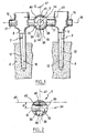
- a first mode of the osteosynthesis system according to the invention for a spine makes it possible to constitute the osteosynthesis device shown.
- the system has only first and second organs anchor or pedicle screws 2 adapted to be fixed respectively to two adjacent vertebrae 4 one of the other from a patient's spine.
- the system further includes a connecting member 6 adapted to connect these two anchoring members 2 between them.
- Each of the two anchoring members 2 comprises a elongated body 8 with longitudinal axis 10 having a foot threaded 12 of slightly conical shape with axis 10 se narrowing towards the free end of the foot, suitable for be anchored in the associated vertebra 4.
- the body 10 has a head opposite longitudinally at the end free from foot 12 and intended to extend outside of vertebra 4 in the patient's body.
- the connecting member 6 is here in one piece. It has a first and a second portion of attachment 16 each comprising a cylindrical rod rectilinear 17.
- the two rods 17 are aligned one with the other and have a common longitudinal axis 18 which is the longitudinal axis of the connecting member and the axis alignment of the two rods 17.
- Each fixing portion 16 is adapted to be rigidly fixed to the head of one of the anchoring members according to known means.
- Axis 18 of the liaison body is then substantially perpendicular to the axis 10 of the anchoring organ.
- each anchor member 2 is anchored in the associated vertebra 4, then we fix the organs anchoring 2 rigidly to the connecting member 6.
- the connecting member 6 further comprises a joining part 28 contiguous to the two portions of attachment 16, by one end of each rod 17 and extending in the longitudinal axis 18 between the two rods.
- the junction part 28 has an external face 30 generally spherical in shape, having a center of curvature on the longitudinal axis 18, halfway of the two end portions 16.
- the joining part 28 has a recess cylindrical 32 passing right through it following a diameter of the sphere.
- the cylindrical recess 32 has a cylinder axis 34 intercepting the longitudinal axis 18 of the connecting member halfway between the two portions end 16 and extending perpendicular to this longitudinal axis 18.
- the joining part 28 also has a indentation 36 in the shape of a spbèxe quarter, delimited by two flat faces 38 of the joining part lying opposite each other and passing each by the axis 34 of the cylindrical recess.
- Notch 36 extends in a radial direction, to the axis of cylinder 34, from the spherical outer face 30 to the cylindrical recess 32.
- the angle a of this notch, defined around the axis 34 of the recess cylindrical by the two flat faces 38, is approximately 15 °.
- One of the planar faces 38 is perpendicular to the longitudinal axis 18 so that the notch extends on one side of the median plane transverse to axis 18 of the liaison body.
- the cylindrical recess 34 and the notch 36 allow to distinguish two portions of the part of junction 28 extending on either side of the axis longitudinal and alignment 18. So the part of junction has two stops 39 extending from a first side of the longitudinal axis 18 associated with the notch 36. Each stop 39 extends from one of the portions of respective fixing 16 to notch 36, the opposite faces 38 constituting two end faces of the stops.
- the joining part 28 also includes a intermediate portion 40 extending from a second side of the longitudinal axis 18 opposite the notch 36.
- the two stops 39 extend by the same side of the intermediate portion 40 that the axis longitudinal 18. This axis 18 extends between the portion intermediate 40 on the one hand and the two stops 39 on the other go.
- the spherical face 30 constitutes an external face stops 39 and intermediate portion 40.
- the spherical faces of the intermediate portion and stops have the same center of curvature.
- the recess cylindrical 32 defines a cylindrical internal face of stops 38 and the intermediate portion 40.
- the intermediate portion 40 is offset laterally with respect to the longitudinal axis 18 which is the alignment axis of the two fixing portions 16.
- the intermediate portion 40 has a neutral fiber 42.
- the offset presents a measure "d" taken between the fiber neutral 42 and the longitudinal axis 18 and extending perpendicular to this axis. This measurement here is equal about the diameter of the stems 17 portions end 16.
- the two end portions 16 are connected to each other only through the intermediate portion 40. This exerts constraints opposing the approximation and distance in following translation the longitudinal axis 18 of the two fastening portions 16 from each other, and therefore from the two anchoring members 2 one of the other.
- the intermediate portion 40 is elastically deformable around a first axis of deformation 45 parallel to the axis 34 of the recess 32 and crossing the intermediate portion at the fiber neutral 42.
- the connecting member 6 During the installation of the system, we orient the connecting member 6 around its longitudinal axis 18 so that the stops 39 are on the side of the vertebrae 4, the intermediate portion 40 being located side opposite to the vertebrae 4. So the first axis of deformation 45 extends perpendicular to the axis longitudinal 10 of the anchoring members 2 and the second deformation axis 47 is substantially parallel to the axes 10.
- the intermediate portion 40 is adapted to bend along each of the three deformation axes for absorb at least some of the stresses normally on the disc between the two vertebrae 4. This bending takes place according to one or more of these axes at once.
- the two stops 39 bear one against the other when the intermediate portion 40 is bent around the first deformation axis 45, at an angle a equal to a predetermined limit value, linked to the shape of the body 28, in the direction of rotation corresponding to a bringing the two stops together. We thus prohibits deformation of the connecting member on an angle greater than the predetermined value.
- This system performs a flexible arthrodesis between the two vertebrae.
- Figures 3 and 4 show a second mode of the osteosynthesis system according to the invention in which the different elements bear references increased by a hundred.
- the system also includes this time a third anchoring member, not shown, and extending to the right of the device visible in Figure 3.
- the three anchors are each identical to those of the first mode.
- the connecting member 106 comprises a part junction 128 this time comprising a first element link 106a and a second link element 106b separate from each other.
- the second connecting element 106b comprises a rigid elongated straight rod 144 with longitudinal axis 18 and circular section. Attachment to the second element 106b of the second and third organs anchoring is done in the same way as in the first fashion.
- the second connecting element 106b comprises in particular the second fixing portion 16.
- the first connecting element 106a comprises a first fixing portion 16 identical to the first fixing portion of the first mode. It comprises also, adjacent to one end of the portion of attachment, an intermediate portion 40 and two stops 39.
- the first connecting element 106a further comprises a cylindrical sleeve 146 having an external face cylindrical 148 of the same radius as the radius of curvature of the spherical face 30 and a cylindrical internal face 150.
- the fixing portion 16 and the sleeve 146 have as their axis the longitudinal axis 18 of the connecting member.
- the face external 148 extends in continuation and continuity from the spherical face 30 to the opposite end longitudinally to the fixing portion 16.
- the external face of one of the stops 39 and part of the external face of the intermediate portion 40 have a shape cylindrical.
- the internal face 150 of the sleeve 146 has a radius slightly greater than the radius of the rod 144 of the second element 106b. This internal face 150 defines a housing adapted to receive this rod.
- the wall of the sleeve 146 is crossed by a cylindrical duct with axis 151 perpendicular to the axis longitudinal 18 of the sleeve and opening onto the faces external 148 and internal 150 of the sleeve.
- This duct 151 is threaded, the second connecting element 106b comprising a screw 152 adapted to be screwed into this conduit to come into abutment against rod 144 received in the housing 150 in order to lock the rod in the housing in several positions to choose along the longitudinal axis 18.
- Rod 144, housing 150 and screw 152 thus constitute means for fixing the two connecting elements 106a and 106b to each other, to adjust the distance between the two portions attachment 16 along the longitudinal axis 18.
- the rod 144 of the second element is engaged 106b in the housing 150 of the first connecting element 106a without tightening the screw 152 so that the rod 144 remains free to slide in the housing along the axis longitudinal 18.
- the connecting member 106 is put in place and each of the three anchoring members is fixed to the member 106.
- the rod 144 constitutes a part of the link 106 adapted to rigidly connect the third anchor to the second anchor.
- the three anchoring members are interconnected by the link 106.
- the different parts of the osteosynthesis system will for example be made of a biocompatible alloy.
- the column patient's backbone will have two systems of osteosynthesis arranged symmetrically on the side and across a median longitudinal plane of the column in being attached to the same vertebrae.
- the maximum amplitude of the flexions will be typically 2 ° around the third axis of deformation 49 (torsion) and from 5 to 6 ° around the second axis of deformation 47 (lateral flexion).
- link member 6 of the first embodiment fixed length
- organ link 106 of the second embodiment variable length
- This system may include more than three organs anchor.
- the same liaison body may in particular have one or more joining parts 28 (of a single piece) and / or one or more joining parts 128 into two separate parts, each joining part being intended to extend between two anchoring members.
- the link member will include a joining part 28 in one piece at one end, followed by several 128 to two junction parts elements.
- the center of curvature of the spherical face of the intermediate portion and / or the center of curvature of the spherical face of the stops may be located elsewhere than on the axis 34 of the cylindrical recess 32.
- a system osteosynthesis for spine comprising at less of the first, second and third organs anchors adapted to be fixed to first, second and third respective vertebrae of the column vertebral, and a connecting organ (in one or more parts) adapted to rigidly connect the second and third anchors, and adapted to connecting the first and second organs to each other anchor-by exerting constraints against the bringing together the first and second anchor members in translation towards each other and being deformable elastically in flexion around at least one axis of deformation between the first and second organs anchor.
- the bond is subjected to a bending moment and bends elastically around the axis of deformation. He collects therefore partially these constraints.
- the system recreates partially the biomechanics of the functional unit composed of the first and second fixed vertebrae, as well that of the intervertebral disc and thus makes it possible to attenuate the transfer of the constraints on the disc overlying the fixation.
- Such an osteosynthesis system avoids, when the system concerns at least three vertebrae connected between them, the appearance of a sudden discontinuity in the stress distribution between the last vertebra of the rigid series and the first free vertebra, and on the contrary, promotes a harmonious distribution of constraints along the column.
Landscapes
- Health & Medical Sciences (AREA)
- Orthopedic Medicine & Surgery (AREA)
- Life Sciences & Earth Sciences (AREA)
- Neurology (AREA)
- Surgery (AREA)
- Heart & Thoracic Surgery (AREA)
- Engineering & Computer Science (AREA)
- Biomedical Technology (AREA)
- Nuclear Medicine, Radiotherapy & Molecular Imaging (AREA)
- Medical Informatics (AREA)
- Molecular Biology (AREA)
- Animal Behavior & Ethology (AREA)
- General Health & Medical Sciences (AREA)
- Public Health (AREA)
- Veterinary Medicine (AREA)
- Prostheses (AREA)
- Surgical Instruments (AREA)
- Media Introduction/Drainage Providing Device (AREA)
Claims (13)
- Osteosynthesesystem für die Wirbelsäule, mit mindestens zwei Verankerungsorganen (2), die dazu eingerichtet sind, an zwei Wirbeln (4) der Wirbelsäule befestigt zu werden, und einem Verbindungsorgan (6; 106), das dazu eingerichtet ist, die beiden Verankerungsorgane zu verbinden, indem es Kräfte gegen die Annäherung der beiden Verankerungsorgane bei der Translation zueinander ausübt, wobei das Verbindungsorgan (6; 106) elastisch um mindestens eine Verformungsachse (45, 47, 49) biegeverformbar ist, wobei das Verbindungsorgan (6; 106) mindestens zwei Befestigungsabschnitte (16), die dazu eingerichtet sind, an den beiden Verankerungsorganen (2) befestigt zu werden, und mindestens einen Zwischenabschnitt (40) aufweist, so daß die beiden Befestigungsabschnitte alleine über den Zwischenabschnitt verbunden sind, und wobei der Zwischenabschnitt bezüglich einer Ausrichtachse (18), die durch die beiden Befestigungsabschnitte (16) definiert ist, versetzt ist, dadurch gekennzeichnet, daß, für den oder jeden Zwischenabschnitt (40), das Verbindungsorgan (6; 106) außerdem zwei Anschläge (39) aufweist, die sich einander gegenüberliegend erstrecken und derart angeordnet sind, daß sie in gegenseitige Anlage gelangen, wenn das Verbindungsorgan rund um die Verformungsachse oder mindestens die eine (45) der Verformungsachsen in einer gegebenen Drehrichtung um einen Winkel (a) verformt ist, der einem bestimmten Grenzwert entspricht.
- System nach Anspruch 1, dadurch gekennzeichnet, daß die Verformungsachse oder mindestens die eine (45) der Verformungsachsen sich senkrecht zu einer Längsrichtung (10) eines jeden Verankerungsorganes (2) und zu einer Längsrichtung (18) des Verbindungsorganes (6; 106) erstreckt.
- System nach Anspruch 1 oder 2, dadurch gekennzeichnet, daß die Verformungsachse oder mindestens die eine (47) der Verformungsachsen sich im wesentlichen parallel zu einer Längsrichtung (10) eines jeden Verankerungsorganes (2) erstreckt.
- System nach irgendeinem der Ansprüche 1 bis 3, dadurch gekennzeichnet, daß die Verformungsachse oder mindestens die eine (49) der Verformungsachsen sich parallel zu einer Längsrichtung (18) des Verbindungsorganes (6; 106) erstreckt.
- System nach irgendeinem der Ansprüche 1 bis 4, dadurch gekennzeichnet, daß die Ausrichtachse (18) sich zwischen einerseits dem Zwischenabschnitt (40) und andererseits den beiden Anschlägen (39) erstreckt.
- System nach irgendeinem der Ansprüche 1 bis 5, dadurch gekennzeichnet, daß der Zwischenabschnitt (40) eine Außenfläche (30) mit kugeliger Form aufweist.
- System nach irgendeinem der Ansprüche 1 bis 6, dadurch gekennzeichnet, daß die beiden Anschläge (39) jeweils eine Außenfläche (30) mit kugeliger Form aufweisen.
- System nach den Ansprüchen 6 und 7, dadurch gekennzeichnet, daß die kugelige Fläche (30) des Zwischenabschnitts und die kugelige Fläche (30) der beiden Anschläge ein und dieselbe-Krümmungsmitte aufweisen.
- System nach irgendeinem der Ansprüche 1 bis 8, dadurch gekennzeichnet, daß für das oder für jedes Paar von Befestigungsabschnitten (16) das Verbindungsorgan (16) einen Zusammenfügungsabschnitt (28) aufweist, der an die beiden Befestigungsabschnitte angrenzt, wobei der Zusammenfügungsabschnitt, der dem Paar oder mindestens einem der Paare von Befestigungsabschnitten zugeordnet ist, einstückig ist.
- System nach irgendeinem der Ansprüche 1 bis 9, dadurch gekennzeichnet, daß für das oder für jedes Paar von Betestigungsabschnitten (16) das Verbindungsorgan (106) einen Zusammenfügungsabschnitt (128) aufweist, der an die beiden Befestigungsabschnitte angrenzt, wobei der Zusammenfügungsabschnitt, der dem Paar oder mindestens einem der Paare von Befestigungsabschnitten zugeordnet ist, ein erstes und ein zweites Verbindungselement (106a, 106b), die voneinander unterschieden sind, sowie Mittel zur Befestigung des ersten und zweiten Verbindungselements aneinander aufweist.
- System nach Anspruch 10, dadurch gekennzeichnet, daß diese Befestigungsmittel dazu eingerichtet sind, die Einregulierung des Abstandes zwischen den beiden, zugeordneten Verankerungsorganen (2) entsprechend der Längsrichtung (18) des Verbindungsorganes (106) zu gestatten.
- System nach Anspruch 11, dadurch gekennzeichnet, daß das zweite Verbindungselement (106b) eine Stange (144) aufweist und das erste Verbindungselement (106a) einen Sitz (150) darbietet, der zur Aufnahme der Stange eingerichtet ist, wobei das erste Verbindungselement (106b) Blockierungsmittel (152) für die Stange im Inneren des Sitzes (150) in mehreren Lagen entsprechend der Längsrichtung (18) des Verbindungsorganes aufweist.
- System nach irgendeinem der Ansprüche 1 bis 12, dadurch gekennzeichnet, daß die Ausrichtachse (18) sich zwischen dem Zwischenabschnitt (40) und den Wirbeln (4) erstreckt.
Applications Claiming Priority (3)
| Application Number | Priority Date | Filing Date | Title |
|---|---|---|---|
| FR9613956 | 1996-11-15 | ||
| FR9613956A FR2755844B1 (fr) | 1996-11-15 | 1996-11-15 | Systeme d'osteosynthese a deformation elastique pour colonne vertebrale |
| PCT/FR1997/002037 WO1998022033A1 (fr) | 1996-11-15 | 1997-11-13 | Systeme d'osteosynthese a deformation elastique pour colonne vertebrale |
Publications (2)
| Publication Number | Publication Date |
|---|---|
| EP0951246A1 EP0951246A1 (de) | 1999-10-27 |
| EP0951246B1 true EP0951246B1 (de) | 2003-05-07 |
Family
ID=9497659
Family Applications (1)
| Application Number | Title | Priority Date | Filing Date |
|---|---|---|---|
| EP97945916A Expired - Lifetime EP0951246B1 (de) | 1996-11-15 | 1997-11-13 | Elastisch verformbares osteosynthesesystem für die wirbelsäule |
Country Status (11)
| Country | Link |
|---|---|
| US (1) | US6267764B1 (de) |
| EP (1) | EP0951246B1 (de) |
| JP (1) | JP2001507957A (de) |
| KR (1) | KR100442555B1 (de) |
| AT (1) | ATE239426T1 (de) |
| AU (1) | AU727605B2 (de) |
| CA (1) | CA2272140C (de) |
| DE (2) | DE69721822T2 (de) |
| ES (1) | ES2149735T3 (de) |
| FR (1) | FR2755844B1 (de) |
| WO (1) | WO1998022033A1 (de) |
Cited By (15)
| Publication number | Priority date | Publication date | Assignee | Title |
|---|---|---|---|---|
| US7722651B2 (en) | 2005-10-21 | 2010-05-25 | Depuy Spine, Inc. | Adjustable bone screw assembly |
| US7935134B2 (en) | 2004-10-20 | 2011-05-03 | Exactech, Inc. | Systems and methods for stabilization of bone structures |
| US7951172B2 (en) | 2005-03-04 | 2011-05-31 | Depuy Spine Sarl | Constrained motion bone screw assembly |
| US7951175B2 (en) | 2005-03-04 | 2011-05-31 | Depuy Spine, Inc. | Instruments and methods for manipulating a vertebra |
| US7998175B2 (en) | 2004-10-20 | 2011-08-16 | The Board Of Trustees Of The Leland Stanford Junior University | Systems and methods for posterior dynamic stabilization of the spine |
| US8025680B2 (en) | 2004-10-20 | 2011-09-27 | Exactech, Inc. | Systems and methods for posterior dynamic stabilization of the spine |
| US8096996B2 (en) | 2007-03-20 | 2012-01-17 | Exactech, Inc. | Rod reducer |
| US8226690B2 (en) | 2005-07-22 | 2012-07-24 | The Board Of Trustees Of The Leland Stanford Junior University | Systems and methods for stabilization of bone structures |
| US8348952B2 (en) | 2006-01-26 | 2013-01-08 | Depuy International Ltd. | System and method for cooling a spinal correction device comprising a shape memory material for corrective spinal surgery |
| US8523865B2 (en) | 2005-07-22 | 2013-09-03 | Exactech, Inc. | Tissue splitter |
| US8551142B2 (en) | 2004-10-20 | 2013-10-08 | Exactech, Inc. | Methods for stabilization of bone structures |
| US8608746B2 (en) | 2008-03-10 | 2013-12-17 | DePuy Synthes Products, LLC | Derotation instrument with reduction functionality |
| US8709015B2 (en) | 2008-03-10 | 2014-04-29 | DePuy Synthes Products, LLC | Bilateral vertebral body derotation system |
| US9101416B2 (en) | 2003-01-24 | 2015-08-11 | DePuy Synthes Products, Inc. | Spinal rod approximator |
| US10973556B2 (en) | 2008-06-17 | 2021-04-13 | DePuy Synthes Products, Inc. | Adjustable implant assembly |
Families Citing this family (256)
| Publication number | Priority date | Publication date | Assignee | Title |
|---|---|---|---|---|
| FR2778085B1 (fr) * | 1998-04-30 | 2001-01-05 | Fred Zacouto | Implant squelettique |
| FR2897259B1 (fr) | 2006-02-15 | 2008-05-09 | Ldr Medical Soc Par Actions Si | Cage intersomatique transforaminale a greffon de fusion intervetebrale et instrument d'implantation de la cage |
| FR2799949B1 (fr) | 1999-10-22 | 2002-06-28 | Abder Benazza | Dispositif d'ostheosynthese rachidienne |
| AU767854B2 (en) * | 1999-12-20 | 2003-11-27 | Synthes Gmbh | Device for the stabilisation of two adjacent verterbral bodies of the spine |
| DE10004712C1 (de) * | 2000-02-03 | 2001-08-09 | Aesculap Ag & Co Kg | Knochenplatte |
| US20020133155A1 (en) * | 2000-02-25 | 2002-09-19 | Ferree Bret A. | Cross-coupled vertebral stabilizers incorporating spinal motion restriction |
| US6402750B1 (en) * | 2000-04-04 | 2002-06-11 | Spinlabs, Llc | Devices and methods for the treatment of spinal disorders |
| JP2004516040A (ja) | 2000-06-30 | 2004-06-03 | リトラン、スティーブン | 多軸継手装置及び方法 |
| FR2812186B1 (fr) * | 2000-07-25 | 2003-02-28 | Spine Next Sa | Piece de liaison souple pour la stabilisation du rachis |
| FR2812185B1 (fr) | 2000-07-25 | 2003-02-28 | Spine Next Sa | Piece de liaison semi-rigide pour la stabilisation du rachis |
| US7833250B2 (en) | 2004-11-10 | 2010-11-16 | Jackson Roger P | Polyaxial bone screw with helically wound capture connection |
| ATE296580T1 (de) | 2000-09-18 | 2005-06-15 | Zimmer Gmbh | Pedikelschraube für intervertebrale stützelemente |
| US6692434B2 (en) | 2000-09-29 | 2004-02-17 | Stephen Ritland | Method and device for retractor for microsurgical intermuscular lumbar arthrodesis |
| US7166073B2 (en) | 2000-09-29 | 2007-01-23 | Stephen Ritland | Method and device for microsurgical intermuscular spinal surgery |
| FR2814936B1 (fr) * | 2000-10-11 | 2003-02-07 | Frederic Fortin | Dispositif de liaison vertebrale souple et monobloc fonctionnant de maniere multidirectionnelle |
| US20050080486A1 (en) | 2000-11-29 | 2005-04-14 | Fallin T. Wade | Facet joint replacement |
| US6579319B2 (en) | 2000-11-29 | 2003-06-17 | Medicinelodge, Inc. | Facet joint replacement |
| US6419703B1 (en) | 2001-03-01 | 2002-07-16 | T. Wade Fallin | Prosthesis for the replacement of a posterior element of a vertebra |
| US6565605B2 (en) | 2000-12-13 | 2003-05-20 | Medicinelodge, Inc. | Multiple facet joint replacement |
| FR2819169A1 (fr) | 2001-01-09 | 2002-07-12 | Brice Edouard | Dispositif d'osteosynthese pour colonne vertebrale |
| US7090698B2 (en) | 2001-03-02 | 2006-08-15 | Facet Solutions | Method and apparatus for spine joint replacement |
| US6802844B2 (en) * | 2001-03-26 | 2004-10-12 | Nuvasive, Inc | Spinal alignment apparatus and methods |
| US8353932B2 (en) | 2005-09-30 | 2013-01-15 | Jackson Roger P | Polyaxial bone anchor assembly with one-piece closure, pressure insert and plastic elongate member |
| US10729469B2 (en) | 2006-01-09 | 2020-08-04 | Roger P. Jackson | Flexible spinal stabilization assembly with spacer having off-axis core member |
| US8292926B2 (en) | 2005-09-30 | 2012-10-23 | Jackson Roger P | Dynamic stabilization connecting member with elastic core and outer sleeve |
| US7862587B2 (en) | 2004-02-27 | 2011-01-04 | Jackson Roger P | Dynamic stabilization assemblies, tool set and method |
| US10258382B2 (en) | 2007-01-18 | 2019-04-16 | Roger P. Jackson | Rod-cord dynamic connection assemblies with slidable bone anchor attachment members along the cord |
| GB0114783D0 (en) * | 2001-06-16 | 2001-08-08 | Sengupta Dilip K | A assembly for the stabilisation of vertebral bodies of the spine |
| FR2827156B1 (fr) | 2001-07-13 | 2003-11-14 | Ldr Medical | Dispositif de cage vertebrale avec fixation modulaire |
| FR2827498B1 (fr) | 2001-07-18 | 2004-05-14 | Frederic Fortin | Dispositif de liaison vertebrale souple constitue d'elements palliant une deficience du rachis |
| FR2828643B1 (fr) * | 2001-08-17 | 2004-12-24 | Hassan Razian | Plaque d'osteosynthese notamment rachidienne |
| AU2002327801B2 (en) | 2001-09-28 | 2008-03-06 | Stephen Ritland | Connection rod for screw or hook polyaxial system and method of use |
| US6991632B2 (en) | 2001-09-28 | 2006-01-31 | Stephen Ritland | Adjustable rod and connector device and method of use |
| US7261713B2 (en) * | 2001-10-09 | 2007-08-28 | Synthes (Usa) | Adjustable fixator |
| ES2293963T3 (es) * | 2001-12-07 | 2008-04-01 | Synthes Gmbh | Elemento amortiguador para la columna vertebral. |
| US6572653B1 (en) | 2001-12-07 | 2003-06-03 | Rush E. Simonson | Vertebral implant adapted for posterior insertion |
| US7763047B2 (en) | 2002-02-20 | 2010-07-27 | Stephen Ritland | Pedicle screw connector apparatus and method |
| US6966910B2 (en) | 2002-04-05 | 2005-11-22 | Stephen Ritland | Dynamic fixation device and method of use |
| EP2457528A1 (de) | 2002-05-08 | 2012-05-30 | Stephen Ritland | Dynamische Befestigungsvorrichtung und Verwendungsverfahren dafür |
| DE10236691B4 (de) * | 2002-08-09 | 2005-12-01 | Biedermann Motech Gmbh | Dynamische Stabilisierungseinrichtung für Knochen, insbesondere für Wirbel |
| FR2843538B1 (fr) | 2002-08-13 | 2005-08-12 | Frederic Fortin | Dispositif de distraction et d'amortissement ajustable a la croissance du rachis |
| WO2004017817A2 (en) * | 2002-08-23 | 2004-03-04 | Mcafee Paul C | Metal-backed uhmpe rod sleeve system preserving spinal motion |
| US8876868B2 (en) | 2002-09-06 | 2014-11-04 | Roger P. Jackson | Helical guide and advancement flange with radially loaded lip |
| WO2006052796A2 (en) | 2004-11-10 | 2006-05-18 | Jackson Roger P | Helical guide and advancement flange with break-off extensions |
| FR2845587B1 (fr) * | 2002-10-14 | 2005-01-21 | Scient X | Dispositif dynamique de liaison intervertebrale a debattement controle multidirectionnel |
| FR2846223B1 (fr) * | 2002-10-24 | 2006-04-14 | Frederic Fortin | Dispositif de liaison intervertebrale souple et modulaire comportant un element permettant de travailler de maniere multidirectionnelle |
| FR2846222B1 (fr) * | 2002-10-24 | 2005-08-26 | Frederic Fortin | Dispositif de liaison vertebrale souple modulaire et ajustable |
| US8540753B2 (en) | 2003-04-09 | 2013-09-24 | Roger P. Jackson | Polyaxial bone screw with uploaded threaded shank and method of assembly and use |
| US7621918B2 (en) | 2004-11-23 | 2009-11-24 | Jackson Roger P | Spinal fixation tool set and method |
| US7713287B2 (en) * | 2003-05-02 | 2010-05-11 | Applied Spine Technologies, Inc. | Dynamic spine stabilizer |
| US8652175B2 (en) * | 2003-05-02 | 2014-02-18 | Rachiotek, Llc | Surgical implant devices and systems including a sheath member |
| KR100859827B1 (ko) | 2003-05-02 | 2008-09-23 | 예일 유니버시티 | 동적 척추 안정장치 |
| US8262571B2 (en) | 2003-05-22 | 2012-09-11 | Stephen Ritland | Intermuscular guide for retractor insertion and method of use |
| US7377923B2 (en) | 2003-05-22 | 2008-05-27 | Alphatec Spine, Inc. | Variable angle spinal screw assembly |
| US6986771B2 (en) * | 2003-05-23 | 2006-01-17 | Globus Medical, Inc. | Spine stabilization system |
| US8366753B2 (en) | 2003-06-18 | 2013-02-05 | Jackson Roger P | Polyaxial bone screw assembly with fixed retaining structure |
| US7766915B2 (en) | 2004-02-27 | 2010-08-03 | Jackson Roger P | Dynamic fixation assemblies with inner core and outer coil-like member |
| US7967850B2 (en) | 2003-06-18 | 2011-06-28 | Jackson Roger P | Polyaxial bone anchor with helical capture connection, insert and dual locking assembly |
| US8092500B2 (en) | 2007-05-01 | 2012-01-10 | Jackson Roger P | Dynamic stabilization connecting member with floating core, compression spacer and over-mold |
| US7776067B2 (en) | 2005-05-27 | 2010-08-17 | Jackson Roger P | Polyaxial bone screw with shank articulation pressure insert and method |
| US8936623B2 (en) | 2003-06-18 | 2015-01-20 | Roger P. Jackson | Polyaxial bone screw assembly |
| US8979900B2 (en) | 2003-09-24 | 2015-03-17 | DePuy Synthes Products, LLC | Spinal stabilization device |
| US20050203513A1 (en) * | 2003-09-24 | 2005-09-15 | Tae-Ahn Jahng | Spinal stabilization device |
| US7815665B2 (en) * | 2003-09-24 | 2010-10-19 | N Spine, Inc. | Adjustable spinal stabilization system |
| US20050065516A1 (en) * | 2003-09-24 | 2005-03-24 | Tae-Ahn Jahng | Method and apparatus for flexible fixation of a spine |
| US7763052B2 (en) * | 2003-12-05 | 2010-07-27 | N Spine, Inc. | Method and apparatus for flexible fixation of a spine |
| CA2540591C (en) * | 2003-09-29 | 2011-06-28 | Synthes Gmbh | Device for the elastic stabilisation of bodies of the vertebra |
| AU2003264226A1 (en) * | 2003-09-29 | 2005-04-14 | Synthes Gmbh | Dynamic damping element for two bones |
| US20050090822A1 (en) * | 2003-10-24 | 2005-04-28 | Dipoto Gene | Methods and apparatus for stabilizing the spine through an access device |
| DE502004011567D1 (de) * | 2003-11-07 | 2010-09-30 | Biedermann Motech Gmbh | Stabilisierungseinrichtung mit einem Knochenverankerungselement |
| US8632570B2 (en) | 2003-11-07 | 2014-01-21 | Biedermann Technologies Gmbh & Co. Kg | Stabilization device for bones comprising a spring element and manufacturing method for said spring element |
| US8926700B2 (en) | 2003-12-10 | 2015-01-06 | Gmedelware 2 LLC | Spinal facet joint implant |
| US7553320B2 (en) * | 2003-12-10 | 2009-06-30 | Warsaw Orthopedic, Inc. | Method and apparatus for replacing the function of facet joints |
| US7527638B2 (en) | 2003-12-16 | 2009-05-05 | Depuy Spine, Inc. | Methods and devices for minimally invasive spinal fixation element placement |
| US11419642B2 (en) | 2003-12-16 | 2022-08-23 | Medos International Sarl | Percutaneous access devices and bone anchor assemblies |
| US7179261B2 (en) | 2003-12-16 | 2007-02-20 | Depuy Spine, Inc. | Percutaneous access devices and bone anchor assemblies |
| US7597694B2 (en) * | 2004-01-30 | 2009-10-06 | Warsaw Orthopedic, Inc. | Instruments and methods for minimally invasive spinal stabilization |
| US7815664B2 (en) * | 2005-01-04 | 2010-10-19 | Warsaw Orthopedic, Inc. | Systems and methods for spinal stabilization with flexible elements |
| US8029548B2 (en) * | 2008-05-05 | 2011-10-04 | Warsaw Orthopedic, Inc. | Flexible spinal stabilization element and system |
| PT1711133E (pt) | 2004-02-04 | 2011-06-01 | Ldr Medical | Prótese de disco intervertebral |
| US7993373B2 (en) | 2005-02-22 | 2011-08-09 | Hoy Robert W | Polyaxial orthopedic fastening apparatus |
| US8353933B2 (en) | 2007-04-17 | 2013-01-15 | Gmedelaware 2 Llc | Facet joint replacement |
| US8562649B2 (en) | 2004-02-17 | 2013-10-22 | Gmedelaware 2 Llc | System and method for multiple level facet joint arthroplasty and fusion |
| JP2007525274A (ja) | 2004-02-27 | 2007-09-06 | ロジャー・ピー・ジャクソン | 整形外科インプラントロッド整復器具セット及び方法 |
| US8152810B2 (en) | 2004-11-23 | 2012-04-10 | Jackson Roger P | Spinal fixation tool set and method |
| US7160300B2 (en) | 2004-02-27 | 2007-01-09 | Jackson Roger P | Orthopedic implant rod reduction tool set and method |
| DE102004011685A1 (de) * | 2004-03-09 | 2005-09-29 | Biedermann Motech Gmbh | Stabförmiges Element für die Anwendung in der Wirbelsäulen- oder Unfallchirurgie und Stabilisierungseinrichtung mit einem solchen stabförmigen Element |
| US7645294B2 (en) | 2004-03-31 | 2010-01-12 | Depuy Spine, Inc. | Head-to-head connector spinal fixation system |
| US7717939B2 (en) | 2004-03-31 | 2010-05-18 | Depuy Spine, Inc. | Rod attachment for head to head cross connector |
| EP1740111B1 (de) * | 2004-04-28 | 2009-08-05 | Synthes GmbH | Vorrichtung zur dynamischen stabilisierung von knochen |
| FR2869524B1 (fr) * | 2004-04-28 | 2006-06-23 | Frederic Fortin | Dispositif intervertebral suppleant a une deficience d'amortissement et de stabilisation du rachis |
| US7819900B2 (en) * | 2004-05-27 | 2010-10-26 | Depuy Spine, Inc. | Tri-joint implant methods |
| US7507242B2 (en) | 2004-06-02 | 2009-03-24 | Facet Solutions | Surgical measurement and resection framework |
| US8764801B2 (en) | 2005-03-28 | 2014-07-01 | Gmedelaware 2 Llc | Facet joint implant crosslinking apparatus and method |
| US7758581B2 (en) | 2005-03-28 | 2010-07-20 | Facet Solutions, Inc. | Polyaxial reaming apparatus and method |
| US8858599B2 (en) * | 2004-06-09 | 2014-10-14 | Warsaw Orthopedic, Inc. | Systems and methods for flexible spinal stabilization |
| US20060015100A1 (en) | 2004-06-23 | 2006-01-19 | Panjabi Manohar M | Spinal stabilization devices coupled by torsional member |
| US7261738B2 (en) | 2004-06-30 | 2007-08-28 | Depuy Spine, Inc. | C-shaped disc prosthesis |
| US7351261B2 (en) * | 2004-06-30 | 2008-04-01 | Depuy Spine, Inc. | Multi-joint implant |
| US8021428B2 (en) * | 2004-06-30 | 2011-09-20 | Depuy Spine, Inc. | Ceramic disc prosthesis |
| US7854752B2 (en) | 2004-08-09 | 2010-12-21 | Theken Spine, Llc | System and method for dynamic skeletal stabilization |
| AU2005274013A1 (en) * | 2004-08-09 | 2006-02-23 | Innovative Spinal Technologies | System and method for dynamic skeletal stabilization |
| US7717938B2 (en) | 2004-08-27 | 2010-05-18 | Depuy Spine, Inc. | Dual rod cross connectors and inserter tools |
| US7887566B2 (en) * | 2004-09-16 | 2011-02-15 | Hynes Richard A | Intervertebral support device with bias adjustment and related methods |
| US7455639B2 (en) | 2004-09-20 | 2008-11-25 | Stephen Ritland | Opposing parallel bladed retractor and method of use |
| US7651502B2 (en) | 2004-09-24 | 2010-01-26 | Jackson Roger P | Spinal fixation tool set and method for rod reduction and fastener insertion |
| US7766940B2 (en) * | 2004-12-30 | 2010-08-03 | Depuy Spine, Inc. | Posterior stabilization system |
| US8092496B2 (en) * | 2004-09-30 | 2012-01-10 | Depuy Spine, Inc. | Methods and devices for posterior stabilization |
| US20060084976A1 (en) * | 2004-09-30 | 2006-04-20 | Depuy Spine, Inc. | Posterior stabilization systems and methods |
| US7896906B2 (en) * | 2004-12-30 | 2011-03-01 | Depuy Spine, Inc. | Artificial facet joint |
| DE102004048938B4 (de) | 2004-10-07 | 2015-04-02 | Synthes Gmbh | Vorrichtung zur dynamischen Stabilisierung von Rückenwirbelkörpern |
| US20060085076A1 (en) * | 2004-10-15 | 2006-04-20 | Manoj Krishna | Posterior spinal arthroplasty-development of a new posteriorly inserted artificial disc and an artificial facet joint |
| US20090030465A1 (en) * | 2004-10-20 | 2009-01-29 | Moti Altarac | Dynamic rod |
| US20100036423A1 (en) * | 2004-10-20 | 2010-02-11 | Stanley Kyle Hayes | Dynamic rod |
| US20090228045A1 (en) * | 2004-10-20 | 2009-09-10 | Stanley Kyle Hayes | Dynamic rod |
| US20060265074A1 (en) | 2004-10-21 | 2006-11-23 | Manoj Krishna | Posterior spinal arthroplasty-development of a new posteriorly inserted artificial disc, a new anteriorly inserted artifical disc and an artificial facet joint |
| US8926672B2 (en) | 2004-11-10 | 2015-01-06 | Roger P. Jackson | Splay control closure for open bone anchor |
| US9168069B2 (en) | 2009-06-15 | 2015-10-27 | Roger P. Jackson | Polyaxial bone anchor with pop-on shank and winged insert with lower skirt for engaging a friction fit retainer |
| US9980753B2 (en) | 2009-06-15 | 2018-05-29 | Roger P Jackson | pivotal anchor with snap-in-place insert having rotation blocking extensions |
| US8444681B2 (en) | 2009-06-15 | 2013-05-21 | Roger P. Jackson | Polyaxial bone anchor with pop-on shank, friction fit retainer and winged insert |
| US9216041B2 (en) | 2009-06-15 | 2015-12-22 | Roger P. Jackson | Spinal connecting members with tensioned cords and rigid sleeves for engaging compression inserts |
| WO2006057837A1 (en) | 2004-11-23 | 2006-06-01 | Jackson Roger P | Spinal fixation tool attachment structure |
| ATE524121T1 (de) | 2004-11-24 | 2011-09-15 | Abdou Samy | Vorrichtungen zur platzierung eines orthopädischen intervertebralen implantats |
| EP1719468A1 (de) | 2004-12-17 | 2006-11-08 | Zimmer GmbH | Intervertebrales Stabilisierungssystem |
| US7294129B2 (en) * | 2005-02-18 | 2007-11-13 | Ebi, L.P. | Spinal fixation device and associated method |
| US7361196B2 (en) | 2005-02-22 | 2008-04-22 | Stryker Spine | Apparatus and method for dynamic vertebral stabilization |
| US10076361B2 (en) | 2005-02-22 | 2018-09-18 | Roger P. Jackson | Polyaxial bone screw with spherical capture, compression and alignment and retention structures |
| US7901437B2 (en) | 2007-01-26 | 2011-03-08 | Jackson Roger P | Dynamic stabilization member with molded connection |
| US7722647B1 (en) | 2005-03-14 | 2010-05-25 | Facet Solutions, Inc. | Apparatus and method for posterior vertebral stabilization |
| CN103479419B (zh) | 2005-04-08 | 2017-04-12 | 帕拉迪格脊骨有限责任公司 | 棘突间脊椎和腰骶稳定装置及使用方法 |
| US20060264935A1 (en) * | 2005-05-04 | 2006-11-23 | White Patrick M | Orthopedic stabilization device |
| US20060264937A1 (en) * | 2005-05-04 | 2006-11-23 | White Patrick M | Mobile spine stabilization device |
| US7862589B2 (en) * | 2005-05-24 | 2011-01-04 | Lanx, Inc. | Facet replacement |
| US7763051B2 (en) | 2005-06-10 | 2010-07-27 | Depuy Spine, Inc. | Posterior dynamic stabilization systems and methods |
| WO2007012025A2 (en) | 2005-07-19 | 2007-01-25 | Stephen Ritland | Rod extension for extending fusion construct |
| US7811309B2 (en) * | 2005-07-26 | 2010-10-12 | Applied Spine Technologies, Inc. | Dynamic spine stabilization device with travel-limiting functionality |
| US7713288B2 (en) * | 2005-08-03 | 2010-05-11 | Applied Spine Technologies, Inc. | Spring junction and assembly methods for spinal device |
| US7699875B2 (en) * | 2006-04-17 | 2010-04-20 | Applied Spine Technologies, Inc. | Spinal stabilization device with weld cap |
| FR2891135B1 (fr) | 2005-09-23 | 2008-09-12 | Ldr Medical Sarl | Prothese de disque intervertebral |
| US7879074B2 (en) * | 2005-09-27 | 2011-02-01 | Depuy Spine, Inc. | Posterior dynamic stabilization systems and methods |
| WO2007038429A1 (en) | 2005-09-27 | 2007-04-05 | Endius, Inc. | Methods and apparatuses for stabilizing the spine through an access device |
| EP2384711B1 (de) * | 2005-09-27 | 2014-02-26 | Paradigm Spine, LLC. | Interspinöse Wirbelstabilisierungsvorrichtung |
| US7993376B2 (en) * | 2005-09-29 | 2011-08-09 | Depuy Spine, Inc. | Methods of implanting a motion segment repair system |
| US8105368B2 (en) | 2005-09-30 | 2012-01-31 | Jackson Roger P | Dynamic stabilization connecting member with slitted core and outer sleeve |
| US20070093815A1 (en) * | 2005-10-11 | 2007-04-26 | Callahan Ronald Ii | Dynamic spinal stabilizer |
| US20070093814A1 (en) * | 2005-10-11 | 2007-04-26 | Callahan Ronald Ii | Dynamic spinal stabilization systems |
| US20070093813A1 (en) * | 2005-10-11 | 2007-04-26 | Callahan Ronald Ii | Dynamic spinal stabilizer |
| GB0521582D0 (en) | 2005-10-22 | 2005-11-30 | Depuy Int Ltd | An implant for supporting a spinal column |
| US8267970B2 (en) * | 2005-10-25 | 2012-09-18 | Depuy Spine, Inc. | Laminar hook spring |
| US8357181B2 (en) | 2005-10-27 | 2013-01-22 | Warsaw Orthopedic, Inc. | Intervertebral prosthetic device for spinal stabilization and method of implanting same |
| US8109973B2 (en) | 2005-10-31 | 2012-02-07 | Stryker Spine | Method for dynamic vertebral stabilization |
| US8034078B2 (en) | 2008-05-30 | 2011-10-11 | Globus Medical, Inc. | System and method for replacement of spinal motion segment |
| US7704271B2 (en) | 2005-12-19 | 2010-04-27 | Abdou M Samy | Devices and methods for inter-vertebral orthopedic device placement |
| GB0600662D0 (en) | 2006-01-13 | 2006-02-22 | Depuy Int Ltd | Spinal support rod kit |
| US7578849B2 (en) * | 2006-01-27 | 2009-08-25 | Warsaw Orthopedic, Inc. | Intervertebral implants and methods of use |
| US7682376B2 (en) | 2006-01-27 | 2010-03-23 | Warsaw Orthopedic, Inc. | Interspinous devices and methods of use |
| US7815663B2 (en) * | 2006-01-27 | 2010-10-19 | Warsaw Orthopedic, Inc. | Vertebral rods and methods of use |
| US20070233089A1 (en) * | 2006-02-17 | 2007-10-04 | Endius, Inc. | Systems and methods for reducing adjacent level disc disease |
| US20070233068A1 (en) * | 2006-02-22 | 2007-10-04 | Sdgi Holdings, Inc. | Intervertebral prosthetic assembly for spinal stabilization and method of implanting same |
| US8025681B2 (en) | 2006-03-29 | 2011-09-27 | Theken Spine, Llc | Dynamic motion spinal stabilization system |
| WO2007114834A1 (en) * | 2006-04-05 | 2007-10-11 | Dong Myung Jeon | Multi-axial, double locking bone screw assembly |
| WO2007123920A2 (en) * | 2006-04-18 | 2007-11-01 | Joseph Nicholas Logan | Spinal rod system |
| US7942905B2 (en) * | 2006-04-20 | 2011-05-17 | Warsaw Orthopedic, Inc. | Vertebral stabilizer |
| US20070288012A1 (en) * | 2006-04-21 | 2007-12-13 | Dennis Colleran | Dynamic motion spinal stabilization system and device |
| US20070270821A1 (en) * | 2006-04-28 | 2007-11-22 | Sdgi Holdings, Inc. | Vertebral stabilizer |
| US7666211B2 (en) | 2006-12-28 | 2010-02-23 | Mi4Spine, Llc | Vertebral disc annular fibrosis tensioning and lengthening device |
| WO2008003047A2 (en) * | 2006-06-28 | 2008-01-03 | Synthes (U.S.A.) | Dynamic fixation system |
| US7959564B2 (en) | 2006-07-08 | 2011-06-14 | Stephen Ritland | Pedicle seeker and retractor, and methods of use |
| US7806913B2 (en) * | 2006-08-16 | 2010-10-05 | Depuy Spine, Inc. | Modular multi-level spine stabilization system and method |
| US7766942B2 (en) * | 2006-08-31 | 2010-08-03 | Warsaw Orthopedic, Inc. | Polymer rods for spinal applications |
| US8425601B2 (en) * | 2006-09-11 | 2013-04-23 | Warsaw Orthopedic, Inc. | Spinal stabilization devices and methods of use |
| FR2905847B1 (fr) * | 2006-09-14 | 2009-03-27 | Warsaw Orthopedic Inc | Element d'un dispositif de stabilisation du rachis,et dispositif comprenant une paire de tels elements. |
| US8308770B2 (en) * | 2006-09-22 | 2012-11-13 | Depuy Spine, Inc. | Dynamic stabilization system |
| US20090082775A1 (en) * | 2006-10-25 | 2009-03-26 | Moti Altarac | Spondylolisthesis reduction system and method |
| US8361117B2 (en) * | 2006-11-08 | 2013-01-29 | Depuy Spine, Inc. | Spinal cross connectors |
| AR064013A1 (es) * | 2006-11-30 | 2009-03-04 | Paradigm Spine Llc | Sistema de estabilizacion vertebral, interlaminar, interespinoso |
| JP2010512178A (ja) | 2006-12-08 | 2010-04-22 | ロジャー・ピー・ジャクソン | 動的脊椎インプラントのためのツールシステム |
| AU2007333199B2 (en) | 2006-12-10 | 2014-04-17 | Xtant Medical Holdings, Inc. | Posterior functionally dynamic stabilization system |
| FR2910267B1 (fr) * | 2006-12-21 | 2009-01-23 | Ldr Medical Soc Par Actions Si | Dispositif de soutien vertebral |
| US7892265B2 (en) | 2006-12-28 | 2011-02-22 | Mi4Spine, Llc | Surgical screw including a body that facilitates bone in-growth |
| US8029544B2 (en) | 2007-01-02 | 2011-10-04 | Zimmer Spine, Inc. | Spine stiffening device |
| WO2008086467A2 (en) | 2007-01-10 | 2008-07-17 | Facet Solutions, Inc. | Taper-locking fixation system |
| US7875059B2 (en) * | 2007-01-18 | 2011-01-25 | Warsaw Orthopedic, Inc. | Variable stiffness support members |
| US8366745B2 (en) | 2007-05-01 | 2013-02-05 | Jackson Roger P | Dynamic stabilization assembly having pre-compressed spacers with differential displacements |
| US7931676B2 (en) * | 2007-01-18 | 2011-04-26 | Warsaw Orthopedic, Inc. | Vertebral stabilizer |
| US8475498B2 (en) | 2007-01-18 | 2013-07-02 | Roger P. Jackson | Dynamic stabilization connecting member with cord connection |
| WO2008098206A1 (en) * | 2007-02-09 | 2008-08-14 | Altiva Corporation | Dynamic stabilization device |
| US8012177B2 (en) | 2007-02-12 | 2011-09-06 | Jackson Roger P | Dynamic stabilization assembly with frusto-conical connection |
| US8097022B2 (en) * | 2007-02-20 | 2012-01-17 | Warsaw Orthopedic, Inc. | Flexible coupling members for spinal stabilization members |
| US8740944B2 (en) * | 2007-02-28 | 2014-06-03 | Warsaw Orthopedic, Inc. | Vertebral stabilizer |
| US8007519B2 (en) * | 2007-03-13 | 2011-08-30 | Zimmer Spine, Inc. | Dynamic spinal stabilization system and method of using the same |
| US8292929B2 (en) | 2007-03-16 | 2012-10-23 | Zimmer Spine, Inc. | Dynamic spinal stabilization system and method of using the same |
| USD618348S1 (en) * | 2007-03-23 | 2010-06-22 | Disc Motion Technologies, Inc. | Spinal stabilization device |
| USD618349S1 (en) * | 2007-03-23 | 2010-06-22 | Disc Motion Technologies, Inc. | Spinal stabilization device |
| GB0707285D0 (en) * | 2007-04-17 | 2007-05-23 | Burke John | Implantable apparatus for modulation of skeletal growth |
| EP2142121B1 (de) | 2007-04-30 | 2014-04-16 | Globus Medical, Inc. | Flexibles wirbelsäulenstabilisierungssystem |
| US10383660B2 (en) | 2007-05-01 | 2019-08-20 | Roger P. Jackson | Soft stabilization assemblies with pretensioned cords |
| WO2008153747A2 (en) * | 2007-05-25 | 2008-12-18 | Vertiflex, Inc. | Dynamic rod |
| EP2160158A4 (de) | 2007-05-31 | 2013-06-26 | Roger P Jackson | Dynamisches stabilisationsverbindungselement mit vorgespanntem festen kern |
| FR2916956B1 (fr) | 2007-06-08 | 2012-12-14 | Ldr Medical | Cage intersomatique,prothese intervertebrale,dispositif d'ancrage et instrumentation d'implantation |
| CA2693540A1 (en) * | 2007-08-07 | 2009-02-12 | Synthes Usa, Llc | Dynamic cable system |
| US20090088782A1 (en) * | 2007-09-28 | 2009-04-02 | Missoum Moumene | Flexible Spinal Rod With Elastomeric Jacket |
| US8911477B2 (en) | 2007-10-23 | 2014-12-16 | Roger P. Jackson | Dynamic stabilization member with end plate support and cable core extension |
| GB0720762D0 (en) | 2007-10-24 | 2007-12-05 | Depuy Spine Sorl | Assembly for orthopaedic surgery |
| US20090125032A1 (en) * | 2007-11-14 | 2009-05-14 | Gutierrez Robert C | Rod removal instrument |
| US9232968B2 (en) | 2007-12-19 | 2016-01-12 | DePuy Synthes Products, Inc. | Polymeric pedicle rods and methods of manufacturing |
| WO2010147639A1 (en) | 2008-08-01 | 2010-12-23 | Jackson Roger P | Longitudinal connecting member with sleeved tensioned cords |
| US8287571B2 (en) | 2008-08-12 | 2012-10-16 | Blackstone Medical, Inc. | Apparatus for stabilizing vertebral bodies |
| ES2394670T3 (es) * | 2008-10-08 | 2013-02-04 | Biedermann Technologies Gmbh & Co. Kg | Dispositivo de implante alargado y dispositivo de estabilización vertebral |
| US20100114167A1 (en) * | 2008-10-31 | 2010-05-06 | Warsaw Orthopedic, Inc. | Transition rod |
| EP2373236B1 (de) | 2008-12-17 | 2014-05-21 | Synthes GmbH | Dynamischer posteriorer wirbelsäulenstabilisator |
| US8641734B2 (en) | 2009-02-13 | 2014-02-04 | DePuy Synthes Products, LLC | Dual spring posterior dynamic stabilization device with elongation limiting elastomers |
| US8118840B2 (en) | 2009-02-27 | 2012-02-21 | Warsaw Orthopedic, Inc. | Vertebral rod and related method of manufacture |
| US20110040331A1 (en) * | 2009-05-20 | 2011-02-17 | Jose Fernandez | Posterior stabilizer |
| US9668771B2 (en) | 2009-06-15 | 2017-06-06 | Roger P Jackson | Soft stabilization assemblies with off-set connector |
| US11229457B2 (en) | 2009-06-15 | 2022-01-25 | Roger P. Jackson | Pivotal bone anchor assembly with insert tool deployment |
| WO2013043218A1 (en) | 2009-06-15 | 2013-03-28 | Jackson Roger P | Polyaxial bone anchor with pop-on shank and winged insert with friction fit compressive collet |
| EP2753252A1 (de) | 2009-06-15 | 2014-07-16 | Jackson, Roger P. | Polyaxialer knochenanker mit pop-on-schaft und presssitzfixierung mit niedrigprofilkantensperre |
| US8998959B2 (en) | 2009-06-15 | 2015-04-07 | Roger P Jackson | Polyaxial bone anchors with pop-on shank, fully constrained friction fit retainer and lock and release insert |
| US9320543B2 (en) | 2009-06-25 | 2016-04-26 | DePuy Synthes Products, Inc. | Posterior dynamic stabilization device having a mobile anchor |
| US20110166610A1 (en) * | 2009-08-07 | 2011-07-07 | Moti Altarac | Systems and methods for stabilization of bone structures, including thorocolumbar stabilization systems and methods |
| CN102596109B (zh) | 2009-09-17 | 2015-10-21 | Ldr控股公司 | 具有可伸展骨固定部件的椎间植入件 |
| US9011494B2 (en) * | 2009-09-24 | 2015-04-21 | Warsaw Orthopedic, Inc. | Composite vertebral rod system and methods of use |
| AU2010303934B2 (en) | 2009-10-05 | 2014-03-27 | Roger P. Jackson | Polyaxial bone anchor with non-pivotable retainer and pop-on shank, some with friction fit |
| US8764806B2 (en) | 2009-12-07 | 2014-07-01 | Samy Abdou | Devices and methods for minimally invasive spinal stabilization and instrumentation |
| MX2012007642A (es) | 2009-12-31 | 2012-08-01 | Ldr Medical | Dispositivo de anclaje, implante intervertebral e instrumento de implantacion. |
| US9445844B2 (en) | 2010-03-24 | 2016-09-20 | DePuy Synthes Products, Inc. | Composite material posterior dynamic stabilization spring rod |
| US9072546B2 (en) | 2010-08-26 | 2015-07-07 | Warsaw Orthopedic, Inc. | Spinal constructs with improved load-sharing |
| US8979901B2 (en) | 2010-08-26 | 2015-03-17 | Warsaw Orthopedic, Inc. | Dynamic bone fastener with a preset range of motion |
| JP2013540468A (ja) | 2010-09-08 | 2013-11-07 | ロジャー・ピー・ジャクソン | 弾性部および非弾性部を有する動的固定化部材 |
| JP2013545527A (ja) | 2010-11-02 | 2013-12-26 | ロジャー・ピー・ジャクソン | ポップオン式シャンクと枢動可能な保持部とを有する多軸の骨アンカー |
| WO2012128825A1 (en) | 2011-03-24 | 2012-09-27 | Jackson Roger P | Polyaxial bone anchor with compound articulation and pop-on shank |
| US8845728B1 (en) | 2011-09-23 | 2014-09-30 | Samy Abdou | Spinal fixation devices and methods of use |
| US20130103090A1 (en) * | 2011-10-25 | 2013-04-25 | Warsaw Orthopedic, Inc. | Vertebral rod system and methods of use |
| US8911479B2 (en) | 2012-01-10 | 2014-12-16 | Roger P. Jackson | Multi-start closures for open implants |
| US20130226240A1 (en) | 2012-02-22 | 2013-08-29 | Samy Abdou | Spinous process fixation devices and methods of use |
| FR2987256B1 (fr) | 2012-02-24 | 2014-08-08 | Ldr Medical | Dispositif d'ancrage pour implant intervertebral, implant intervertebral et instrumentation d'implantation |
| US9198767B2 (en) | 2012-08-28 | 2015-12-01 | Samy Abdou | Devices and methods for spinal stabilization and instrumentation |
| US9320617B2 (en) | 2012-10-22 | 2016-04-26 | Cogent Spine, LLC | Devices and methods for spinal stabilization and instrumentation |
| US8911478B2 (en) | 2012-11-21 | 2014-12-16 | Roger P. Jackson | Splay control closure for open bone anchor |
| US10058354B2 (en) | 2013-01-28 | 2018-08-28 | Roger P. Jackson | Pivotal bone anchor assembly with frictional shank head seating surfaces |
| US8852239B2 (en) | 2013-02-15 | 2014-10-07 | Roger P Jackson | Sagittal angle screw with integral shank and receiver |
| FR3005569B1 (fr) | 2013-05-16 | 2021-09-03 | Ldr Medical | Implant vertebral, dispositif de fixation vertebrale d'implant et instrumentation d'implantation |
| US9566092B2 (en) | 2013-10-29 | 2017-02-14 | Roger P. Jackson | Cervical bone anchor with collet retainer and outer locking sleeve |
| US9717533B2 (en) | 2013-12-12 | 2017-08-01 | Roger P. Jackson | Bone anchor closure pivot-splay control flange form guide and advancement structure |
| US9451993B2 (en) | 2014-01-09 | 2016-09-27 | Roger P. Jackson | Bi-radial pop-on cervical bone anchor |
| ES2804126T3 (es) | 2014-02-24 | 2021-02-03 | Univ Curtin Tech | Sujetador |
| FR3020756B1 (fr) | 2014-05-06 | 2022-03-11 | Ldr Medical | Implant vertebral, dispositif de fixation vertebrale d'implant et instrumentation d'implantation |
| US9597119B2 (en) | 2014-06-04 | 2017-03-21 | Roger P. Jackson | Polyaxial bone anchor with polymer sleeve |
| US10064658B2 (en) | 2014-06-04 | 2018-09-04 | Roger P. Jackson | Polyaxial bone anchor with insert guides |
| US10857003B1 (en) | 2015-10-14 | 2020-12-08 | Samy Abdou | Devices and methods for vertebral stabilization |
| EP3429481B1 (de) | 2016-03-18 | 2023-06-28 | Curtin University | Ausdehnbares befestigungselement für orthopädische anwendungen |
| US10744000B1 (en) | 2016-10-25 | 2020-08-18 | Samy Abdou | Devices and methods for vertebral bone realignment |
| US10973648B1 (en) | 2016-10-25 | 2021-04-13 | Samy Abdou | Devices and methods for vertebral bone realignment |
| US11179248B2 (en) | 2018-10-02 | 2021-11-23 | Samy Abdou | Devices and methods for spinal implantation |
| KR20250028838A (ko) | 2023-08-22 | 2025-03-04 | 한국전력공사 | 간접활선 공법으로 피뢰기 교체가 가능한 피뢰기 연결 금구류 장치 |
Family Cites Families (8)
| Publication number | Priority date | Publication date | Assignee | Title |
|---|---|---|---|---|
| FR2659546B1 (fr) | 1990-03-19 | 1996-03-08 | Philippe Lapresle | Dispositif de fixation orientable de tiges d'osteosynthese rachidienne. |
| FR2676911B1 (fr) * | 1991-05-30 | 1998-03-06 | Psi Ste Civile Particuliere | Dispositif de stabilisation intervertebrale a amortisseurs. |
| FR2701650B1 (fr) * | 1993-02-17 | 1995-05-24 | Psi | Amortisseur double pour la stabilisation intervertébrale. |
| US5415661A (en) * | 1993-03-24 | 1995-05-16 | University Of Miami | Implantable spinal assist device |
| NL9400210A (nl) * | 1994-02-10 | 1995-09-01 | Acromed Bv | Inrichting ter implantatie ten behoeve van de beperking van de bewegingen tussen twee wervels. |
| FR2717370A1 (fr) * | 1994-03-18 | 1995-09-22 | Moreau Patrice | Prothèse intervertébrale de stabilisation. |
| FR2718946B1 (fr) * | 1994-04-25 | 1996-09-27 | Soprane Sa | Tige souple pour fixateur d'ostéosynthèse lombo-sacrée. |
| FR2751864B1 (fr) * | 1996-08-01 | 1999-04-30 | Graf Henry | Dispositif pour relier et assister mecaniquement des vertebres entre elles |
-
1996
- 1996-11-15 FR FR9613956A patent/FR2755844B1/fr not_active Expired - Fee Related
-
1997
- 1997-11-13 CA CA002272140A patent/CA2272140C/fr not_active Expired - Fee Related
- 1997-11-13 ES ES97945916T patent/ES2149735T3/es not_active Expired - Lifetime
- 1997-11-13 KR KR10-1999-7004261A patent/KR100442555B1/ko not_active Expired - Fee Related
- 1997-11-13 JP JP52326198A patent/JP2001507957A/ja not_active Ceased
- 1997-11-13 US US09/308,340 patent/US6267764B1/en not_active Expired - Lifetime
- 1997-11-13 WO PCT/FR1997/002037 patent/WO1998022033A1/fr not_active Ceased
- 1997-11-13 AU AU51250/98A patent/AU727605B2/en not_active Ceased
- 1997-11-13 EP EP97945916A patent/EP0951246B1/de not_active Expired - Lifetime
- 1997-11-13 DE DE69721822T patent/DE69721822T2/de not_active Expired - Lifetime
- 1997-11-13 DE DE0951246T patent/DE951246T1/de active Pending
- 1997-11-13 AT AT97945916T patent/ATE239426T1/de not_active IP Right Cessation
Cited By (29)
| Publication number | Priority date | Publication date | Assignee | Title |
|---|---|---|---|---|
| US9101416B2 (en) | 2003-01-24 | 2015-08-11 | DePuy Synthes Products, Inc. | Spinal rod approximator |
| US8025680B2 (en) | 2004-10-20 | 2011-09-27 | Exactech, Inc. | Systems and methods for posterior dynamic stabilization of the spine |
| US7935134B2 (en) | 2004-10-20 | 2011-05-03 | Exactech, Inc. | Systems and methods for stabilization of bone structures |
| US8551142B2 (en) | 2004-10-20 | 2013-10-08 | Exactech, Inc. | Methods for stabilization of bone structures |
| US8162985B2 (en) | 2004-10-20 | 2012-04-24 | The Board Of Trustees Of The Leland Stanford Junior University | Systems and methods for posterior dynamic stabilization of the spine |
| US8075595B2 (en) | 2004-10-20 | 2011-12-13 | The Board Of Trustees Of The Leland Stanford Junior University | Systems and methods for posterior dynamic stabilization of the spine |
| US7998175B2 (en) | 2004-10-20 | 2011-08-16 | The Board Of Trustees Of The Leland Stanford Junior University | Systems and methods for posterior dynamic stabilization of the spine |
| US9095379B2 (en) | 2005-03-04 | 2015-08-04 | Medos International Sarl | Constrained motion bone screw assembly |
| US10172648B2 (en) | 2005-03-04 | 2019-01-08 | Medos International Sarl | Constrained motion bone screw assembly |
| US7951168B2 (en) | 2005-03-04 | 2011-05-31 | Depuy Spine, Inc. | Instruments and methods for manipulating vertebra |
| US11000315B2 (en) | 2005-03-04 | 2021-05-11 | Medos International Sarl | Constrained motion bone screw assembly |
| US7951175B2 (en) | 2005-03-04 | 2011-05-31 | Depuy Spine, Inc. | Instruments and methods for manipulating a vertebra |
| US9795416B2 (en) | 2005-03-04 | 2017-10-24 | Medos International Sárl | Constrained motion bone screw assembly |
| US8007516B2 (en) | 2005-03-04 | 2011-08-30 | Depuy Spine, Inc. | Instruments and methods for manipulating vertebra |
| US8709044B2 (en) | 2005-03-04 | 2014-04-29 | DePuy Synthes Products, LLC | Instruments and methods for manipulating vertebra |
| US7951172B2 (en) | 2005-03-04 | 2011-05-31 | Depuy Spine Sarl | Constrained motion bone screw assembly |
| US8523865B2 (en) | 2005-07-22 | 2013-09-03 | Exactech, Inc. | Tissue splitter |
| US8226690B2 (en) | 2005-07-22 | 2012-07-24 | The Board Of Trustees Of The Leland Stanford Junior University | Systems and methods for stabilization of bone structures |
| US8603144B2 (en) | 2005-10-21 | 2013-12-10 | DePuy Synthes Products, LLC | Adjustable bone screw assembly |
| US7951174B2 (en) | 2005-10-21 | 2011-05-31 | Depuy Spine, Inc. | Adjustable bone screw assembly |
| US8845700B2 (en) | 2005-10-21 | 2014-09-30 | DePuy Synthes Products, LLC. | Adjustable bone screw assembly |
| US7722651B2 (en) | 2005-10-21 | 2010-05-25 | Depuy Spine, Inc. | Adjustable bone screw assembly |
| US8348952B2 (en) | 2006-01-26 | 2013-01-08 | Depuy International Ltd. | System and method for cooling a spinal correction device comprising a shape memory material for corrective spinal surgery |
| US8096996B2 (en) | 2007-03-20 | 2012-01-17 | Exactech, Inc. | Rod reducer |
| US9326798B2 (en) | 2008-03-10 | 2016-05-03 | DePuy Synthes Products, Inc. | Derotation instrument with reduction functionality |
| US8709015B2 (en) | 2008-03-10 | 2014-04-29 | DePuy Synthes Products, LLC | Bilateral vertebral body derotation system |
| US8608746B2 (en) | 2008-03-10 | 2013-12-17 | DePuy Synthes Products, LLC | Derotation instrument with reduction functionality |
| US10973556B2 (en) | 2008-06-17 | 2021-04-13 | DePuy Synthes Products, Inc. | Adjustable implant assembly |
| US11992245B2 (en) | 2008-06-17 | 2024-05-28 | DePuy Synthes Products, Inc. | Adjustable implant assembly |
Also Published As
| Publication number | Publication date |
|---|---|
| FR2755844B1 (fr) | 1999-01-29 |
| KR100442555B1 (ko) | 2004-07-30 |
| US6267764B1 (en) | 2001-07-31 |
| JP2001507957A (ja) | 2001-06-19 |
| DE69721822D1 (de) | 2003-06-12 |
| WO1998022033A1 (fr) | 1998-05-28 |
| ES2149735T1 (es) | 2000-11-16 |
| CA2272140C (fr) | 2006-03-14 |
| CA2272140A1 (fr) | 1998-05-28 |
| AU5125098A (en) | 1998-06-10 |
| AU727605B2 (en) | 2000-12-14 |
| EP0951246A1 (de) | 1999-10-27 |
| ATE239426T1 (de) | 2003-05-15 |
| ES2149735T3 (es) | 2004-01-01 |
| HK1023047A1 (en) | 2000-09-01 |
| DE951246T1 (de) | 2001-07-05 |
| FR2755844A1 (fr) | 1998-05-22 |
| KR20000053281A (ko) | 2000-08-25 |
| DE69721822T2 (de) | 2004-04-08 |
Similar Documents
| Publication | Publication Date | Title |
|---|---|---|
| EP0951246B1 (de) | Elastisch verformbares osteosynthesesystem für die wirbelsäule | |
| EP0919199B1 (de) | Zwischenwirbel-Verbindungsvorrichtung mit Axialspiel und Winkelspiel | |
| EP0955930B1 (de) | Regulierbare osteosynthesevorrichtung für die wirbelsäule und positionierungswerkzeug | |
| EP0235138B1 (de) | Richtgerät zum fixieren von knochenbrüchen | |
| FR2856578A1 (fr) | Materiel d'osteosynthese vertebrale | |
| WO2002000124A1 (fr) | Dispositif de liaison intervertebral | |
| FR2775583A1 (fr) | Systeme pour l'osteosynthese du rachis avec ligament | |
| FR2836368A1 (fr) | Dispositif de liaison sequentiel | |
| FR2857850A1 (fr) | Materiel d'osteosynthese vertebrale | |
| FR2865377A1 (fr) | Materiel d'osteosynthese vertebrale | |
| FR2774581A1 (fr) | Stabilisateur interepineux a fixer a des apophyses epineuses de deux vertebres | |
| FR2697992A1 (fr) | Dispositif de fixation sur une tige d'un organe, en particulier pour une instrumentation d'orthopédie rachidienne. | |
| FR2718946A1 (fr) | Tige souple pour fixateur d'ostéosynthèse lombo-sacrée. | |
| WO2005082262A2 (fr) | Materiel d'osteosynthese vertebrale | |
| WO2000021447A1 (fr) | Systeme d'osteosynthese rachidienne a rigidite amelioree | |
| FR2782911A1 (fr) | Implant rachidien avec des moyens de fixation a une vertebre et un dispositif de liaison transversale de deux tiges longitudinales | |
| EP1080692A1 (de) | Anpassungsfähige Verbindung für Knochenverankerungsmittel | |
| WO2004032772A2 (fr) | Systeme de fixation a plaque | |
| FR2775582A1 (fr) | Organe d'osteosynthese rachidien pour la fixation d'un ligament | |
| FR2812535A1 (fr) | Dispositif destine a etre implante dans au moins une vertebre, et utilisation de ce dispositif | |
| FR2810873A1 (fr) | Dispositif de liaison intervertebral | |
| EP3487431A1 (de) | Wirbelstabilisierungsvorrichtung | |
| EP1294320A1 (de) | Gelenkige prothese | |
| EP4242479B1 (de) | Längenverstellbare koppelstange mit einem verdrehsicherungssystem, das mit einem verbindungssystem der koppelstange zusammenarbeitet, luftfahrzeug, das mindestens eine solche koppelstange umfasst | |
| FR2534663A1 (fr) | Structure de fixation d'une piece a un support |
Legal Events
| Date | Code | Title | Description |
|---|---|---|---|
| PUAI | Public reference made under article 153(3) epc to a published international application that has entered the european phase |
Free format text: ORIGINAL CODE: 0009012 |
|
| 17P | Request for examination filed |
Effective date: 19990531 |
|
| AK | Designated contracting states |
Kind code of ref document: A1 Designated state(s): AT BE CH DE DK ES FI FR GB GR IE IT LI LU MC NL PT SE |
|
| RAP1 | Party data changed (applicant data changed or rights of an application transferred) |
Owner name: ELBERG, JEAN FRANCOIS Owner name: STRYKER FRANCE S.A. |
|
| GBC | Gb: translation of claims filed (gb section 78(7)/1977) |
Owner name: ELBERG, JEAN FRANCOIS |
|
| REG | Reference to a national code |
Ref country code: ES Ref legal event code: BA2A Ref document number: 2149735 Country of ref document: ES Kind code of ref document: T1 |
|
| DET | De: translation of patent claims | ||
| GRAG | Despatch of communication of intention to grant |
Free format text: ORIGINAL CODE: EPIDOS AGRA |
|
| 17Q | First examination report despatched |
Effective date: 20020416 |
|
| GRAG | Despatch of communication of intention to grant |
Free format text: ORIGINAL CODE: EPIDOS AGRA |
|
| GRAH | Despatch of communication of intention to grant a patent |
Free format text: ORIGINAL CODE: EPIDOS IGRA |
|
| GRAH | Despatch of communication of intention to grant a patent |
Free format text: ORIGINAL CODE: EPIDOS IGRA |
|
| GRAA | (expected) grant |
Free format text: ORIGINAL CODE: 0009210 |
|
| AK | Designated contracting states |
Designated state(s): AT BE CH DE DK ES FI FR GB GR IE IT LI LU MC NL PT SE |
|
| PG25 | Lapsed in a contracting state [announced via postgrant information from national office to epo] |
Ref country code: NL Free format text: LAPSE BECAUSE OF FAILURE TO SUBMIT A TRANSLATION OF THE DESCRIPTION OR TO PAY THE FEE WITHIN THE PRESCRIBED TIME-LIMIT Effective date: 20030507 Ref country code: IE Free format text: LAPSE BECAUSE OF FAILURE TO SUBMIT A TRANSLATION OF THE DESCRIPTION OR TO PAY THE FEE WITHIN THE PRESCRIBED TIME-LIMIT Effective date: 20030507 Ref country code: FI Free format text: LAPSE BECAUSE OF FAILURE TO SUBMIT A TRANSLATION OF THE DESCRIPTION OR TO PAY THE FEE WITHIN THE PRESCRIBED TIME-LIMIT Effective date: 20030507 Ref country code: AT Free format text: LAPSE BECAUSE OF FAILURE TO SUBMIT A TRANSLATION OF THE DESCRIPTION OR TO PAY THE FEE WITHIN THE PRESCRIBED TIME-LIMIT Effective date: 20030507 |
|
| REG | Reference to a national code |
Ref country code: GB Ref legal event code: FG4D Free format text: NOT ENGLISH |
|
| REG | Reference to a national code |
Ref country code: CH Ref legal event code: EP |
|
| REG | Reference to a national code |
Ref country code: IE Ref legal event code: FG4D Free format text: FRENCH |
|
| REF | Corresponds to: |
Ref document number: 69721822 Country of ref document: DE Date of ref document: 20030612 Kind code of ref document: P |
|
| PG25 | Lapsed in a contracting state [announced via postgrant information from national office to epo] |
Ref country code: SE Free format text: LAPSE BECAUSE OF FAILURE TO SUBMIT A TRANSLATION OF THE DESCRIPTION OR TO PAY THE FEE WITHIN THE PRESCRIBED TIME-LIMIT Effective date: 20030807 Ref country code: PT Free format text: LAPSE BECAUSE OF FAILURE TO SUBMIT A TRANSLATION OF THE DESCRIPTION OR TO PAY THE FEE WITHIN THE PRESCRIBED TIME-LIMIT Effective date: 20030807 Ref country code: GR Free format text: LAPSE BECAUSE OF FAILURE TO SUBMIT A TRANSLATION OF THE DESCRIPTION OR TO PAY THE FEE WITHIN THE PRESCRIBED TIME-LIMIT Effective date: 20030807 Ref country code: DK Free format text: LAPSE BECAUSE OF FAILURE TO SUBMIT A TRANSLATION OF THE DESCRIPTION OR TO PAY THE FEE WITHIN THE PRESCRIBED TIME-LIMIT Effective date: 20030807 |
|
| REG | Reference to a national code |
Ref country code: CH Ref legal event code: NV Representative=s name: MICHELI & CIE INGENIEURS-CONSEILS |
|
| GBT | Gb: translation of ep patent filed (gb section 77(6)(a)/1977) | ||
| NLV1 | Nl: lapsed or annulled due to failure to fulfill the requirements of art. 29p and 29m of the patents act | ||
| PG25 | Lapsed in a contracting state [announced via postgrant information from national office to epo] |
Ref country code: LU Free format text: LAPSE BECAUSE OF NON-PAYMENT OF DUE FEES Effective date: 20031113 |
|
| PG25 | Lapsed in a contracting state [announced via postgrant information from national office to epo] |
Ref country code: MC Free format text: LAPSE BECAUSE OF NON-PAYMENT OF DUE FEES Effective date: 20031130 Ref country code: BE Free format text: LAPSE BECAUSE OF NON-PAYMENT OF DUE FEES Effective date: 20031130 |
|
| REG | Reference to a national code |
Ref country code: IE Ref legal event code: FD4D Ref document number: 0951246E Country of ref document: IE |
|
| REG | Reference to a national code |
Ref country code: ES Ref legal event code: FG2A Ref document number: 2149735 Country of ref document: ES Kind code of ref document: T3 |
|
| PLBE | No opposition filed within time limit |
Free format text: ORIGINAL CODE: 0009261 |
|
| STAA | Information on the status of an ep patent application or granted ep patent |
Free format text: STATUS: NO OPPOSITION FILED WITHIN TIME LIMIT |
|
| 26N | No opposition filed |
Effective date: 20040210 |
|
| BERE | Be: lapsed |
Owner name: *ELBERG JEAN FRANCOIS Effective date: 20031130 Owner name: S.A. *STRYKER FRANCE Effective date: 20031130 |
|
| PGFP | Annual fee paid to national office [announced via postgrant information from national office to epo] |
Ref country code: CH Payment date: 20061026 Year of fee payment: 10 |
|
| PGFP | Annual fee paid to national office [announced via postgrant information from national office to epo] |
Ref country code: ES Payment date: 20061123 Year of fee payment: 10 |
|
| PGFP | Annual fee paid to national office [announced via postgrant information from national office to epo] |
Ref country code: IT Payment date: 20061130 Year of fee payment: 10 |
|
| PG25 | Lapsed in a contracting state [announced via postgrant information from national office to epo] |
Ref country code: LI Free format text: LAPSE BECAUSE OF NON-PAYMENT OF DUE FEES Effective date: 20071130 Ref country code: CH Free format text: LAPSE BECAUSE OF NON-PAYMENT OF DUE FEES Effective date: 20071130 |
|
| REG | Reference to a national code |
Ref country code: CH Ref legal event code: PL |
|
| REG | Reference to a national code |
Ref country code: ES Ref legal event code: FD2A Effective date: 20071114 |
|
| PG25 | Lapsed in a contracting state [announced via postgrant information from national office to epo] |
Ref country code: ES Free format text: LAPSE BECAUSE OF NON-PAYMENT OF DUE FEES Effective date: 20071114 |
|
| PG25 | Lapsed in a contracting state [announced via postgrant information from national office to epo] |
Ref country code: IT Free format text: LAPSE BECAUSE OF NON-PAYMENT OF DUE FEES Effective date: 20071113 |
|
| PGFP | Annual fee paid to national office [announced via postgrant information from national office to epo] |
Ref country code: FR Payment date: 20131025 Year of fee payment: 17 Ref country code: GB Payment date: 20131028 Year of fee payment: 17 Ref country code: DE Payment date: 20131129 Year of fee payment: 17 |
|
| REG | Reference to a national code |
Ref country code: DE Ref legal event code: R119 Ref document number: 69721822 Country of ref document: DE |
|
| GBPC | Gb: european patent ceased through non-payment of renewal fee |
Effective date: 20141113 |
|
| REG | Reference to a national code |
Ref country code: FR Ref legal event code: ST Effective date: 20150731 |
|
| PG25 | Lapsed in a contracting state [announced via postgrant information from national office to epo] |
Ref country code: GB Free format text: LAPSE BECAUSE OF NON-PAYMENT OF DUE FEES Effective date: 20141113 Ref country code: DE Free format text: LAPSE BECAUSE OF NON-PAYMENT OF DUE FEES Effective date: 20150602 |
|
| PG25 | Lapsed in a contracting state [announced via postgrant information from national office to epo] |
Ref country code: FR Free format text: LAPSE BECAUSE OF NON-PAYMENT OF DUE FEES Effective date: 20141201 |