EP0951621B1 - Ventilkartusche für ein sitzventil mit begrenzung von dem schliessdruck auf der dichtung - Google Patents
Ventilkartusche für ein sitzventil mit begrenzung von dem schliessdruck auf der dichtung Download PDFInfo
- Publication number
- EP0951621B1 EP0951621B1 EP98900243A EP98900243A EP0951621B1 EP 0951621 B1 EP0951621 B1 EP 0951621B1 EP 98900243 A EP98900243 A EP 98900243A EP 98900243 A EP98900243 A EP 98900243A EP 0951621 B1 EP0951621 B1 EP 0951621B1
- Authority
- EP
- European Patent Office
- Prior art keywords
- piston
- valve
- fluid
- seal
- housing
- Prior art date
- Legal status (The legal status is an assumption and is not a legal conclusion. Google has not performed a legal analysis and makes no representation as to the accuracy of the status listed.)
- Expired - Lifetime
Links
- 238000007789 sealing Methods 0.000 title claims description 8
- 230000008878 coupling Effects 0.000 claims description 60
- 238000010168 coupling process Methods 0.000 claims description 60
- 238000005859 coupling reaction Methods 0.000 claims description 60
- 239000012530 fluid Substances 0.000 claims description 59
- 238000004891 communication Methods 0.000 claims description 5
- XLYOFNOQVPJJNP-UHFFFAOYSA-N water Substances O XLYOFNOQVPJJNP-UHFFFAOYSA-N 0.000 description 11
- 238000012986 modification Methods 0.000 description 3
- 230000004048 modification Effects 0.000 description 3
- 210000000078 claw Anatomy 0.000 description 2
- 238000010276 construction Methods 0.000 description 2
- 239000000463 material Substances 0.000 description 2
- 229910001369 Brass Inorganic materials 0.000 description 1
- 239000010951 brass Substances 0.000 description 1
- 230000001419 dependent effect Effects 0.000 description 1
- 238000006073 displacement reaction Methods 0.000 description 1
- 230000000694 effects Effects 0.000 description 1
- 239000007789 gas Substances 0.000 description 1
- 238000003780 insertion Methods 0.000 description 1
- 230000037431 insertion Effects 0.000 description 1
- 238000004519 manufacturing process Methods 0.000 description 1
- 239000002184 metal Substances 0.000 description 1
- 229910052751 metal Inorganic materials 0.000 description 1
- 229910001092 metal group alloy Inorganic materials 0.000 description 1
- 150000002739 metals Chemical class 0.000 description 1
- 229920003023 plastic Polymers 0.000 description 1
- 239000004033 plastic Substances 0.000 description 1
- 230000000717 retained effect Effects 0.000 description 1
- 238000000926 separation method Methods 0.000 description 1
- 238000011144 upstream manufacturing Methods 0.000 description 1
- 238000005406 washing Methods 0.000 description 1
Images


Classifications
-
- F—MECHANICAL ENGINEERING; LIGHTING; HEATING; WEAPONS; BLASTING
- F16—ENGINEERING ELEMENTS AND UNITS; GENERAL MEASURES FOR PRODUCING AND MAINTAINING EFFECTIVE FUNCTIONING OF MACHINES OR INSTALLATIONS; THERMAL INSULATION IN GENERAL
- F16K—VALVES; TAPS; COCKS; ACTUATING-FLOATS; DEVICES FOR VENTING OR AERATING
- F16K1/00—Lift valves or globe valves, i.e. cut-off apparatus with closure members having at least a component of their opening and closing motion perpendicular to the closing faces
- F16K1/02—Lift valves or globe valves, i.e. cut-off apparatus with closure members having at least a component of their opening and closing motion perpendicular to the closing faces with screw-spindle
-
- F—MECHANICAL ENGINEERING; LIGHTING; HEATING; WEAPONS; BLASTING
- F16—ENGINEERING ELEMENTS AND UNITS; GENERAL MEASURES FOR PRODUCING AND MAINTAINING EFFECTIVE FUNCTIONING OF MACHINES OR INSTALLATIONS; THERMAL INSULATION IN GENERAL
- F16K—VALVES; TAPS; COCKS; ACTUATING-FLOATS; DEVICES FOR VENTING OR AERATING
- F16K31/00—Actuating devices; Operating means; Releasing devices
- F16K31/02—Actuating devices; Operating means; Releasing devices electric; magnetic
- F16K31/06—Actuating devices; Operating means; Releasing devices electric; magnetic using a magnet, e.g. diaphragm valves, cutting off by means of a liquid
- F16K31/0644—One-way valve
- F16K31/0655—Lift valves
-
- F—MECHANICAL ENGINEERING; LIGHTING; HEATING; WEAPONS; BLASTING
- F16—ENGINEERING ELEMENTS AND UNITS; GENERAL MEASURES FOR PRODUCING AND MAINTAINING EFFECTIVE FUNCTIONING OF MACHINES OR INSTALLATIONS; THERMAL INSULATION IN GENERAL
- F16K—VALVES; TAPS; COCKS; ACTUATING-FLOATS; DEVICES FOR VENTING OR AERATING
- F16K1/00—Lift valves or globe valves, i.e. cut-off apparatus with closure members having at least a component of their opening and closing motion perpendicular to the closing faces
- F16K1/32—Details
- F16K1/50—Preventing rotation of valve members
-
- F—MECHANICAL ENGINEERING; LIGHTING; HEATING; WEAPONS; BLASTING
- F16—ENGINEERING ELEMENTS AND UNITS; GENERAL MEASURES FOR PRODUCING AND MAINTAINING EFFECTIVE FUNCTIONING OF MACHINES OR INSTALLATIONS; THERMAL INSULATION IN GENERAL
- F16K—VALVES; TAPS; COCKS; ACTUATING-FLOATS; DEVICES FOR VENTING OR AERATING
- F16K27/00—Construction of housing; Use of materials therefor
- F16K27/02—Construction of housing; Use of materials therefor of lift valves
- F16K27/029—Electromagnetically actuated valves
-
- F—MECHANICAL ENGINEERING; LIGHTING; HEATING; WEAPONS; BLASTING
- F16—ENGINEERING ELEMENTS AND UNITS; GENERAL MEASURES FOR PRODUCING AND MAINTAINING EFFECTIVE FUNCTIONING OF MACHINES OR INSTALLATIONS; THERMAL INSULATION IN GENERAL
- F16K—VALVES; TAPS; COCKS; ACTUATING-FLOATS; DEVICES FOR VENTING OR AERATING
- F16K31/00—Actuating devices; Operating means; Releasing devices
- F16K31/44—Mechanical actuating means
- F16K31/50—Mechanical actuating means with screw-spindle or internally threaded actuating means
- F16K31/508—Mechanical actuating means with screw-spindle or internally threaded actuating means the actuating element being rotatable, non-rising, and driving a non-rotatable axially-sliding element
Definitions
- the present invention relates to a valve cartridge for fitting into a valve and, in particular, but not exclusively, to a valve cartridge for fitting into a domestic tap.
- Domestic taps typically have an inlet which is adapted for coupling to a water pipe, a bulbous body in which is disposed a valve seat and valve cartridge, and an outlet in the form of a spout through which water can flow.
- the valve cartridge is provided with a stem having a handle located outside the body at one end and a washer located within the body at an opposite end for sealing against the valve seat.
- the handle By turning on the handle, the stem is rotated about its longitudinal axis so as to axially move within the tap body.
- the handle is turned in a first direction so as to screw down the stem and push the washer against the valve seat.
- the handle is turned in the opposite direction and the washer is displaced upward by fluid pressure to allow water to flow through the valve seat and out the outlet.
- the main cause of leakage in such taps is due to wear of the washer. This wear is usually caused by over-tightening of the handle and stem which leads to tearing, cutting or fracturing of the washer. Washers are normally loosely held within the bottom of the stem so that the two can rotate relative to each other. However, when the stem is over-tightened, the washer can also turn with the stem to accelerate wear against the valve seat.
- valve cartridge for a valve having a fluid inlet, a fluid outlet, and a valve seat providing fluid communication between said fluid inlet and fluid outlet, said valve cartridge including:
- said flow chamber element is formed separately from said housing and is frictionally coupled to said one end of said housing.
- said one end of said housing is formed with a circumferential rebate for receiving said lugs.
- the outer diameter of said circumferential rebate is smaller than the outer diameter of said lugs so that a press-fit is formed between said circumferential rebate and said lugs to hold said flow chamber to said housing.
- said flow chamber element comprises a first part which includes said lugs and said piston seal, and a second part which includes said first seal, said first and second parts being press-fit together.
- said first and second parts define a second cavity therebetween in which a non-return valve is housed for preventing flow of fluid through said flow chamber element in the direction from said outlet to said inlet.
- said actuator comprises a solenoid which is coupled to said piston.
- the linear position of said solenoid within said housing can be varied to vary the position of the piston when in the fully opened position to progressively vary the flow of fluid through said valve.
- said actuator comprises a spindle rotatably supported by said housing and extending through said first cavity said spindle coupled to said piston in a manner so that rotation for a predetermined number of revolutions of said spindle in a first sense causes relative axial movement between said piston and said spindle in a first direction whereupon the relative axial position of said spindle and piston remains unchanged in response to further rotation of said spindle in said first sense, and rotation for a predetermined number of revolutions of said spindle in an opposite sense causes relative axial movement between said piston and said spindle in an opposite direction whereupon the relative axial position of said spindle and said piston remains unchanged in response to further rotation of said spindle in said opposite sense.
- This embodiment also includes, a coupling means for coupling said spindle to said piston with the piston coupled to said coupling means in a manner so as to allow relative rotation between said piston and said coupling means.
- valve cartridge further comprises detent means or ratchet mechanism acting between said coupling means and said housing to resist rotation of said coupling means during said predetermined number of revolutions of said spindle.
- said detent means or ratchet mechanism includes a plurality of axially extending grooves formed on a circumferential surface of said first cavity and at least one protrusion coupled to said coupling means for receipt in one of said grooves.
- said coupling means is provided with at least one extending finger on each of which one of said projections is formed.
- said finger adapted to flex in the radial direction.
- said coupling means is further provided with a screw thread for threadingly engaging said spindle.
- said coupling means further includes a circumferential groove for engaging a lip which is formed on and extends partially about the circumference of said piston, thereby facilitating said relative rotation between said piston and said coupling means.
- said coupling means is provided with a circumferential seal disposed between said finger and said groove.
- valve cartridge for a valve having a fluid inlet, a fluid outlet, and a valve seat providing fluid communication between said fluid inlet and fluid outlet, said valve cartridge including:
- a valve 10 in the form of a domestic tap ( Figure 4), comprises a valve body 12 having an inlet 14 at one end and an outlet 16 at an opposite end.
- a valve seat 18 provides fluid communication between the inlet 14 and outlet 16. Whether or not fluid flows through valve 10 is dependent upon the position of a washer 20 which can be moved into sealing engagement with the seat 18 by rotation of a spindle 22 and associated handle 24.
- the washer 20 includes a stem 26 which is received within a blind hole formed in the spindle 22.
- the spindle 22 is mounted within the body 12 in a manner so as to move axially up or down as it is turned anticlockwise or clockwise respectively. Thus, to close the valve 10 the spindle 22 is turned clockwise to push the washer 20 against the valve seat 18.
- the downward pressure on the washer 20 can be increased by turning harder on the spindle 22.
- the pressure applied may be sufficient so as to also cause the washer 20 to rotate with the spindle 22.
- the application of excess pressure can damage the washer 20 to the extent that it no longer forms a seal with the seat 18 so that fluid can leak from the inlet 16 when it is otherwise intended that the valve 10 be closed.
- the spindle 22 is rotatably held within a crown 28 which is screwed to the body 12.
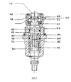
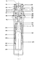
- Embodiments of the present valve cartridge 30 shown in Figures 1-3 were developed with a view to replacing the washer 20, spindle 22, and crown 28 of a conventional tap or valve 10. However, these and other embodiments may be used in different types of valves and in different applications (eg. in valves in white goods or in parts washing machines).
- the valve cartridge 30 comprises a housing 32 which is adapted for coupling to a tap 10 by virtue of a screw thread 34 provided about an outer circumferential surface of an upper length of the housing 32.
- An axially extending cavity 36 is formed centrally through the housing 32.
- a piston 38 Disposed, at least partially, within the cavity 36 is a piston 38 which, as explained in greater detail below, can be moved axially to open and close a valve 10 in which the cartridge 30 is installed.
- a flow chamber element 40 is provided at the end of the housing 32 which carries the thread 34.
- the flow chamber element 40 includes a first seal 42 for sealing against valve seat 18 of valve 10.
- a piston seal 44 against which the piston 38 can abut to prevent the flow of fluid (eg. water) through the flow chamber.
- fluid eg. water
- the piston 38 is moved axially by an actuator, without rotation, between a closed position in which it abuts the seal 44 and a fully open position in which it is spaced by a maximum predetermined distance from the seal 44.
- the actuator is in the form of a rotatable spindle 46.
- the actuator is in the form of a solenoid 48 with push rod 50.
- both the spindle 46 and solenoid/push rod 50 act to move the piston 38 axially without any rotation and to close the piston 38 onto the seal 44 with a predetermined pressure.
- the housing 32 is threadingly coupled by thread 34 to the valve body 12.
- the first seal 42 seals against the valve seat 18.
- the piston 38 is axially moved within the housing 32 and flow chamber element 40 between the closed position in which it abuts the piston seal 44 and a fully open position in which it is spaced by some maximum distance from the seal 44 to provide maximum water flow.
- the flow chamber element 40 is made from two main parts 52 and 54 which are press-fit together.
- Part 54 which is at the distant end of the cartridge 30 is substantially cylindrical in form with an increased diameter portion 56 (refer Figure 2) at the upstream end.
- the increased diameter portion 56 is provided with an annular recess 58 for seating the seal 42.
- the first part 52 is also substantially cylindrical in form but is provided with a radially inwardly extending wall 60 at an end adjacent the housing 32.
- a hole 62 coaxial with cavity 36 and through which the piston 38 extends is formed in the wall 60.
- the piston seal 44 is seated on the interior surface of the wall 60. Stop means in the form of spaced apart lugs 64 are formed about the circumference of the first part 52 on the side of wall 60 opposite the piston seal 44. The lugs 64 extend radially inwardly into the cavity 36 so as to be able to abut base 66 of the piston 38.
- the second part 54 press-fits into the first part 52 to the extent that it bears against the piston seal 44.
- first and second parts 52 and 54 When the first and second parts 52 and 54 are press-fit together, they define a cavity 68 in which is housed a non-return valve 70.
- the non-return valve 70 is arranged so as to prevent the flow of water in the direction from the outlet 16 to inlet 14.
- the components of the flow chamber 40 are dimensioned so that even when piston 38 is in the fully open position (ie. spaced from the seal 44 by a maximum displacement), it does not cause the non-return valve 70 to close the flow chamber 40.
- Piston 38 comprises a disc-like head 72 which tapers to a stem 74 on the side which abuts the piston seal 44.
- the stem 74 is integrally formed with base 66.
- the base 66 is disc like and is formed with a circumferential groove 76 which receives an O-ring 78.
- An axially extending wall 80 is provided partially about the circumference of base 66 on a side opposite the stem 74.
- An inwardly extending lip 82 is formed along the circumferential end of wall 80.
- Piston 38 is coupled to spindle 46 by coupling 84.
- the coupling 84 includes a knob 86 at one end which can be received by the lip 82 so as to couple the piston 38 to the coupling 84 in a manner which allows relative rotation therebetween.
- a circumferential groove 88 is formed about the exterior surface of the coupling 84 for receiving O-ring 90 (shown in Figure 1).
- a blind threaded hole 85 is cut axially in the coupling 84 for engaging thread 87 of spindle 46.
- a number of spaced apart fingers 94 which extend in the axial direction are provided about the circumference of the coupling 84 at an end opposite the knob 86.
- a projection 92 is formed at the tip of each finger on a side facing the circumferential wall of the cavity 36.
- Housing 32 is provided with an annular flange 96 adjacent the inboard end of thread 34.
- the flange 96 forms a seat for O-ring 98.
- the flange 96 presses the O-ring 98 onto the body 12 to form a fluid seal.
- a rebate 100 is formed in the housing 32 at an opposite end of the thread 34 for receiving the lugs 64.
- the outer diameter of the rebate 100 is slightly smaller than the outer diameter of the lugs 64 so as to form a press-fit between the chamber 40 and housing 32.
- the circumferential surface of cavity 36 at an end opposite the rebate 100 is provided with a plurality of spaced apart axially extending grooves 102.
- the grooves 102 together with fingers 94 and projections 92 form a detent means or system, or perhaps more accurately a ratchet mechanism, for resisting rotation of the coupling 84, and thus the piston 38, when the spindle 46 is turned clockwise or anticlockwise.
- the spindle 46 is rotatably held and axially fixed within the housing 32 by a circlip or lock washer 104 which sits within a circumferential groove 106 formed about a part of the spindle 46 that lies outside of the body 32.
- the remaining length of the spindle 46 outside of the body 32 is formed in a conventional manner and includes a knurled boss 108 and threaded rectangular section post 110 for receiving a conventional handle such as handle 24 shown in Figure 4.
- the spindle 46 can now be rotated in an anticlockwise direction. Because the spindle 46 is axially fixed to the housing 32, this rotation forces the coupling 84 and thus piston 38 axially away from the spindle 46. This lifts the piston head 72 from the seal 44 allowing water to flow through the flow chamber element 40, hole 62 and the spaces between the lugs 64. Rotation of the coupling 84 prior to the piston 34 being moved to its fully opened position is resisted by, the projections 92 being located within respective ones of the grooves 102. (If the coupling 84 were to rotate at this time with the spindle 46, the piston would not move axially and there be stuck in one position).
- the spindle 46 is prevented from disengaging from the coupling 84 by abutment of the lugs 64 with the base 66 of the piston 38. This abutment also denotes the fully open position of the cartridge 30. Any further rotation of the spindle 46 in the clockwise direction results in the coupling 84 turning with the spindle 46 with the knob 86 turning inside the lip 82. At this point, the projections 92 are outside of the grooves 102 or alternately the fingers 94 can flex inwardly to ratchet grooves 102 thereby allowing the coupling 84 to turn.
- housing 32' opposite the flow chamber 40 is also of a slightly different configuration in order to allow connection to the solenoid 48.
- This end is provided with a threaded boss 112 for receiving a mounting thread 114 of the solenoid 48.
- a circumferential recess 116 is also formed about the free end of the boss 112 to receive solenoid housing 118.
- housing 118 Enclosed within housing 118 is the solenoid coil 120 and solenoid return spring 122.
- the return spring 122 is bound between washer 124 located about an end of push rod 50 distant housing 32' and a base plate 126 spaced from the washer 124 toward the housing 32'.
- Base plate 126 is seated on shoulder 128 formed on the inner circumferential surface of the housing 118.
- Current carrying wires for energising the coils 120 pass through the housing 118, but are not shown in this figure.
- the solenoid 48 When the solenoid 48 is energised the push rod 50 moves linearly toward flow chamber 40 lifting the piston 38 from the seal 44. This allows water to flow through the flow chamber 40 from inlet 14 to outlet 16.
- the return spring 120 forces the push rod 50 to move linearly away from flow chamber 40 thereby pressing the piston 38 and particular piston head 72 against the seal 44. This closes the flow chamber element 40 preventing the flow of water from inlet 14 the outlet 16.
- the pressure applied by the piston to the seal 44 is fixed by the return spring 122.
- valve cartridge 30 shown in Figures 1 and 2 the axial position of spindle 46 is fixed while the axial position of coupling 84 can vary in response to rotation of the spindle 46.
- this can be reversed with the axial position of the spindle 46 being variable and the actual position of the coupling 84 being fixed.
- knob 86 and lip 82 arrangement for providing rotational coupling between the piston 38 and coupling 84 can be replaced with any mechanical equivalent which achieves the same effect. It will be recalled that the spindle 46 cannot be screwed entirely out of the coupling 84 because of the abutment between lugs 64 and base 66 of the piston 38. However, in an earlier working prototype maintaining a connection between the spindle 46 and coupling 84 was achieved by providing a circumferential flange about the spindle 46 adjacent thread 87 and forming diametrically opposed claws on the coupling 84 which can grip the flange.
- the claws were in the form of upstanding lugs which extend partially about the circumference of the coupling 84 and each provided with a lip on its inner surface which extends radially inwardly for sitting over the flange.
- the upstanding lugs are either made of flexible material or flexibly mounted on the coupling 84 so that they can be pushed apart by the flange when the spindle 46 is initially threaded into the coupling 84. With this arrangement, when the spindle is rotated a predetermined number of revolutions in the anti-clockwise direction, moving the piston 38 to the fully opened position, the flange about the spindle 46 abuts the lips on the upstanding lugs.
- the lugs are housed within the cavity 36 they are prevented from flexing radially outwardly in response to further anti-clockwise rotation of the spindle 46. In this way the coupling 84 and spindle 46 are effectively locked together so that the coupling 84 now rotates with the spindle 46 in response to any further rotation in the anti-clockwise direction.
- cartridge 130 modifications can be made so as to allow the amount of separation between the piston head 72 and seal 44 to be varied. This provides a variable flow control of the solenoid operated valve cartridge 130. This can be achieved either mechanically or electrically.
- Embodiments of this invention can of course be used in valves for controlling flow of gases and other fluids.
- the component parts of the valve cartridges 30 and 130 can be made of plastics materials and/or metals or metal alloys such as brass.
Landscapes
- Engineering & Computer Science (AREA)
- General Engineering & Computer Science (AREA)
- Mechanical Engineering (AREA)
- Physics & Mathematics (AREA)
- Electromagnetism (AREA)
- Lift Valve (AREA)
- Mechanically-Actuated Valves (AREA)
- Fluid-Driven Valves (AREA)
- Details Of Valves (AREA)
- Preventing Unauthorised Actuation Of Valves (AREA)
Claims (15)
- Eine Ventilpatrone für ein Ventil, das einen Flüssigkeitseinlass (14), einen Flüssigkeitsabfluss (16) und einen Ventilsitz (18) hat und die Flüssigkeitsübermittlung zwischen besagtem Flüssigkeitseinlass und Flüssigkeitsabfluss herstellt; besagte Ventilpatrone schließt mit ein:wobei, wenn besagtes Gehäuse an besagtes Ventil angeschlossen ist, die besagte erste Dichtung (42) dem Ventilsitz anliegt und besagter Antrieb (46) so betrieben werden kann, dass sich besagter Kolben axial durch die besagte Kammer zwischen besagter geschlossener Einstellung und besagter voll geöffneter Einstellung bewegen kann, um den Flüssigkeitsstrom von besagtem Einlass zum besagten Abfluss zu regulieren.ein der Kupplung zu besagtem Ventil angepasstes Gehäuse (32), besagtes Gehäuse ist mit einer axial verlängerten ersten Kammer (36) versehen;ein sich innerhalb der ersten Kammer bewegender Kolben (38) zur Regulierung des Flüssigkeitstroms durch besagtes Ventil;ein an einem Ende des besagten Gehäuses angebrachtes Flusskammerelement (40) und durch welches sich der besagte Kolben bewegen kann, besagtes Flusskammerelement hat eine erste Dichtung (42) zum Abdichten des besagten Ventilsitzes und eine Kolbendichtung (44) flussabwärts der besagten ersten Abdichtung, die der besagte Kolben verschließen kann, um den Flüssigkeitsstrom durch besagtes Flusskammerelement zu unterbinden; weiterhin gehören zum besagten Flusskammerelement Stopvorrichtungen, die den Gang des besagten Kolbens über die Achse hinaus verhindern, zur Stopvorrichtung gehört eine Vielzahl von in Abständen angebrachten Zinken (64), die so um den Umfang an einem Ende des besagten Flusskammerelements angebracht sind, dass sie dem einen, besagten Ende des besagten Gehäuses anliegen, besagte Zinken erstrecken sich strahlenförmig in die besagte erste Kammer (36), um somit den Gang des besagten Kolbens (38) darüber hinaus zu verhindern, die Abstände zwischen den nebeneinanderliegenden Zinken (64) bilden Öffnungen, durch die Flüssigkeit im Strom von besagtem Einlass zum besagten Abfluss fließen kann, besagter Kolben und Flusskammerelement im Verhältnis zum besagten Ventil plaziert, sodass der Flüssigkeitsdruck den besagten Kolben in eine Richtung gegen die besagte Kolbendichtung (44) treibt; und,ein Antrieb (46), der besagten Kolben axial und ohne Drehung bewegt zwischen einer geschlossenen Einstellung, in welcher der besagte Kolben (38) der besagten Kolbendichtung (44) anliegt mit vorherbestimmtem Druck, um den Flüssigkeitsstrom durch besagtes Flusskammerelement zu verhindern und einer weit geöffneten Einstellung, in welcher der besagte Kolben von der besagten Kolbendichtung verdrängt wird und gegen die besagte Stopvorrichtung drückt, um somit maximalen Flüssigkeitsdurchfluss durch besagtes Flusskammerelement zu ermöglichen;
- Eine Ventilpatrone gemäß Patentanspruch 1, worin besagtes Flusskammerelement (40) separat vom besagten Gehäuse ist und reibungsmäßig mit dem einen besagten Ende des besagten Gehäuses verbunden ist.
- Eine Ventilpatrone gemäß Patentanspruch 2, worin das eine besagte Ende des besagten Gehäuses mit einer umlaufenden Fuge (100) versehen ist, wohinein besagte Zinken (64) passen.
- Eine Venulpatrone gemäß Patentanspruch 4, worin der äußere Umfang der besagten umlaufenden Fuge (100) kleiner ist als der äußere Umfang der besagten Zinken (64), sodass es eine Presspassung zwischen der besagten umlaufenden Fuge und den besagten Zinken formt, und somit das besagte Flusskammerelement an besagtes Gehäuse hält.
- Eine Ventilpatrone gemäß Patentanspruch 1, worin besagtes Flusskammerelement (40) aus einem ersten Teil (52) besteht, zu dem besagte Zinken (64) und besagte Kolbendichtungen (44) gehören und einem zweiten Teil (54), zu dem die besagte erste Dichtung (42) gehört; besagtes erstes und zweites Teil werden durch Presspassung zusammengehalten.
- Eine Ventilpatrone gemäß Patentanspruch 5, worin die besagten ersten (52) und zweiten Teile (54) eine zweite Kammer (68) bilden, zwischen denen sich ein Rückschlagventil (70) befindet, um den Flüssigkeitsrückfluss durch besagtes Flusskammer-element vom besagten Abfluss in Richtung des besagten Einlasses zu verhindern.
- Eine Ventilpatrone gemäß Patentanspruch 6, worin der besagte Antrieb aus einem elektropneumatischen Ventil (48) besteht, welches an den besagten Kolben gekuppelt ist.
- Eine Ventilpatrone gemäß Patentanspruch 7, worin die lineare Position des besagten elektropneumatischen Ventils (48) innerhalb des besagten Gehäuses eingestellt werden kann, um die Position des Kolbens (38) in der weit geöffneten Einstellung zu verändern und somit den Durchfluss von Flüssigkeit durch besagtes Ventil stetig zu ändern
- Eine Ventilpatrone gemäß Patentanspruch 6, worin der besagte Antrieb aus einer drehbaren Spindel (46) besteht, unterstützt durch besagtes Gehäuse und verlängert durch besagte erste Kammer (36), besagte Spindel ist in einer Weise an den besagten Kolben gekuppelt, dass die Drehung einer vorgegebenen Anzahl von Umdrehungen der besagten Spindel zuerst relative Achsenbewegung zwischen besagtem Kolben und besagter Spindel in eine erste Richtung verursacht, worauf die relative Axialposition besagter Spindel und Kolben unverändert bleibt als Reaktion auf weitere Drehungen besagter Spindel im besagten ersten Sinn, und die Drehung einer vorgegebenen Anzahl von Umdrehungen der besagten Spindel in die Gegenrichtung verursacht relative Axialbewegung besagter Spindel und Kolben in die Gegenrichtung worauf die relative Axialposition besagter Spindel und Kolben unverändert bleibt als Reaktion auf weitere Drehungen besagter Spindel in die besagte Gegenrichtung.
- Eine Ventilpatrone gemäß Patentanspruch 9, die zusätzlich eine Kupplungsvorrichtung (84) einschließt um die besagte Spindel mit dem besagten Kolben zu kuppeln, wobei der Kolben so an die besagte Kupplungsvorrichtung gekuppelt ist, dass eine relative Drehung zwischen besagtem Kolben und besagter Kupplungsvorrichtung ermöglicht ist.
- Eine Ventilpatrone gemäß Patentanspruch 10, die zusätzlich eine Sperrklinkenvorrichtung (92, 94, 102) oder Sperrmechanismus enthält, der zwischen besagter Kupplungsvorrichtung (84) und besagtem Gehäuse (32) fungiert, um eine Drehung der besagten Kupplungsvorrichtung während der besagten vorgegebenen Anzahl von Umdrehungen der besagten Spindel zu widerstehen.
- Eine Ventilpatrone gemäß Patentanspruch 11, worin die besagte Sperrklinkenvorrichtung oder Sperrmechanismus eine Vielzahl von axial verlaufenden Rillen (102), die sich auf der Umfangsoberfläche der besagten ersten Kammer (36) befinden und mindestens einen Vorsprung (92), der mit der besagten Kupplungsvorrichtung verbunden ist und in eine der besagten Rillen eingreift, enthält.
- Eine Ventilpatrone gemäß Patentanspruch 12, worin besagte Kupplungsvorrichtung mit mindestens einem verlängerten Finger (94) versehen ist, wobei auf jedem dieser Finger besagter Vorsprung (92) gebildet ist.
- Eine Ventilpatrone gemäß Patentanspruch 13, worin besagte Kupplungsvorrichtung (84) zusätzlich eine Umfangsrille (88) mit einschliesst für das Einfassen eines Vorsprungs (82), der sich am und teilweise um den Umfang des besagten Kolbens (38) herum befindet, und somit die relative Drehung zwischen dem besagten Kolben und der besagten Kupplungsvorrichtung ermöglicht.
- Eine Ventilpatrone für ein Ventil mit Flüssigkeitseinlass (14), Flüssigkeitsabfluss (16) und einem Ventilsitz (18), welche die Flüssigkeitsübermittlung zwischen besagtem Flüssigkeitseinlass und Flüssigkeits-Abfluss herstellt; besagte Ventilpatrone schließt mit ein:wodurch, wenn besagtes Gehäuse an besagtes Ventil gekuppelt ist, besagte erste Abdichtung dem besagten Ventilsitz anliegt und besagtes elektropneumatisches Ventil (48) betätigt werden kann, um besagten Kolben axial durch besagte Kammer zwischen der geschlossenen Einstellung und der weit geöffneten Einstellung zu bewegen, um den Flüssigkeitsstrom von besagtem Einlass zum besagten Abfluss zu regulieren.Ein der Kupplung zu besagtem Ventil angepasstes Gehäuse (32), besagtes Gehäuse ist mit einer axial verlängerten ersten Kammer (36) versehenEin sich innerhalb der ersten Kammer bewegender Kolben (38) zur Regulierung des Flüssigkeitstroms durch besagtes Ventil;ein sich innerhalb der besagten ersten Kammer bewegender Kolben (38) zur Regulierung des Flüssigkeitstroms durch besagtes Ventil;ein an einem Ende des besagten Gehäuses angebrachtes Flusskammerelement (40) und durch welches sich der besagte Kolben bewegen kann, besagtes Flusskammerelement hat eine erste Dichtung (42) zum Abdichten des besagten Ventilsitzes und eine Kolbendichtung (44) flussabwärts der besagten ersten Abdichtung, die der besagte Kolben verschließen kann, um den Flüssigkeitsstrom durch besagtes Flusskammerelement zu unterbinden; weiterhin gehören zum besagten Flusskammerelement Stopvorrichtungen, die den Gang des besagten Kolbens über die Achse hinaus verhindern, zur Stopvorrichtung gehört eine Vielzahl von in Abständen angebrachten Zinken (64), die so um den Umfang an einem Ende des besagten Flusskammerelements angebracht sind, dass sie dem einen, besagten Ende des besagten Gehäuses anliegen, besagte Zinken erstrecken sich strahlenförmig in die besagte erste Kammer (36), um somit den Gang des besagten Kolbens (38) darüber hinaus zu verhindern, die Abstände zwischen den nebeneinanderliegenden Zinken (64) bilden Öffnungen, durch die Flüssigkeit im Strom von besagtem Einlass zum besagten Abfluss fließen kann, besagter Kolben und Flusskammerelement im Verhältnis zum besagten Ventil plaziert, sodass der Flüssigkeitsdruck den besagten Kolben in eine Richtung gegen die besagte Kolbendichtung (44) zu treiben neigt; und,ein elektropneumatisches Ventil (48) um besagten Kolben axial ohne Drehung zwischen der geschlossenen Einstellung, in welcher der besagte Kolben der besagten Kolbendichtung mit vorgegebenem Druck anliegt, um Flüssigkeitsentweichung durch besagtes Flusskammerelement zu verhindern und der weit geöffneten Einstellung, bei der besagter Kolben von besagter Kolbendichtung verdrängt wird und besagter Stopvorrichtung anliegt, um somit maximalen Flüssigkeitsstrom durch besagtes Flusskammerelement zu ermöglichen;
Applications Claiming Priority (3)
| Application Number | Priority Date | Filing Date | Title |
|---|---|---|---|
| AUPO4497A AUPO449797A0 (en) | 1997-01-07 | 1997-01-07 | Valve cartridge |
| AUPO004497 | 1997-01-07 | ||
| PCT/AU1998/000006 WO1998030820A1 (en) | 1997-01-07 | 1998-01-07 | Valve cartridge for lift valve having the closing pressure on the sealing limited |
Publications (3)
| Publication Number | Publication Date |
|---|---|
| EP0951621A1 EP0951621A1 (de) | 1999-10-27 |
| EP0951621A4 EP0951621A4 (de) | 2001-09-19 |
| EP0951621B1 true EP0951621B1 (de) | 2003-10-22 |
Family
ID=3798803
Family Applications (1)
| Application Number | Title | Priority Date | Filing Date |
|---|---|---|---|
| EP98900243A Expired - Lifetime EP0951621B1 (de) | 1997-01-07 | 1998-01-07 | Ventilkartusche für ein sitzventil mit begrenzung von dem schliessdruck auf der dichtung |
Country Status (9)
| Country | Link |
|---|---|
| EP (1) | EP0951621B1 (de) |
| JP (1) | JP4176839B2 (de) |
| KR (1) | KR100493474B1 (de) |
| CN (1) | CN1098428C (de) |
| AU (1) | AUPO449797A0 (de) |
| BR (1) | BR9806731A (de) |
| IL (1) | IL130826A (de) |
| NZ (1) | NZ337194A (de) |
| WO (1) | WO1998030820A1 (de) |
Families Citing this family (5)
| Publication number | Priority date | Publication date | Assignee | Title |
|---|---|---|---|---|
| AU4599901A (en) * | 2000-03-23 | 2001-10-03 | Nemanja Pesovic | A faucet valve with regulated depth of installing thereof |
| CN108194677A (zh) * | 2018-02-27 | 2018-06-22 | 苏州欧纳克纳米科技有限公司 | 一种真空压力控制阀 |
| US10962062B2 (en) * | 2019-05-17 | 2021-03-30 | Caterpillar Inc. | Unidirectional torque-transfer coupling |
| KR20220002496U (ko) | 2021-04-09 | 2022-10-18 | 이주병 | 돌 온열 소파 |
| CN117231749B (zh) * | 2023-11-10 | 2024-03-29 | 三峡金沙江云川水电开发有限公司 | 一种水电站闸门用充水阀 |
Family Cites Families (6)
| Publication number | Priority date | Publication date | Assignee | Title |
|---|---|---|---|---|
| YU41985B (en) * | 1981-09-03 | 1988-04-30 | Miodreag Stanic | Universal valve for liquid and gfaseous nonagressive fluids |
| IL82714A0 (en) * | 1986-08-13 | 1987-11-30 | Predrag Pesovic | Silent valve |
| YU47401B (sh) * | 1986-08-25 | 1995-03-27 | Stanić, Miodrag | Ventilski zatvarač |
| US4860923A (en) * | 1986-10-29 | 1989-08-29 | The Coca-Cola Company | Postmix juice dispensing system |
| WO1990010469A1 (en) * | 1989-03-07 | 1990-09-20 | Karl Holm | An atomizing nozzle device for atomizing a fluid and an inhaler |
| YU48999B (sh) * | 1994-06-29 | 2003-04-30 | Predrag PEŠOVIĆ | Ventil za vodosanitarne armature koji pri eksploataciji ne izaziva hidraulične udare u instalaciji |
-
1997
- 1997-01-07 AU AUPO4497A patent/AUPO449797A0/en not_active Abandoned
-
1998
- 1998-01-07 NZ NZ337194A patent/NZ337194A/xx unknown
- 1998-01-07 BR BR9806731-1A patent/BR9806731A/pt not_active IP Right Cessation
- 1998-01-07 IL IL13082698A patent/IL130826A/en not_active IP Right Cessation
- 1998-01-07 WO PCT/AU1998/000006 patent/WO1998030820A1/en not_active Ceased
- 1998-01-07 EP EP98900243A patent/EP0951621B1/de not_active Expired - Lifetime
- 1998-01-07 CN CN98802539A patent/CN1098428C/zh not_active Expired - Fee Related
- 1998-01-07 JP JP53041598A patent/JP4176839B2/ja not_active Expired - Fee Related
- 1998-01-07 KR KR10-1999-7006187A patent/KR100493474B1/ko not_active Expired - Fee Related
Also Published As
| Publication number | Publication date |
|---|---|
| NZ337194A (en) | 2000-03-27 |
| CN1247592A (zh) | 2000-03-15 |
| CN1098428C (zh) | 2003-01-08 |
| JP4176839B2 (ja) | 2008-11-05 |
| WO1998030820A1 (en) | 1998-07-16 |
| KR100493474B1 (ko) | 2005-06-07 |
| KR20000069972A (ko) | 2000-11-25 |
| BR9806731A (pt) | 2000-02-29 |
| EP0951621A1 (de) | 1999-10-27 |
| IL130826A0 (en) | 2001-01-28 |
| JP2001509864A (ja) | 2001-07-24 |
| AUPO449797A0 (en) | 1997-01-30 |
| EP0951621A4 (de) | 2001-09-19 |
| IL130826A (en) | 2002-08-14 |
Similar Documents
| Publication | Publication Date | Title |
|---|---|---|
| US5103857A (en) | Self closing valve assembly | |
| CA2187869C (en) | Fluid cartridge valve | |
| US5918626A (en) | Self regulating quarter turn faucet valve with no metal components | |
| JPH0627554B2 (ja) | 流体制御弁 | |
| GB2073374A (en) | Valve assembly | |
| US6189561B1 (en) | Valve cartridge for lift valve having the closing pressure on the sealing limited | |
| US4468001A (en) | Shut off valve for fluids | |
| JPH07500407A (ja) | ストップバルブ | |
| US4753418A (en) | Non-rise faucet assembly having stem locator cap to insure proper sealing | |
| US4516753A (en) | Faucet device with replaceable valve cartridge | |
| US4778149A (en) | Silent valve | |
| WO1991019122A1 (en) | Improved knifegate valve | |
| HU205435B (en) | Closing valve for fluids | |
| US20050022885A1 (en) | Multi-port diverter valve assembly with integral detent | |
| GB2031125A (en) | Valve | |
| EP0951621A1 (de) | Ventilkartusche für ein sitzventil mit begrenzung von dem schliessdruck auf der dichtung | |
| US6311948B1 (en) | Fluid valve assembly | |
| EP1230501B1 (de) | Ventildichtungsvorrichtung | |
| AU723388B2 (en) | Valve cartridge for lift valve having the closing pressure on the sealing limited | |
| US4611788A (en) | Combination seat and seal device | |
| US3465782A (en) | Float actuated rotary valve | |
| GB2167837A (en) | Improvements in valves | |
| US3656512A (en) | Mixing valve | |
| US6164330A (en) | Valve having a flow blocking rotary body | |
| JP7425522B2 (ja) | 流量制御弁 |
Legal Events
| Date | Code | Title | Description |
|---|---|---|---|
| PUAI | Public reference made under article 153(3) epc to a published international application that has entered the european phase |
Free format text: ORIGINAL CODE: 0009012 |
|
| 17P | Request for examination filed |
Effective date: 19990806 |
|
| AK | Designated contracting states |
Kind code of ref document: A1 Designated state(s): CH DE DK ES FI FR GB GR IE IT LI NL PT SE |
|
| A4 | Supplementary search report drawn up and despatched |
Effective date: 20010803 |
|
| AK | Designated contracting states |
Kind code of ref document: A4 Designated state(s): CH DE DK ES FI FR GB GR IE IT LI NL PT SE |
|
| GRAH | Despatch of communication of intention to grant a patent |
Free format text: ORIGINAL CODE: EPIDOS IGRA |
|
| GRAS | Grant fee paid |
Free format text: ORIGINAL CODE: EPIDOSNIGR3 |
|
| GRAA | (expected) grant |
Free format text: ORIGINAL CODE: 0009210 |
|
| AK | Designated contracting states |
Kind code of ref document: B1 Designated state(s): CH DE DK ES FI FR GB GR IE IT LI NL PT SE |
|
| PG25 | Lapsed in a contracting state [announced via postgrant information from national office to epo] |
Ref country code: NL Free format text: LAPSE BECAUSE OF FAILURE TO SUBMIT A TRANSLATION OF THE DESCRIPTION OR TO PAY THE FEE WITHIN THE PRESCRIBED TIME-LIMIT Effective date: 20031022 Ref country code: LI Free format text: LAPSE BECAUSE OF FAILURE TO SUBMIT A TRANSLATION OF THE DESCRIPTION OR TO PAY THE FEE WITHIN THE PRESCRIBED TIME-LIMIT Effective date: 20031022 Ref country code: IT Free format text: LAPSE BECAUSE OF FAILURE TO SUBMIT A TRANSLATION OF THE DESCRIPTION OR TO PAY THE FEE WITHIN THE PRESCRIBED TIME-LIMIT;WARNING: LAPSES OF ITALIAN PATENTS WITH EFFECTIVE DATE BEFORE 2007 MAY HAVE OCCURRED AT ANY TIME BEFORE 2007. THE CORRECT EFFECTIVE DATE MAY BE DIFFERENT FROM THE ONE RECORDED. Effective date: 20031022 Ref country code: FR Free format text: LAPSE BECAUSE OF FAILURE TO SUBMIT A TRANSLATION OF THE DESCRIPTION OR TO PAY THE FEE WITHIN THE PRESCRIBED TIME-LIMIT Effective date: 20031022 Ref country code: FI Free format text: LAPSE BECAUSE OF FAILURE TO SUBMIT A TRANSLATION OF THE DESCRIPTION OR TO PAY THE FEE WITHIN THE PRESCRIBED TIME-LIMIT Effective date: 20031022 Ref country code: CH Free format text: LAPSE BECAUSE OF FAILURE TO SUBMIT A TRANSLATION OF THE DESCRIPTION OR TO PAY THE FEE WITHIN THE PRESCRIBED TIME-LIMIT Effective date: 20031022 |
|
| REG | Reference to a national code |
Ref country code: GB Ref legal event code: FG4D |
|
| REG | Reference to a national code |
Ref country code: CH Ref legal event code: EP |
|
| REG | Reference to a national code |
Ref country code: IE Ref legal event code: FG4D |
|
| REF | Corresponds to: |
Ref document number: 69819132 Country of ref document: DE Date of ref document: 20031127 Kind code of ref document: P |
|
| PG25 | Lapsed in a contracting state [announced via postgrant information from national office to epo] |
Ref country code: IE Free format text: LAPSE BECAUSE OF NON-PAYMENT OF DUE FEES Effective date: 20040107 |
|
| PG25 | Lapsed in a contracting state [announced via postgrant information from national office to epo] |
Ref country code: SE Free format text: LAPSE BECAUSE OF FAILURE TO SUBMIT A TRANSLATION OF THE DESCRIPTION OR TO PAY THE FEE WITHIN THE PRESCRIBED TIME-LIMIT Effective date: 20040122 Ref country code: GR Free format text: LAPSE BECAUSE OF FAILURE TO SUBMIT A TRANSLATION OF THE DESCRIPTION OR TO PAY THE FEE WITHIN THE PRESCRIBED TIME-LIMIT Effective date: 20040122 Ref country code: DK Free format text: LAPSE BECAUSE OF FAILURE TO SUBMIT A TRANSLATION OF THE DESCRIPTION OR TO PAY THE FEE WITHIN THE PRESCRIBED TIME-LIMIT Effective date: 20040122 |
|
| PG25 | Lapsed in a contracting state [announced via postgrant information from national office to epo] |
Ref country code: DE Free format text: LAPSE BECAUSE OF FAILURE TO SUBMIT A TRANSLATION OF THE DESCRIPTION OR TO PAY THE FEE WITHIN THE PRESCRIBED TIME-LIMIT Effective date: 20040123 |
|
| PG25 | Lapsed in a contracting state [announced via postgrant information from national office to epo] |
Ref country code: ES Free format text: LAPSE BECAUSE OF FAILURE TO SUBMIT A TRANSLATION OF THE DESCRIPTION OR TO PAY THE FEE WITHIN THE PRESCRIBED TIME-LIMIT Effective date: 20040202 |
|
| NLV1 | Nl: lapsed or annulled due to failure to fulfill the requirements of art. 29p and 29m of the patents act | ||
| REG | Reference to a national code |
Ref country code: CH Ref legal event code: PL |
|
| PLBE | No opposition filed within time limit |
Free format text: ORIGINAL CODE: 0009261 |
|
| STAA | Information on the status of an ep patent application or granted ep patent |
Free format text: STATUS: NO OPPOSITION FILED WITHIN TIME LIMIT |
|
| 26N | No opposition filed |
Effective date: 20040723 |
|
| REG | Reference to a national code |
Ref country code: IE Ref legal event code: MM4A |
|
| EN | Fr: translation not filed | ||
| PGFP | Annual fee paid to national office [announced via postgrant information from national office to epo] |
Ref country code: GB Payment date: 20070103 Year of fee payment: 10 |
|
| PG25 | Lapsed in a contracting state [announced via postgrant information from national office to epo] |
Ref country code: PT Free format text: LAPSE BECAUSE OF NON-PAYMENT OF DUE FEES Effective date: 20040322 |
|
| GBPC | Gb: european patent ceased through non-payment of renewal fee |
Effective date: 20080107 |
|
| PG25 | Lapsed in a contracting state [announced via postgrant information from national office to epo] |
Ref country code: GB Free format text: LAPSE BECAUSE OF NON-PAYMENT OF DUE FEES Effective date: 20080107 |