EP0951981A2 - Système de conditionnement thermique multi-voies - Google Patents
Système de conditionnement thermique multi-voies Download PDFInfo
- Publication number
- EP0951981A2 EP0951981A2 EP99104258A EP99104258A EP0951981A2 EP 0951981 A2 EP0951981 A2 EP 0951981A2 EP 99104258 A EP99104258 A EP 99104258A EP 99104258 A EP99104258 A EP 99104258A EP 0951981 A2 EP0951981 A2 EP 0951981A2
- Authority
- EP
- European Patent Office
- Prior art keywords
- temperature control
- hydraulic
- bus
- electrical
- circuit
- Prior art date
- Legal status (The legal status is an assumption and is not a legal conclusion. Google has not performed a legal analysis and makes no representation as to the accuracy of the status listed.)
- Withdrawn
Links
- 230000003750 conditioning effect Effects 0.000 title 1
- 239000000498 cooling water Substances 0.000 claims abstract description 10
- 238000010438 heat treatment Methods 0.000 claims abstract description 6
- 239000012530 fluid Substances 0.000 claims abstract description 4
- 239000002826 coolant Substances 0.000 claims description 6
- 238000001746 injection moulding Methods 0.000 claims description 5
- 238000001816 cooling Methods 0.000 claims description 3
- 238000005516 engineering process Methods 0.000 claims description 3
- 238000005086 pumping Methods 0.000 claims description 3
- 238000007599 discharging Methods 0.000 claims 1
- 230000008878 coupling Effects 0.000 description 10
- 238000010168 coupling process Methods 0.000 description 10
- 238000005859 coupling reaction Methods 0.000 description 10
- 238000009434 installation Methods 0.000 description 5
- 238000005496 tempering Methods 0.000 description 5
- 230000004888 barrier function Effects 0.000 description 3
- 239000003795 chemical substances by application Substances 0.000 description 2
- 238000010616 electrical installation Methods 0.000 description 2
- 238000002347 injection Methods 0.000 description 2
- 239000007924 injection Substances 0.000 description 2
- XLYOFNOQVPJJNP-UHFFFAOYSA-N water Substances O XLYOFNOQVPJJNP-UHFFFAOYSA-N 0.000 description 2
- 238000007792 addition Methods 0.000 description 1
- 230000015572 biosynthetic process Effects 0.000 description 1
- 230000008859 change Effects 0.000 description 1
- 238000010276 construction Methods 0.000 description 1
- 230000007547 defect Effects 0.000 description 1
- 238000011161 development Methods 0.000 description 1
- 230000018109 developmental process Effects 0.000 description 1
- 230000002349 favourable effect Effects 0.000 description 1
- 238000004519 manufacturing process Methods 0.000 description 1
- 238000000034 method Methods 0.000 description 1
- 238000000465 moulding Methods 0.000 description 1
- 230000008569 process Effects 0.000 description 1
- 230000008439 repair process Effects 0.000 description 1
- 238000000926 separation method Methods 0.000 description 1
Images



Classifications
-
- B—PERFORMING OPERATIONS; TRANSPORTING
- B29—WORKING OF PLASTICS; WORKING OF SUBSTANCES IN A PLASTIC STATE IN GENERAL
- B29C—SHAPING OR JOINING OF PLASTICS; SHAPING OF MATERIAL IN A PLASTIC STATE, NOT OTHERWISE PROVIDED FOR; AFTER-TREATMENT OF THE SHAPED PRODUCTS, e.g. REPAIRING
- B29C45/00—Injection moulding, i.e. forcing the required volume of moulding material through a nozzle into a closed mould; Apparatus therefor
- B29C45/17—Component parts, details or accessories; Auxiliary operations
- B29C45/72—Heating or cooling
- B29C45/73—Heating or cooling of the mould
- B29C45/7306—Control circuits therefor
-
- B—PERFORMING OPERATIONS; TRANSPORTING
- B29—WORKING OF PLASTICS; WORKING OF SUBSTANCES IN A PLASTIC STATE IN GENERAL
- B29C—SHAPING OR JOINING OF PLASTICS; SHAPING OF MATERIAL IN A PLASTIC STATE, NOT OTHERWISE PROVIDED FOR; AFTER-TREATMENT OF THE SHAPED PRODUCTS, e.g. REPAIRING
- B29C35/00—Heating, cooling or curing, e.g. crosslinking or vulcanising; Apparatus therefor
- B29C35/007—Tempering units for temperature control of moulds or cores, e.g. comprising heat exchangers, controlled valves, temperature-controlled circuits for fluids
-
- G—PHYSICS
- G05—CONTROLLING; REGULATING
- G05D—SYSTEMS FOR CONTROLLING OR REGULATING NON-ELECTRIC VARIABLES
- G05D23/00—Control of temperature
- G05D23/19—Control of temperature characterised by the use of electric means
- G05D23/1927—Control of temperature characterised by the use of electric means using a plurality of sensors
- G05D23/193—Control of temperature characterised by the use of electric means using a plurality of sensors sensing the temperaure in different places in thermal relationship with one or more spaces
- G05D23/1932—Control of temperature characterised by the use of electric means using a plurality of sensors sensing the temperaure in different places in thermal relationship with one or more spaces to control the temperature of a plurality of spaces
- G05D23/1934—Control of temperature characterised by the use of electric means using a plurality of sensors sensing the temperaure in different places in thermal relationship with one or more spaces to control the temperature of a plurality of spaces each space being provided with one sensor acting on one or more control means
Definitions
- the invention relates to a Multi - circuit tempering system for tempering Consumers, especially tools for the Injection molding technology with temperature control channels of the Consumer connectable temperature control units with Coolant connection, electrical connection, Pumping device, heating, cooling and control for each temperature control circuit or channel.
- Such multi-circuit temperature control systems are for Tempering especially of Plastic injection molds necessary.
- the Injection molding of large-scale and complicated Plastic parts places high demands on the Tool temperature control. Because this is always about large and heavy tools are handled by demands great performance from the temperature control units, to get the tool on the bring the required production temperature, on the other hand during the injection process in different areas of the molding transfer heat differently and sensitively must become.
- the temperature control system is modular and consists of the following components: Temperature control unit hydraulic units, Electric units, one Hydraulic bus for supply and discharge of Tempering agent, with an electric bus electrical supply and discharge lines, with several Temperature control unit electrical units on the electrical bus are easily detachable, the Temperature control unit electrical units easily detachable with the temperature control unit hydraulic units directly or are connectable via connecting cables and Temperature control unit hydraulic units easily detachable can be coupled to the hydraulic bus, which to the Temperature control channels of the consumer connected.
- the invention provides a multi-circuit temperature control system available, which consists of individual modules is constructed. It is only required to close the hydraulic bus Consumer, for example with the tool the corresponding temperature control channels install, installing for example on a console in front of the tool or attached to a bracket can, which is attached to the tool.
- On the temperature control unit hydraulic units can use this hydraulic bus in a simple way be connected, for example by Plug-in couplings with locking elements.
- electrical units can in another place for example also headquarters in one Control center to be installed, whereby just an electrical line connection between the temperature control unit and of the temperature control unit hydraulic unit must become. These electrical leads can also be designed as a plug connection.
- the formation of the multi-circuit temperature control system allows one in the event of a defect individual component only that To lock the component-controlled temperature control channel and replace the component without the other elements of the multi-circuit temperature control system should be shut down. Because the Connection of the individual components through Plug-in couplings is a simple one Coupling and uncoupling possible. If for a certain temperature control a temperature control unit hydraulic unit other service required is, a simple exchange of one Module against another module.
- the multi-circuit temperature control system according to the invention is characterized by a compact, space-saving Construction from, the installation on the Processing machine, for example on the Injection molding machine possible in a simple manner is. Because of the easy interchangeability of the Individual components can in the event of failure of one Component no failure of the whole Multi-circuit temperature control systems take place even if Individual components are replaced or repaired have to. Individual modules can be replaced be so that the exchange of modules for example with less power Modules with higher performance is possible. It can also be used to increase performance for large Consumer groups two or more temperature control groups be interconnected.
- each other independent bus systems for hydraulics and for Electrical installation is an installation different places possible, so that Hydraulic units close to the consumer and the Electrical unit on one for operation and Control favorable place can take place.
- the Number of circuits installed on a bus be theoretically unlimited, with the Feeding and draining of cooling water for example at both ends of the Hydraulic bus can be done.
- the hydraulic bus as straight horizontal laid element provided, as well as the Electric bus.
- the quick coupling connections can be designed in such a way that for example, conical guide pins are provided are that serve as pre-centering and up to an end stop in a corresponding receptacle can be inserted in the then be locked.
- the lock can for example by means of a clamping screw or a clamping lever.
- the connections of the electrical elements can be in the form of plugs and couplings can be formed.
- at the electrical installation connector be designed for data lines.
- the temperature control system is modular and consists of the following components:
- Temperature control unit hydraulic units 1 Temperature control unit 2 units
- Bus installation line (hydraulic bus 3) for access and Deriving temperature control agents
- one Electric bus installation line (electric bus 4) with electrical supply and discharge lines.
- the temperature control unit 2 are over Plug-in couplings 2.2 to the electric bus 4 or electrical outlets 4.1 des Electric bus 4 connected.
- the electric bus 4 also has a main switch 4.2 for everyone Circuits and a current entry 4.3.
- the Temperature control unit electrical units are over one Cable connection with plug connection 2.1 to the Temperature control unit hydraulic units 1 coupled. These temperature control unit hydraulic units 1 in turn are easily detachable via plug-in couplings coupled to the hydraulic bus 3.
- Each Temperature control unit hydraulic unit 1 has for example a pump for pumping around the fluid (for example cooling water), which with 1.1 is designated.
- each Temperature control unit hydraulic unit 1 a heater 1.2, a cooling water control valve 1.3 and optionally also a heat exchanger 1.4.
- the hydraulic bus 3 has at least one Coolant inlet and outlet 3.1 on the one running through the entire length of the bus Channel system feeds. Furthermore, the hydraulic bus 3 a barrier 3.2 for circulating water, so that the consumer 5 by shutting off this Barriers 3.2 and the barriers 3.3 for Separation of hydraulic bus from hydraulic unit 1 is separated. Furthermore, the Hydraulic bus a bypass channel 3.4 through which the cooling water inlet duct with the Cooling water outlet channel is connected. How clarified in particular with reference to FIG Hydraulic bus 3 through a bracket 6 to one Consumer 5 attached. On this bracket or another holder can also be the Elektrobus 4 be supported.
- the electrical unit 2 at 7 to the Electric bus is attached and otherwise via the Plug-in couplings is connected to the electric bus.
- the hydraulic unit 1 is directly connected to the Hydraulic bus 3 connected and to this attached (easily detachable by means of Plug-in couplings).
- the Hydraulic bus additional valve systems for Interconnection of several temperature control circuits for the purpose of multiplying performance.
- FIG. 3 shows the Hydraulic bus 3 a valve system for switching on a reserve group.
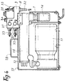
- 4 is the hydraulic bus 3 with the cooling water supply and Return channels 3.1, the circulation water and Return connections 3.2, shut-off devices 3.3, a filter 3.5 and a clamping element 3. 6 shown.
- the temperature control unit 1 with the Pump 1.1, a functional block 1.5, one Control valve 1.6, a heating insert 1.2, one Housing cover 1.7 and a mounting handle 1.8 shown.
- At 8 is a guidance system for the Coupling the temperature control unit 1 to the Hydraulic bus 3 shown.
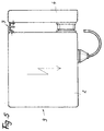
- In Figure 5 is the Electric bus 4 and the temperature control unit electric unit 2 shown.
- At 7 is the bracket the parts made clear to each other.
- it is Operating side of the electrical unit shown with Keyboards or displays can be provided.
- the invention is not based on that Embodiments limited, but in The scope of the disclosure is often variable.
Landscapes
- Engineering & Computer Science (AREA)
- Physics & Mathematics (AREA)
- Remote Sensing (AREA)
- General Physics & Mathematics (AREA)
- Automation & Control Theory (AREA)
- Health & Medical Sciences (AREA)
- Oral & Maxillofacial Surgery (AREA)
- Thermal Sciences (AREA)
- Manufacturing & Machinery (AREA)
- Mechanical Engineering (AREA)
- Injection Moulding Of Plastics Or The Like (AREA)
Applications Claiming Priority (2)
| Application Number | Priority Date | Filing Date | Title |
|---|---|---|---|
| DE19818131 | 1998-04-23 | ||
| DE19818131A DE19818131A1 (de) | 1998-04-23 | 1998-04-23 | Mehrkreistemperiersystem |
Publications (2)
| Publication Number | Publication Date |
|---|---|
| EP0951981A2 true EP0951981A2 (fr) | 1999-10-27 |
| EP0951981A3 EP0951981A3 (fr) | 2003-06-25 |
Family
ID=7865541
Family Applications (1)
| Application Number | Title | Priority Date | Filing Date |
|---|---|---|---|
| EP99104258A Withdrawn EP0951981A3 (fr) | 1998-04-23 | 1999-03-03 | Système de conditionnement thermique multi-voies |
Country Status (3)
| Country | Link |
|---|---|
| US (1) | US6463999B1 (fr) |
| EP (1) | EP0951981A3 (fr) |
| DE (1) | DE19818131A1 (fr) |
Cited By (1)
| Publication number | Priority date | Publication date | Assignee | Title |
|---|---|---|---|---|
| WO2019169415A1 (fr) * | 2018-03-07 | 2019-09-12 | Wittmann Kunststoffgeräte Gmbh | Régulateur de débit pour un appareil de traitement, en particulier une machine de moulage par injection |
Families Citing this family (20)
| Publication number | Priority date | Publication date | Assignee | Title |
|---|---|---|---|---|
| DE10033759A1 (de) * | 2000-07-12 | 2002-02-07 | Hekuma Herbst Maschb Gmbh | Verfahren und Vorrichtung zum Spitzgießen von aus mehreren Komponenten bestehenden Kunststoffartikeln |
| DE10152815C1 (de) * | 2001-10-19 | 2003-06-18 | Hekuma Gmbh | Handlinggerät für eine Kunststoff-Spritzgiessmaschine sowie Greifer für ein solches |
| DE10152816B4 (de) * | 2001-10-19 | 2004-12-30 | Hekuma Gmbh | Verfahren zum Herstellen eines mehrteiligen Kunststofferzeugnisses sowie Vorrichtung zur Durchführung des Verfahrens |
| DE10232675A1 (de) * | 2002-07-18 | 2004-02-05 | Siemens Ag | Temperiervorrichtung für ein Werkzeug einer Spritzgussmaschine |
| DE10243130B3 (de) * | 2002-09-17 | 2004-04-08 | Hekuma Gmbh | Verfahren zum Entnehmen von Spritzgussteilen aus einer Spritzgießmaschine sowie Spritzgießmaschine mit Handlingsystem |
| DE10329494B3 (de) * | 2003-06-30 | 2004-07-01 | Technotrans Ag | Temperiervorrichtung für Spritzgiesswerkzeuge |
| US20050150635A1 (en) * | 2004-01-14 | 2005-07-14 | Luebke Paul W. | Modular cooling loop system |
| JP4649897B2 (ja) * | 2004-07-09 | 2011-03-16 | ダイキン工業株式会社 | 熱搬送システム |
| US8397709B1 (en) * | 2004-12-14 | 2013-03-19 | Sentry Valve Co., Inc. | Indirect swimming pool water heating system |
| US7475827B2 (en) | 2005-04-19 | 2009-01-13 | Masco Corporation Of Indiana | Fluid mixer |
| US7458520B2 (en) | 2005-04-19 | 2008-12-02 | Masco Corporation Of Indiana | Electronic proportioning valve |
| US7448553B2 (en) | 2005-04-19 | 2008-11-11 | Masco Corporation Of Indiana | Fluid mixer |
| US7584898B2 (en) | 2005-07-01 | 2009-09-08 | Masco Corporation Of Indiana | Manual override for electronic proportioning valve |
| DE102008003724A1 (de) * | 2007-10-02 | 2009-04-09 | Netstal-Maschinen Ag | Verfahren zum Kühlen mehrerer wärmeerzeugender Komponenten sowie Kühlsysteme |
| KR100929210B1 (ko) * | 2009-04-29 | 2009-12-01 | 주식회사 삼양발부종합메이커 | 정유량 자동제어장치 |
| DE102010011084A1 (de) * | 2010-03-12 | 2011-09-15 | Converteam Gmbh | Kühlvorrichtung und Verfahren zum Kühlen eines Betriebsmittels |
| US8881719B2 (en) | 2012-04-11 | 2014-11-11 | Sentry Valve Company, Inc. | Non-pressurized indirect swimming pool water heating system |
| EP2871422B2 (fr) * | 2013-11-07 | 2020-07-29 | Grundfos Holding A/S | Distributeur hydraulique pour un système de chauffage et/ou de refroidissement hydraulique |
| CN105806506A (zh) * | 2016-06-01 | 2016-07-27 | 中冶东方工程技术有限公司 | 多回路测温系统 |
| JP7593125B2 (ja) * | 2021-01-18 | 2024-12-03 | 三浦工業株式会社 | 熱供給システム |
Family Cites Families (14)
| Publication number | Priority date | Publication date | Assignee | Title |
|---|---|---|---|---|
| US1880794A (en) * | 1930-01-06 | 1932-10-04 | Western Electric Co | Apparatus for preparing and distributing material |
| US2762652A (en) * | 1952-11-20 | 1956-09-11 | Vilbiss Co | Hot spray painting system |
| US3360032A (en) * | 1965-09-20 | 1967-12-26 | Globe Union Inc | Temperature controlling system |
| DE2916748A1 (de) * | 1979-04-25 | 1980-10-30 | Sita Bauelemente Gmbh & Co | Steuer- und/oder regelgeraet fuer heizungs-, klimatisierungs- bzw. warmwasseranlagen |
| US4261415A (en) * | 1979-10-19 | 1981-04-14 | Autoclave Engineers, Inc. | Method and apparatus for cooling a pressure vessel |
| IT8321749U1 (it) * | 1983-05-05 | 1984-11-05 | Baldini Alessandro | Unita' modulare di controllo e pompaggio per centrali termiche e simili. |
| DE8802462U1 (de) * | 1988-02-25 | 1988-08-25 | GWK Gesellschaft Wärme Kältetechnik mbH, 58566 Kierspe | Vorrichtung zur Regelung des Kühlmittelzuflusses von einem Kühlmittelspeicher zu einem Formwerkzeug für plastische Massen |
| DE68922061T2 (de) * | 1988-10-03 | 1995-08-31 | Canon Kk | Vorrichtung zum Regeln der Temperatur. |
| US5562935A (en) * | 1992-07-27 | 1996-10-08 | Master Unit Die Products, Inc. | Quick change system for mold bases |
| US5601141A (en) * | 1992-10-13 | 1997-02-11 | Intelligent Automation Systems, Inc. | High throughput thermal cycler |
| DE9319004U1 (de) * | 1993-12-10 | 1994-02-10 | Kaiser, Rolf, 73732 Esslingen | Vorrichtung zum Temperieren einer Flüssigkeit |
| US5523640A (en) * | 1994-04-22 | 1996-06-04 | Cincinnati Milacron Inc. | Liquid cooling for electrical components of a plastics processing machine |
| US5984716A (en) * | 1997-06-09 | 1999-11-16 | Progressive Components International Corporation | Electrical connection system for mold components and a plastic injection molding press |
| JP3324686B2 (ja) * | 1997-07-14 | 2002-09-17 | エスエムシー株式会社 | 恒温液循環装置 |
-
1998
- 1998-04-23 DE DE19818131A patent/DE19818131A1/de not_active Withdrawn
-
1999
- 1999-03-03 EP EP99104258A patent/EP0951981A3/fr not_active Withdrawn
- 1999-04-16 US US09/293,831 patent/US6463999B1/en not_active Expired - Fee Related
Non-Patent Citations (1)
| Title |
|---|
| None |
Cited By (1)
| Publication number | Priority date | Publication date | Assignee | Title |
|---|---|---|---|---|
| WO2019169415A1 (fr) * | 2018-03-07 | 2019-09-12 | Wittmann Kunststoffgeräte Gmbh | Régulateur de débit pour un appareil de traitement, en particulier une machine de moulage par injection |
Also Published As
| Publication number | Publication date |
|---|---|
| US6463999B1 (en) | 2002-10-15 |
| EP0951981A3 (fr) | 2003-06-25 |
| DE19818131A1 (de) | 1999-10-28 |
Similar Documents
| Publication | Publication Date | Title |
|---|---|---|
| DE19818131A1 (de) | Mehrkreistemperiersystem | |
| EP1853101B1 (fr) | Support pour composants doté d'un boîtier destiné à la réception de modules enfichables | |
| EP1719397B1 (fr) | Ensemble boitier | |
| EP1486106A1 (fr) | Ensemble de refroidissement | |
| EP0710064B1 (fr) | Module de connexion de bus de secteur | |
| EP1492384B1 (fr) | Dispositif de chauffage électrique, utilisé en particulier pour des véhicules | |
| EP1174781B1 (fr) | Appareil de transmission de signal | |
| EP0909898B1 (fr) | Unité d'entretien pour l'air comprimé | |
| EP2138023B1 (fr) | Armoire de commande ou armoire à modules connectables présentant un bloc répartiteur de fluide | |
| DE102017108183B4 (de) | Elektronikmodul zum Ankoppeln an eine Modulanordnung und Modulanordnung | |
| EP1086313B1 (fr) | Dispositif de maintenance pour systemes a air comprime | |
| EP0458832B1 (fr) | Systeme d'appareils comprenant un premier appareil electrique et au moins un deuxieme appareil electrique qui lui est couple | |
| EP1884723B1 (fr) | Module | |
| DE10314733A1 (de) | Getriebe-Wärmetauscher-Einheit | |
| DE3739815C2 (fr) | ||
| DE102006056255B4 (de) | Versorgungsmodul für Servomotoren, Schaltschrankanordnung und elektrisches System | |
| EP1555348A1 (fr) | Finisseuse | |
| DE20008411U1 (de) | Aggregatschrank für eine Druckmaschine | |
| DE102020129393A1 (de) | Leistungsmodul für eine elektrische Maschine | |
| DE202019105823U1 (de) | Integrale Kälte-/Wärmeerzeugungsvorrichtung mit modularem Aufbau | |
| DE202004010204U1 (de) | Gehäuse mit modularen elektronischen Baugruppen | |
| DE10247333A1 (de) | Mehrkanaldimmer | |
| EP1277257B1 (fr) | Batis alignables de tableaux de distribution pour unites de commutation a plusieurs tableaux de distribution | |
| DE102023209994A1 (de) | Versorgungssystem für Kühlmittelströme eines Fahrzeugs, Schnittstelleneinheit, Verteilergehäuse und Fahrzeug | |
| DE102022002189A1 (de) | Thermomanagementanordnung und Fahrzeug mit zumindest einer solchen Thermomanagementanordnung |
Legal Events
| Date | Code | Title | Description |
|---|---|---|---|
| PUAI | Public reference made under article 153(3) epc to a published international application that has entered the european phase |
Free format text: ORIGINAL CODE: 0009012 |
|
| AK | Designated contracting states |
Kind code of ref document: A2 Designated state(s): AT BE CH CY DE DK ES FI FR GB GR IE IT LI LU MC NL PT SE |
|
| AX | Request for extension of the european patent |
Free format text: AL;LT;LV;MK;RO;SI |
|
| PUAL | Search report despatched |
Free format text: ORIGINAL CODE: 0009013 |
|
| AK | Designated contracting states |
Designated state(s): AT BE CH CY DE DK ES FI FR GB GR IE IT LI LU MC NL PT SE |
|
| AX | Request for extension of the european patent |
Extension state: AL LT LV MK RO SI |
|
| 17P | Request for examination filed |
Effective date: 20031015 |
|
| AKX | Designation fees paid |
Designated state(s): AT BE CH CY DE DK ES LI |
|
| RBV | Designated contracting states (corrected) |
Designated state(s): AT BE CH DE ES FR GB IT LI NL SE |
|
| 17Q | First examination report despatched |
Effective date: 20090304 |
|
| GRAP | Despatch of communication of intention to grant a patent |
Free format text: ORIGINAL CODE: EPIDOSNIGR1 |
|
| STAA | Information on the status of an ep patent application or granted ep patent |
Free format text: STATUS: THE APPLICATION IS DEEMED TO BE WITHDRAWN |
|
| 18D | Application deemed to be withdrawn |
Effective date: 20091222 |