EP2871422B2 - Distributeur hydraulique pour un système de chauffage et/ou de refroidissement hydraulique - Google Patents
Distributeur hydraulique pour un système de chauffage et/ou de refroidissement hydraulique Download PDFInfo
- Publication number
- EP2871422B2 EP2871422B2 EP13192032.4A EP13192032A EP2871422B2 EP 2871422 B2 EP2871422 B2 EP 2871422B2 EP 13192032 A EP13192032 A EP 13192032A EP 2871422 B2 EP2871422 B2 EP 2871422B2
- Authority
- EP
- European Patent Office
- Prior art keywords
- connection
- load
- return
- control device
- hydraulic
- Prior art date
- Legal status (The legal status is an assumption and is not a legal conclusion. Google has not performed a legal analysis and makes no representation as to the accuracy of the status listed.)
- Not-in-force
Links
- 238000010438 heat treatment Methods 0.000 title claims description 36
- 238000001816 cooling Methods 0.000 title claims description 22
- 230000001105 regulatory effect Effects 0.000 claims description 38
- 239000012530 fluid Substances 0.000 claims description 35
- 238000004891 communication Methods 0.000 claims description 11
- 230000003213 activating effect Effects 0.000 claims 2
- 230000008878 coupling Effects 0.000 description 38
- 238000010168 coupling process Methods 0.000 description 38
- 238000005859 coupling reaction Methods 0.000 description 38
- 239000007788 liquid Substances 0.000 description 8
- 230000008901 benefit Effects 0.000 description 5
- 230000001276 controlling effect Effects 0.000 description 5
- XLYOFNOQVPJJNP-UHFFFAOYSA-N water Substances O XLYOFNOQVPJJNP-UHFFFAOYSA-N 0.000 description 3
- 230000004913 activation Effects 0.000 description 2
- 230000005540 biological transmission Effects 0.000 description 2
- 238000004378 air conditioning Methods 0.000 description 1
- 238000010276 construction Methods 0.000 description 1
- 230000007547 defect Effects 0.000 description 1
- 230000001419 dependent effect Effects 0.000 description 1
- 230000000694 effects Effects 0.000 description 1
- 238000005265 energy consumption Methods 0.000 description 1
- 238000009434 installation Methods 0.000 description 1
- 238000009413 insulation Methods 0.000 description 1
- 230000003993 interaction Effects 0.000 description 1
- 238000004519 manufacturing process Methods 0.000 description 1
- 238000000034 method Methods 0.000 description 1
- 230000003287 optical effect Effects 0.000 description 1
- 238000007789 sealing Methods 0.000 description 1
- 230000008054 signal transmission Effects 0.000 description 1
- 238000011144 upstream manufacturing Methods 0.000 description 1
Images


Classifications
-
- F—MECHANICAL ENGINEERING; LIGHTING; HEATING; WEAPONS; BLASTING
- F24—HEATING; RANGES; VENTILATING
- F24D—DOMESTIC- OR SPACE-HEATING SYSTEMS, e.g. CENTRAL HEATING SYSTEMS; DOMESTIC HOT-WATER SUPPLY SYSTEMS; ELEMENTS OR COMPONENTS THEREFOR
- F24D3/00—Hot-water central heating systems
- F24D3/10—Feed-line arrangements, e.g. providing for heat-accumulator tanks, expansion tanks ; Hydraulic components of a central heating system
- F24D3/1058—Feed-line arrangements, e.g. providing for heat-accumulator tanks, expansion tanks ; Hydraulic components of a central heating system disposition of pipes and pipe connections
- F24D3/1066—Distributors for heating liquids
-
- F—MECHANICAL ENGINEERING; LIGHTING; HEATING; WEAPONS; BLASTING
- F24—HEATING; RANGES; VENTILATING
- F24D—DOMESTIC- OR SPACE-HEATING SYSTEMS, e.g. CENTRAL HEATING SYSTEMS; DOMESTIC HOT-WATER SUPPLY SYSTEMS; ELEMENTS OR COMPONENTS THEREFOR
- F24D3/00—Hot-water central heating systems
- F24D3/10—Feed-line arrangements, e.g. providing for heat-accumulator tanks, expansion tanks ; Hydraulic components of a central heating system
- F24D3/1058—Feed-line arrangements, e.g. providing for heat-accumulator tanks, expansion tanks ; Hydraulic components of a central heating system disposition of pipes and pipe connections
- F24D3/1066—Distributors for heating liquids
- F24D3/1075—Built up from modules
-
- F—MECHANICAL ENGINEERING; LIGHTING; HEATING; WEAPONS; BLASTING
- F24—HEATING; RANGES; VENTILATING
- F24D—DOMESTIC- OR SPACE-HEATING SYSTEMS, e.g. CENTRAL HEATING SYSTEMS; DOMESTIC HOT-WATER SUPPLY SYSTEMS; ELEMENTS OR COMPONENTS THEREFOR
- F24D19/00—Details
- F24D19/10—Arrangement or mounting of control or safety devices
- F24D19/1006—Arrangement or mounting of control or safety devices for water heating systems
- F24D19/1009—Arrangement or mounting of control or safety devices for water heating systems for central heating
- F24D19/1015—Arrangement or mounting of control or safety devices for water heating systems for central heating using a valve or valves
- F24D19/1021—Arrangement or mounting of control or safety devices for water heating systems for central heating using a valve or valves a by pass valve
-
- F—MECHANICAL ENGINEERING; LIGHTING; HEATING; WEAPONS; BLASTING
- F24—HEATING; RANGES; VENTILATING
- F24D—DOMESTIC- OR SPACE-HEATING SYSTEMS, e.g. CENTRAL HEATING SYSTEMS; DOMESTIC HOT-WATER SUPPLY SYSTEMS; ELEMENTS OR COMPONENTS THEREFOR
- F24D3/00—Hot-water central heating systems
- F24D3/10—Feed-line arrangements, e.g. providing for heat-accumulator tanks, expansion tanks ; Hydraulic components of a central heating system
- F24D3/1091—Mixing cylinders
-
- F—MECHANICAL ENGINEERING; LIGHTING; HEATING; WEAPONS; BLASTING
- F24—HEATING; RANGES; VENTILATING
- F24D—DOMESTIC- OR SPACE-HEATING SYSTEMS, e.g. CENTRAL HEATING SYSTEMS; DOMESTIC HOT-WATER SUPPLY SYSTEMS; ELEMENTS OR COMPONENTS THEREFOR
- F24D3/00—Hot-water central heating systems
- F24D3/12—Tube and panel arrangements for ceiling, wall, or underfloor heating
- F24D3/122—Details
- F24D3/125—Hydraulic pipe connections
-
- F—MECHANICAL ENGINEERING; LIGHTING; HEATING; WEAPONS; BLASTING
- F24—HEATING; RANGES; VENTILATING
- F24D—DOMESTIC- OR SPACE-HEATING SYSTEMS, e.g. CENTRAL HEATING SYSTEMS; DOMESTIC HOT-WATER SUPPLY SYSTEMS; ELEMENTS OR COMPONENTS THEREFOR
- F24D3/00—Hot-water central heating systems
- F24D3/12—Tube and panel arrangements for ceiling, wall, or underfloor heating
- F24D3/14—Tube and panel arrangements for ceiling, wall, or underfloor heating incorporated in a ceiling, wall or floor
- F24D3/146—Tubes specially adapted for underfloor heating
-
- F—MECHANICAL ENGINEERING; LIGHTING; HEATING; WEAPONS; BLASTING
- F24—HEATING; RANGES; VENTILATING
- F24H—FLUID HEATERS, e.g. WATER OR AIR HEATERS, HAVING HEAT-GENERATING MEANS, e.g. HEAT PUMPS, IN GENERAL
- F24H1/00—Water heaters, e.g. boilers, continuous-flow heaters or water-storage heaters
- F24H1/10—Continuous-flow heaters, i.e. heaters in which heat is generated only while the water is flowing, e.g. with direct contact of the water with the heating medium
- F24H1/12—Continuous-flow heaters, i.e. heaters in which heat is generated only while the water is flowing, e.g. with direct contact of the water with the heating medium in which the water is kept separate from the heating medium
-
- Y—GENERAL TAGGING OF NEW TECHNOLOGICAL DEVELOPMENTS; GENERAL TAGGING OF CROSS-SECTIONAL TECHNOLOGIES SPANNING OVER SEVERAL SECTIONS OF THE IPC; TECHNICAL SUBJECTS COVERED BY FORMER USPC CROSS-REFERENCE ART COLLECTIONS [XRACs] AND DIGESTS
- Y10—TECHNICAL SUBJECTS COVERED BY FORMER USPC
- Y10T—TECHNICAL SUBJECTS COVERED BY FORMER US CLASSIFICATION
- Y10T137/00—Fluid handling
- Y10T137/8593—Systems
- Y10T137/85954—Closed circulating system
-
- Y—GENERAL TAGGING OF NEW TECHNOLOGICAL DEVELOPMENTS; GENERAL TAGGING OF CROSS-SECTIONAL TECHNOLOGIES SPANNING OVER SEVERAL SECTIONS OF THE IPC; TECHNICAL SUBJECTS COVERED BY FORMER USPC CROSS-REFERENCE ART COLLECTIONS [XRACs] AND DIGESTS
- Y10—TECHNICAL SUBJECTS COVERED BY FORMER USPC
- Y10T—TECHNICAL SUBJECTS COVERED BY FORMER US CLASSIFICATION
- Y10T137/00—Fluid handling
- Y10T137/8593—Systems
- Y10T137/87249—Multiple inlet with multiple outlet
Definitions
- the invention relates to a hydraulic distributor for a hydraulic heating and / or cooling system with the features specified in the preamble of claim 1.
- Hydraulic distributors are known, for example, in underfloor heating systems, from which the individual load circuits or underfloor heating circuits extend.
- the hydraulic distributor connects a plurality of load circuits to the heating system.
- the known distributors are generally essentially made up of two pipes, one of which functions as an inlet and the other as a return. Connections for the individual load circuits are arranged on the pipes. Each load circuit is connected to a connection on the inlet and a connection on the return.
- underfloor heating systems it is known in underfloor heating systems to use mixing devices or mixers which admix colder water from the return line to the fluid acting as a heat carrier in order to lower the flow temperature.
- mixers are particularly necessary when the underfloor heating is used in combination with normal radiators, since the underfloor heating requires a lower flow temperature than normal radiators.
- a central mixer is used, which is arranged upstream of the hydraulic distributor or the inlet in the hydraulic distributor.
- the flow temperature for the underfloor heating provided by the mixer is set either as a function of a room temperature sensor in a room or as a function of the outside temperature.
- the temperature of the rooms to be heated is usually set by opening and closing the individual circles of the underfloor heating.
- DE 94 11 684 U1 discloses a control device for a heating or cooling circuit, which has a plurality of pump modules, each of which serves to supply a load circuit.
- the individual pump modules are connected to a heat or cold source via a distributor module.
- the distributor module is adapted to a certain number of pump modules, ie it has as many connections as there are pump modules. This configuration therefore has the disadvantage that a suitable distributor must be kept available for each desired number of pump modules.
- the hydraulic distributor according to the invention is intended for use in a hydraulic heating and / or cooling system which has a pipeline system in which a liquid heat transfer medium, such as, for. B. water circulates.
- a liquid heat transfer medium such as, for. B. water circulates.
- This can be either an exclusive heating system, such as underfloor heating, or an exclusive cooling system or a combined system that allows both cooling and heating of objects or rooms.
- the system can be used as heating in winter and for cooling or air conditioning in summer.
- the hydraulic distributor according to the invention has an inlet line and a return line, the inlet line having at least one inlet connection and the return line having at least one return connection.
- the inlet connection and the return connection serve to connect a load circuit, for example an underfloor heating circuit.
- the inlet or the input of the load circuit is connected to the inlet connection and the outlet or return of the load circuit to the return connection.
- a plurality of inlet connections are preferably formed on the inlet line and a plurality of return connections are formed on the return line in order to be able to connect a plurality of load circuits to the hydraulic distributor.
- the hydraulic distributor according to the invention has a plurality of load modules, in each of which a section of the inlet line with at least one inlet connection and a section of the return line with a return connection are formed.
- the load modules are used to connect one load circuit to the distributor.
- the load modules each have a mixing device with a pump and a regulating valve, which are designed to mix fluid from the return line to a fluid flow from the inlet line to the inlet connection.
- a mixing device serves to reduce the flow temperature of the fluid or the liquid from the feed line by adding colder liquid from the return connection.
- the mixing device can be used to increase the flow temperature of a cold liquid flowing through the supply line by admixing warmer liquid from the return connection.
- the flow temperature of the liquid serving as heat transfer medium for the load circuit connected to the load module can be set individually by means of the mixing device.
- the regulating valve which is arranged in such a way that the degree of admixing of liquid from the return connection can be varied by its actuation.
- a temperature setting or temperature control for the load circuit is possible.
- the arrangement of the mixing device directly on the load circuit has the advantage that an individual temperature adjustment for this load circuit is possible, which is not possible with a central mixer.
- the arrangement of the mixing device in the hydraulic distributor has the advantage that the feed line to the hydraulic distributor can be integrated into a normal heating and / or cooling system without problems.
- a heating system does not require a separate feed line to the central mixer hydraulic distributor.
- the hydraulic distributor can be connected to conventional heating lines, which lead to radiators, for example. This simplifies the installation.
- the load modules each have connections for a further load module.
- the section of the feed line has an additional connection and the section of the return line has an additional connection, which can each be connected to corresponding corresponding connections of a further, preferably identical load module.
- These additional connections are preferably designed as hydraulic couplings, as described below. It is thus possible to line up several load modules, the sections of the inlet line and the sections of the return line of the respective load modules being connected to one another via the additional connections.
- the distributor has a plurality of load modules, preferably releasably connected to one another in such a way that the sections of the feed line are each connected to one another and the sections of the return line are each connected to one another.
- a separate load module with a mixing device is preferably provided for each load circuit.
- the flow temperature can be individually set for each load circuit and adapted to the heating and cooling requirements of the individual load circuit. This enables individual control for the individual load circuits or for rooms to be temperature-controlled by the load circuits, which results in energy savings and a gain in comfort.
- the modular structure of the hydraulic distributor according to the invention with individual load modules has the advantage that the hydraulic distributor can easily be adapted to the required number of load circuits, so that special hydraulic distributors do not have to be provided for different numbers of load circuits.
- the required number of load modules can be connected to one another, to build a hydraulic distributor with the desired number of load modules.
- the load modules are preferably releasably connected to one another so that they can be easily replaced in the event of defects. It is therefore not necessary to replace the entire hydraulic distributor.
- the load modules are further preferably connected, preferably detachably, to a main module which has a control device and / or an input for the feed line and / or an output for the return line.
- the main module is preferably used to connect the hydraulic distributor to supply lines which produce the inlet and the return to the hydraulic distributor from a heating or cooling system.
- the at least one load module is preferably connected to the main module such that the section of the feed line in the load module is fluidly connected to an input for the feed line on the main module.
- the section of the return line in the load module can be connected in a fluid-conducting manner to the outlet for the return line on the main module.
- Both the section of the inlet line and the section of the return line in the load module are preferably hydraulically connected to the main module in the manner mentioned.
- the hydraulic connection is preferably established via detachable couplings, in particular plug-in couplings.
- the load modules are preferably designed in such a way that they have hydraulic couplings for connection to the main module on one side and hydraulic couplings for connection to a further load module at an opposite end.
- the hydraulic couplings for connection to a further load module are expediently designed identically to the hydraulic couplings on the main module. So several load modules can be plugged together in series, preferably the sections of the Inlet line and the sections of the return line of the assembled load modules form a continuous inlet line and a continuous return line. This enables the construction of a hydraulic distributor of different lengths, depending on how many load modules are strung together.
- the main module can have a control device, for example a distributor control device, as will be described below.
- sensors can preferably be arranged in the main module, for example temperature sensors, which detect the temperature in the inlet line and / or the return line. Such sensors can be signal-connected to the control device, so that the control device can detect the temperatures directly in the main module.
- a distributor control device which is designed to control the regulating valves and / or the pumps in the plurality of load modules.
- the arrangement of a central distributor control device which controls the mixing devices of the load modules has the advantage that only one control device has to be provided for a plurality of load modules.
- the control can control or regulate several load modules in connection, for example to ensure that the available heating or cooling energy is distributed in the desired manner to the several load circuits.
- the control can also be such that the distributor control device switches the pump on and off in order to switch the associated load circuit on and off.
- a speed control of the pump is particularly preferably provided, as a result of which the flow rate or volume flow through the load circuit can also be set by the distributor control device, so that the amount of heat carrier supplied, ie. H. Fluids can be adapted to the needs of the respective load circuit by controlling the pump.
- the distributor control device is signal-connected to the load modules or the electrical components arranged in the load modules, namely the pump and / or the regulating valve, the connection taking place in particular via a data bus. It is thus possible to transmit control signals from the distributor control device to the load module or its components to be controlled or regulated. Status data or sensor signals can also be transmitted in the opposite direction via the signal connection. For example, feedback about the operating state of the regulating valve and / or the pump can be sent to the distributor control device. For example, the degree of opening of the regulating valve or the current speed of the pump can be reported back. Additional sensors, for example temperature sensors, whose signals are transmitted to the distributor control device, can be particularly preferably provided in the load modules.
- a temperature sensor can be arranged in the return connection or in the flow path between the return connection and the section of the return line in the load module in order to detect the outlet temperature of the heat transfer medium or fluid from the load circuit.
- the signal connection via a data bus is particularly advantageous when different numbers of load modules are to be strung together in the manner described above.
- Such a data bus which then preferably extends over all load modules, enables signals to be forwarded to other load modules via individual load modules.
- Each load module preferably has a module control device or a communication unit which can be uniquely addressed by the distribution control device in order to be able to exchange data and / or signals with the load module. Addressing is preferably done automatically.
- the distributor control device is particularly preferably designed such that it detects a connected load module and automatically assigns an address to the load module or its module control device.
- actuation elements can be provided on the distributor control device and / or the load module, which enable a manual activation of the coupling procedure.
- the distributor control device is particularly preferably arranged in the main module.
- the main module thus also forms the central control device for preferably the entire hydraulic distributor.
- Corresponding electrical connections in particular detachable plug connections, can be provided for the electrical or signal connection between the main module and the load module.
- the load modules also have corresponding electrical plug connections on a longitudinal end opposite the main module, which enable the electrical connection to an adjacent further load module.
- an electrical supply line for the electrical components of the load modules can extend from the main module via the plug connections through all load modules.
- a data bus can extend from the main module through the individual load modules in this way.
- the data bus can also take place via an electrical connection, or else via another suitable connection, for example an optical connection.
- At least one temperature sensor is arranged in the at least one load module, which is signal-connected to the distributor control device, in particular via a data bus.
- this can be, for example, a temperature sensor in the return of the load circuit.
- a temperature sensor is preferably arranged in each case in the load modules in such a way that it detects the temperature of a fluid to flow through the inlet connection into the connected load circuit.
- a temperature sensor is preferably located in the flow path from the mixing device to the inlet connection, so that it detects the temperature of the fluid mixed by the mixing device. This enables temperature control via the distributor control device, since the temperature set via the regulating valve in the load module is detected by the temperature sensor and feedback is thus given to the control device.
- a further temperature sensor can be provided in the return as described.
- the distributor control device is preferably designed to set the temperature of a fluid flow through the inlet connection by controlling the regulating valves in the load modules. This is preferably done in Interaction with the temperature sensor described above.
- the distributor control device particularly preferably controls the regulating valves of a plurality of load modules, so that the temperatures at the inlet connections of the individual load modules can be set centrally by the distributor control device.
- the distributor control device is further preferably designed to set a fluid flow or volume flow through the inlet connection into the connected load circuit by actuating the pumps in the load modules.
- the pumps of a plurality, preferably all, of the load modules are also controlled by the distributor control device, so that it functions as a central control of all the load circuits and, in particular, can adjust the fluid flows through the individual load circuits to one another. As described above, this is preferably done by controlling the speed of the individual pumps.
- the distributor control device has at least one communication interface for receiving signals from at least one external control element, in particular a room thermostat. It is thus possible to arrange room thermostats in the rooms to be temperature-controlled by the load circuits, which record the current temperature in the rooms and, if necessary, transmit the temperature values to the distributor control device.
- the room thermostats are particularly preferably designed such that they enable the setting of a target temperature for the respective room.
- the room thermostat sends a corresponding signal to the distributor control device via the communication interface, which then activates it depending on the load circuit or circuits belonging to the room.
- the pump described is switched on in this load circuit and is then switched on Control of the control valve (s), the adjustment of the flow temperature in the load circuits.
- the communication interface can be designed as a wired interface or, for example, also as a radio interface.
- a plurality of control elements, in particular a plurality of room thermostats, preferably communicate with the communication interface of the distributor control device. An assignment of the individual room thermostats to the connected load modules is stored or set accordingly in the control device.
- the main module has an energy supply for the pump and / or the regulating valve in the at least one load module, preferably a plurality of load modules.
- the electrical energy supply can take place, for example, via a mains connection line which is provided on the main module, via corresponding electrical connections, for example plug contacts on the main module to the load module and then from the load module to any further connected load modules.
- a corresponding power supply unit is arranged in the main module for energy supply, which has the desired, preferably lower output voltage that the load modules require as energy supply , issues. This has the particular advantage that only a central power supply unit has to be provided.
- the electrical connections between the main module and the load module or the load modules do not have to be designed for mains voltage, which simplifies the structure due to the lower insulation requirement.
- the pump is preferably arranged in a flow path between a mixing point, in which a flow path from the inlet line and a flow path from the return connection meet, and the inlet connection. This arrangement ensures that the pump can suck in fluid both through the connection to the return connection and through the connection to the feed line.
- the regulating valves in the load modules are preferably each arranged in a flow path from the return connection to a mixing point, in which a flow path from the inlet line and the flow path from the return connection meet, or in the flow path from the inlet line to the mixing point. If the flow through the regulating valve is reduced and the pump simultaneously generates a constant fluid flow, a correspondingly larger proportion is then sucked in by the pump via the mixing point from the flow path in which no regulating valve is arranged. For example, if the regulator valve is located in the flow path from the return port to the mixing point and the pump is located downstream of the mixing point in the flow path to the inlet connection, when the regulator valve is closed, the pump will only draw fluid from the connection from the mixing point to the inlet line . When the regulating valve is opened, a portion proportional to the degree of opening is sucked out of the return connection via the regulating valve.
- the mixing ratio at the mixing point can be varied and the flow temperature changed accordingly.
- the regulating valve is particularly preferably a valve driven by a motor, in particular by an electric motor.
- a stepping motor can be provided as the drive motor for the valve, so that the regulating valve can be opened and / or closed in defined steps.
- a defined degree of opening in particular proportional to a control signal, is established at the regulating valve.
- the hydraulic distributor shown and described by way of example has a modular structure. It has a main module 202 and a plurality of load modules 204.
- the main module 202 is used for the hydraulic and electrical connection of the load modules 204 and has a control device 206 which serves as a distributor control device for controlling the plurality of load modules 204.
- the main module 202 also has an inlet connection 208 and a return connection 210. With the inlet connection 208 and the return connection 210, the main module 202 is connected to a heating or cooling system. Thereby, temperature-controlled fluid is supplied through inlet connection 208, which flows after flowing through one or more load circuits through return connection 210 back into the heating or cooling system.
- a temperature sensor can be arranged in the main module 202 on the section of the inlet line 212 and / or the section of the return line 216, which detects the inlet and the return temperature. These sensors can be signal-connected to the distribution control device 206. The distributor control device 206 can thus directly detect the temperatures in the main module.
- the hydraulic distributor is further described below using the example of a heating system. However, it should be understood that the hydraulic distributor could also be used in a cooling system or in a combined heating or cooling system.
- heated fluid in particular heated water
- the fluid flows through the return connection 210 after flowing through the heat exchangers in the rooms or objects to be heated back to the boiler or the heat accumulator.
- the inlet connection 208 is connected to an outlet 214 in the interior of the main module 202 by a section of an inlet line 212.
- the return connection 210 is connected to an inlet 218 via a section of a return line 216 inside the main module 202.
- the outlet 214 and the inlet 218 are designed as hydraulic couplings on one side of the main module 202, which face an adjacent load module 204.
- the load modules 204 also each have a section of an inlet line 212 and a section of a return line 216 in their interior. The sections of the feed line 212 and the return line 216 extend in the longitudinal direction through the load modules 204.
- the sections of the feed line 212 and the return line 216 are connected to first hydraulic couplings.
- the section of the feed line 212 at the first end is connected to a first feed coupling 220 and the section of the return line 216 on the same side is connected to a first return clutch 222.
- the first inlet clutch 220 is engaged with the outlet 214 of the main module 202, while the first return clutch 222 is engaged with the inlet 218 of the main module 202 to establish a fluid-conducting connection.
- the load modules 204 have a second inlet coupling 224 and a second return coupling 226 on one of the first inlet coupling and the longitudinal end opposite the first return coupling 222.
- the second inlet clutch 224 forms the axial end of the section of the inlet line 212 in the load module 204 opposite the first inlet clutch 220
- the second return clutch 226 forms the axial end of the section of the return line 216 in the load module 204 opposite the first return clutch 222.
- the plurality of load modules 204 are all of the same design. This means that the design and arrangement of the second inlet coupling 224 and the second return coupling 226 corresponds in its design to the arrangement of the outlet 214 and the inlet 218 on the main module 202.
- FIG. 1 An arrangement of two load modules 204 is shown, further load modules 204 being indicated schematically. In the exemplary embodiment according to Figures 2 and 3 six load modules 204 are arranged on a main module 202.
- each load module 204 has an integrated mixing device for temperature adjustment of the flow temperature for an associated load circuit 228.
- the mixing device has a regulating valve 230 in a flow path from the inlet line 212 to the inlet 229 of the load circuit 228 and a circulation pump 232 downstream thereof.
- the circulation pump 232 serves to convey fluid from the feed line 212 through the load circuit 228 and via the return line 234 back into the return line 216.
- the mixing device also has a connection from the return 234 to a mixing point 236, the mixing point 236 being located in the flow path between the regulating valve 230 and the circulation pump 232.
- a check valve 238 is located in the connection 235, which has the effect that a flow through the connection 235 is only possible in the direction from the return 234 to the mixing point 236.
- the regulating valve 230 is signal-connected to the distributor control device 206 for its activation. I.e. the distributor control device 206 controls the regulating valve 230 in order to set a desired flow temperature at the input 229 of the load circuit 228. This flow temperature at input 229 is detected by a temperature sensor 240.
- the circulation pump 232 pumps fluid exclusively via the connection 235 in the circuit through the load circuit 228.
- the circulation pump 232 simultaneously causes a fluid flow from the feed line 212 and a fluid flow from the connection 235 sucked in.
- the fluid from the feed line 212 is thus mixed with fluid from the return 234 via the connection 235, so that the flow temperature of the fluid from the feed line 212 is changed.
- the supply temperature in the supply line 212 is usually higher than in the return line 234, i.e. H. in this case, colder fluid from the return line 234 is mixed in via the connection 235 to the flow from the inlet line 212, so that the inlet temperature is reduced.
- the flow temperature of the fluid from the feed line 212 can be increased by admixing warmer fluids from the return line 235.
- the proportion of fluid which is fed from the feed line 212 to the mixing point 236 can be varied.
- a constant delivery rate of the circulation pump 232 a larger or smaller proportion of the delivery flow is sucked in via the connection 235, whereby the temperature of the fluid at the inlet 229 of the load circuit 228 can be varied by changing the mixing ratio of the two flows at the mixing point 236.
- the temperature that is actually set is detected by the temperature sensor 240.
- the detected temperature value is communicated to the distribution control device 206 for regulation via a suitable signal connection. In this way, the distributor control device 206 regulates the individual load modules 204 independently, so that the flow temperature for the individual load circuits 228 can be individually regulated or set.
- a second temperature sensor 242 is also arranged at the output of the load circuit 248.
- This is also preferably signal-connected to the distributor control device 206 and detects the outlet temperature from the load circuit 228. Since the inlet and outlet temperatures of the load circuit 228 are detected in this way, it is possible to determine the temperature difference across the load circuit 228 and, for example, that of of the circulating pump 232 to regulate the volume flow depending on this temperature difference.
- the circulation pump 232 is preferably also controlled by the control device 206 via a suitable signal connection, in particular in order to set the speed of the circulation pump 232. The flow can be set individually for each load circuit by changing the speed of the respective circulation pump 232.
- the constructive structure of the on the basis of Fig. 1 described hydraulic distributor is based on the Figures 2 to 7 described.
- the main module 202 has a hydraulic section 250 and an electronics housing 252, in which the control device or distributor control device 206 and possibly further components for energy supply, such as a power supply unit, are arranged.
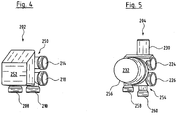
- the hydraulic section 250 is preferably designed as a one-piece component made of plastic and has the inlet connection 208 and the return connection 210 on one side.
- the inlet connection 208 and the return connection 210 are designed as hydraulic couplings for connecting supply lines which establish the connection to a heating or cooling system.
- the inlet 218 and the outlet 214 are arranged on a second side surface of the hydraulic section 250.
- the outlet 214 is connected to the inlet connection 208 via a channel inside the hydraulic section 250, while the inlet 218 is connected to the return connection 210 via another channel inside the hydraulic section 250.
- the outlet 214 and the inlet 218 are designed as hydraulic couplings for the pluggable connection of a load module 204.
- the first inlet clutch 220 of an adjacent load module 204 engages in the outlet 214 and a first return clutch 220 of an adjacent load module in the inlet 218.
- the outlet 214 and the inlet 218 are each formed as female parts of a plug-in coupling.
- the first inlet clutch 220 and the first return clutch 222 are each designed as the male parts of a hydraulic plug-in coupling.
- the load module 204 also has a housing part made in one piece from plastic, which serves as a pump housing for the circulation pump 232 and has the required flow paths and in particular the sections of the feed line 212 and the return line 216 in its interior.
- the drive of the regulating valve 230 and the stator housing 256 of the circulation pump 232 project outwards from the housing part 254.
- the housing part 254 has the first inlet coupling 220 and the first return coupling 222 at one longitudinal end and the second inlet coupling 224 and the second return coupling 226 at an opposite longitudinal end, the second inlet coupling 224 and the second return coupling 226 corresponding to the outlet 214 and the inlet 218 are formed on the main module 202 as female parts of a hydraulic plug-in coupling.
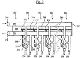
- the second inlet coupling 224 and the second return coupling 226 are shaped and arranged corresponding to the outlet 214 and the inlet 218, it is possible to connect identically designed load modules 204 either directly to the main module 202 or to a further load module 204, in which case the first inlet coupling 220 of a second load module engages in the second inlet clutch 224 of a first load module and the first return clutch 222 of a second load module in the second return clutch 226 of a first load module. In this way, several load modules can be plugged together to form a hydraulic distributor with the desired number of connections for load circuits 228.
- the number of load modules 204 is essentially limited by the configuration of control device 206.
- the housing part 254 of the load module 204 also has an inlet connection 258 and a return connection 260.
- the inlet connection 258 connects the input 229 of a load circuit 228, while the outlet connection 260 connects an output 231 of the load circuit 228.
- FIGS Figures 2 and 3 show the assembled arrangement of six load modules 204 on the main module 202 as shown in FIGS Figures 4 and 5 are shown. It can be seen that such a hydraulic distributor is created, which has six inlet connections 256 and six return connections 260 for six load circuits. All six load modules 204 are of identical design. The last, ie the load module 204 facing away from the main module 202, is closed at its second inlet coupling 224 and its second return coupling 226 by an end piece 262.
- FIG. 7 shows the structure according to Fig. 7 in the non-assembled state of the load modules 204.
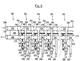
- Figures 6 and 7 only the arrangement of four load modules 204 is shown schematically.
- the main module 202 and the load modules 204 have electrical or electronic components.
- the load module has the electronic control device 206. This is connected in the main module 202 to an electrical connector 264.
- an electrical connection 266 is provided, which ends in an electrical connector 268 at a first axial end and in an electrical connector 270 at the opposite axial end.
- the electrical connector 268 and 270 are configured so that the electrical connector 268 can engage the electrical connector 264 on the main module 202 or an electrical connector 270 of an adjacent load module to form an electrical coupling and an electrical connection between the Load module 204 and an adjacent load module 204 or the main module 202 to manufacture.
- the drive of the regulating valve 230, the temperature sensor 240 and the circulation pump 232 are connected to the electrical connection 266, which is designed as a data bus, in the interior of the load module 204.
- the electrical connection 266 serves for the energy transmission to these components and also for the signal transmission to these components or from these components to the distributor control device 206 in the main module 202.
- each load module 204 is plugged into a load module 204, an energy supply of this subsequent load module 204 from the main module 202 as well as a data transmission from the main module 202 to this further load module 204 via the or the intermediate load modules 204 are manufactured.
- the individual load modules 204 can be addressed via a module control device 272 in each load module 204.
- the module control device 272 is used for data communication with the central distributor control device 206.
- each module control device 272 that is to say each load module 204, is assigned an address. This can be done automatically by the distribution control device 206 when the respective load module 204 is connected.
- the regulating valve 230 and the circulation pump 232 in each load module 204 can then be individually controlled by the distributor control device 206 in order to bring about temperature and volume flow control for the connected load circuit.
- the output signal of the temperature sensor 240 and possibly the temperature sensor 242 is reported back to the distributor control device 206 via the module control device 272 and can be incorporated there into the regulation of the respective load module 204.
- room thermostats 274 are provided in the rooms to be tempered (see Fig. 1 ).
- the room thermostats 274 communicate with a communication interface 276 of the control device 206.
- a desired target temperature can be set on the room thermostats 274. If the actual temperature deviates from this target temperature, the room thermostat 274 sends a corresponding signal to the communication sections 276 of the control device 206. The latter then activates the load circuit 228 associated with the room by switching on the circulation pump 232 in the associated load module 204 Temperature and flow control for the associated load circuit 228. If the entered target temperature is reached at the room thermostat 274, the room thermostat 274 sends a corresponding signal to the communication interface 276 of the control device 206. The latter then deactivates the associated load circuit 228, ie switches that in the respective room located load circuit 228 by the circulation pump 232 is switched off in the associated load module 204.
Landscapes
- Engineering & Computer Science (AREA)
- Physics & Mathematics (AREA)
- Thermal Sciences (AREA)
- Chemical & Material Sciences (AREA)
- Combustion & Propulsion (AREA)
- Mechanical Engineering (AREA)
- General Engineering & Computer Science (AREA)
- Steam Or Hot-Water Central Heating Systems (AREA)
- Fluid-Pressure Circuits (AREA)
Claims (14)
- Distributeur hydraulique pour système de chauffage et/ou de refroidissement hydraulique, qui comporte un conduit d'alimentation (212) et un conduit de retour (216), le conduit d'alimentation (212) étant pourvu de raccords d'alimentation (258) et le conduit de retour (216) de raccords de retour (260) pour le raccordement de plusieurs circuits de charge (228), le distributeur présentant plusieurs modules de charge (204),
caractérisé en ce que, dans chaque module de charge, un segment du conduit d'alimentation (212) est réalisé avec un raccord d'alimentation (258) et un segment du raccord de retour (216) est réalisé avec un raccord de retour (260), les modules de charge (204) comportant respectivement au moins un dispositif de mélange doté d'une pompe (232) et d'une soupape de régulation (230), lesquels sont conçus pour mélanger à un courant de fluide allant du conduit d'alimentation (212) au raccord d'alimentation (258) un fluide sortant du raccord de retour (260), et en ce que le segment du conduit d'alimentation (212) et le segment du conduit de retour (216) présentent respectivement un raccord supplémentaire pour le raccordement à un autre module de charge, et en ce que qu'est prévu un dispositif de commande de distributeur (206) qui est conçu pour la commande des soupapes de régulation (230) et/ou des pompes (232) dans lesdits plusieurs modules de charge(204). - Distributeur hydraulique selon la revendication 1, caractérisé en ce que le distributeur comporte plusieurs modules de charge (204) reliés entre eux, de préférence de manière amovible, de façon telle que les segments du conduit d'alimentation (212) sont respectivement reliés entre eux et les segments du conduit de retour (216) sont respectivement reliés entre eux.
- Distributeur hydraulique selon la revendication 1 ou 2, caractérisé en ce que le au moins un module de charge (204), est relié, de préférence de manière amovible, à un module principal (202) qui présente un dispositif de commande (206) et/ou une entrée (218) pour le conduit d'alimentation (212) et/ou une sortie (214) pour le conduit de retour (216).
- Distributeur hydraulique selon l'une des revendications précédentes, caractérisé en ce que le dispositif de commande de distributeur (206) est relié par signaux aux modules de charge (204), en particulier via un bus de données (266).
- Distributeur hydraulique selon la revendication 3, caractérisé en ce que le dispositif de commande de distributeur (206) est disposé dans le module principal (202).
- Distributeur hydraulique selon l'une des revendications précédentes, caractérisé en ce qu'est disposé dans le au moins un module de charge (204) au moins un capteur de température (240, 248) qui est relié par signaux au dispositif de commande de distributeur, en particulier via un bus de données (266).
- Distributeur hydraulique selon la revendication 6, caractérisé en ce que le capteur de température (240) est disposé dans le module de charge (204) de façon à détecter la température d'un fluide s'écoulant à travers le raccord d'alimentation (258).
- Distributeur hydraulique selon l'une des revendications précédentes, caractérisé en ce que le dispositif de commande de distributeur (206) est conçu pour régler la température d'un courant de fluide à travers le raccord d'alimentation (258) par commande de la soupape de régulation (230).
- Distributeur hydraulique selon l'une des revendications précédentes, caractérisé en ce que le dispositif de commande de distributeur (206) est conçu pour régler un courant de fluide à travers le raccord d'alimentation (258) par commande de la pompe (232).
- Distributeur hydraulique selon l'une des revendications précédentes, caractérisé en ce que le dispositif de commande de distributeur (206) présente au moins une interface de communication (276) pour la réception de signaux d'un élément de commande externe, en particulier d'un thermostat d'ambiance (274).
- Distributeur hydraulique selon l'une des revendications précédentes, caractérisé en ce que le module principal (202) est doté d'une alimentation en énergie pour la pompe (232) et la soupape de régulation (230) dans le au moins un module de charge (204), de préférence dans plusieurs modules de charge (204).
- Distributeur hydraulique selon l'une des revendications précédentes, caractérisé en ce que, dans le au moins un module de charge (204), la pompe (232) est disposée sur un trajet d'écoulement entre un point de mélange (236), où se rejoignent un trajet d'écoulement provenant du conduit d'alimentation (212) et un trajet d'écoulement provenant du raccord de retour (260), et le raccord d'alimentation (258).
- Distributeur hydraulique selon l'une des revendications précédentes, caractérisé en ce que la soupape de régulation (230) est disposée sur un trajet d'écoulement du raccord de retour (260) à un point de mélange (236), où se rejoignent un trajet d'écoulement provenant du conduit d'alimentation (212) et le trajet d'écoulement (235) provenant du raccord de retour (260), ou sur le trajet d'écoulement du conduit d'alimentation (212) au point de mélange (236).
- Distributeur hydraulique selon l'une des revendications précédentes, caractérisé en ce que la soupape de régulation (232) est une soupape à commande motorisée.
Priority Applications (4)
| Application Number | Priority Date | Filing Date | Title |
|---|---|---|---|
| DK13192032.4T DK2871422T3 (en) | 2013-11-07 | 2013-11-07 | Hydraulic distributor for a hydraulic heating and / or cooling system |
| EP13192032.4A EP2871422B2 (fr) | 2013-11-07 | 2013-11-07 | Distributeur hydraulique pour un système de chauffage et/ou de refroidissement hydraulique |
| US14/534,518 US20150122902A1 (en) | 2013-11-07 | 2014-11-06 | Hydraulic manifold for a hydraulic heating and/or cooling system |
| US16/668,711 US11243000B2 (en) | 2013-11-07 | 2019-10-30 | Hydraulic manifold for a hydraulic heating and/or cooling system |
Applications Claiming Priority (1)
| Application Number | Priority Date | Filing Date | Title |
|---|---|---|---|
| EP13192032.4A EP2871422B2 (fr) | 2013-11-07 | 2013-11-07 | Distributeur hydraulique pour un système de chauffage et/ou de refroidissement hydraulique |
Publications (3)
| Publication Number | Publication Date |
|---|---|
| EP2871422A1 EP2871422A1 (fr) | 2015-05-13 |
| EP2871422B1 EP2871422B1 (fr) | 2016-12-14 |
| EP2871422B2 true EP2871422B2 (fr) | 2020-07-29 |
Family
ID=49554079
Family Applications (1)
| Application Number | Title | Priority Date | Filing Date |
|---|---|---|---|
| EP13192032.4A Not-in-force EP2871422B2 (fr) | 2013-11-07 | 2013-11-07 | Distributeur hydraulique pour un système de chauffage et/ou de refroidissement hydraulique |
Country Status (3)
| Country | Link |
|---|---|
| US (2) | US20150122902A1 (fr) |
| EP (1) | EP2871422B2 (fr) |
| DK (1) | DK2871422T3 (fr) |
Families Citing this family (15)
| Publication number | Priority date | Publication date | Assignee | Title |
|---|---|---|---|---|
| DE202014011121U1 (de) * | 2014-05-30 | 2017-12-22 | Peter Gabanyi | Raumtemperatur-Regelung für eine Flächenheizung |
| US11357966B2 (en) * | 2015-04-23 | 2022-06-14 | B. Braun Medical Inc. | Compounding device, system, kit, software, and method |
| US11313584B2 (en) * | 2015-05-21 | 2022-04-26 | Intellihot, Inc. | Zero pressure drop water heating system |
| ES2551657B1 (es) * | 2015-07-30 | 2016-09-14 | Carlos González Bravo | Enchufe térmico para conexión y desconexión de elementos radiantes desmontables, ubicables en cualquier plano del espacio. |
| US10690356B2 (en) * | 2016-04-13 | 2020-06-23 | Paul D Mercier, SR. | Enhanced convection, differential temperature managed, hydronic heating appliance |
| DE102016115417A1 (de) * | 2016-08-19 | 2018-02-22 | Viessmann Werke Gmbh & Co Kg | Heizungsanlage |
| EP3361182B1 (fr) * | 2017-02-08 | 2020-03-25 | Grundfos Holding A/S | Module hydraulique pour une installation de chauffage ou de climatisation |
| DE102017116079A1 (de) * | 2017-07-18 | 2019-01-24 | Eisenmann Se | Versorgungskreis für ein Wärmeträgermedium für einen Verbraucher, Industrieanlage und Verfahren zum Betreiben von solchen |
| CN107883418A (zh) * | 2017-09-28 | 2018-04-06 | 天津富斯特压力容器有限公司 | 一种便于清洁的集分水器 |
| CZ308007B6 (cs) * | 2018-05-14 | 2019-10-16 | ÄŚeskĂ© vysokĂ© uÄŤenĂ technickĂ© v Praze | Zařízení pro řízení výkonu tepelného výměníku v jednopotrubní otopné síti |
| JP7202525B2 (ja) * | 2019-01-28 | 2023-01-12 | 株式会社ノーリツ | 暖房システム |
| IT201900019880A1 (it) * | 2019-10-28 | 2021-04-28 | Ivar Spa | Collettore per la distribuzione di un fluido in un impianto termoidraulico e relativo kit di distribuzione |
| CN111503704A (zh) * | 2020-04-29 | 2020-08-07 | 程恩串 | 基于人区选择的智能地暖集中供暖设备和分水器和方法 |
| EP3919821A1 (fr) * | 2020-06-04 | 2021-12-08 | Pittway Sarl | Chauffage par le sol |
| DE102022132372A1 (de) * | 2022-12-06 | 2024-06-06 | Viessmann Climate Solutions Se | Heizungsanlage |
Citations (10)
| Publication number | Priority date | Publication date | Assignee | Title |
|---|---|---|---|---|
| WO1989000633A1 (fr) † | 1987-07-21 | 1989-01-26 | Alagi Állami Tangazdaság | Procede pour la reparation sans demontage d'ouvrages d'art, d'objets, notamment d'egouts et de canalisations defectueux au niveau de la statique et de la retention d'eau |
| DE3809412A1 (de) † | 1988-03-21 | 1989-10-12 | Kamo Waermetechnische Ges Br A | Verteiler fuer heizungsanlagen |
| DE9218738U1 (de) † | 1992-03-19 | 1995-04-27 | Dumser Metallbau GmbH, 76829 Landau | Vorrichtung zur Versorgung eines Kreislaufs einer Wärme- oder Kälteversorgungsanlage |
| FR2712073A1 (fr) † | 1993-11-05 | 1995-05-12 | Comap | Installation de chauffage central. |
| WO1996009577A1 (fr) † | 1994-09-20 | 1996-03-28 | Krist Gene D | Procede, appareil et systeme d'interface hydronique |
| DE10106531A1 (de) † | 1999-12-23 | 2002-08-22 | Tekmar Holding Ltd | Rohrsystem zur Verwendung in Heißwasserverteilersystemen |
| DE10244256A1 (de) † | 2001-10-02 | 2003-04-17 | Zortea Rembert | Heizanlage und/oder Kühlanlage mit mindestens einer Wärmequelle |
| DE202005014995U1 (de) † | 2005-09-23 | 2005-12-15 | Bbt Thermotechnik Gmbh | Einrichtung zur Anbindung von mindestens zwei Heizkreisen an ein Heizgerät |
| US7191789B2 (en) † | 2003-05-02 | 2007-03-20 | Inventive Development L.L.C. | Transition adaptor and component modules for hydronic heating |
| US8251021B1 (en) † | 2007-02-02 | 2012-08-28 | Inventive Development Llc | Hydronic assembly of manifold with hydraulic separator and endsuction pumps |
Family Cites Families (17)
| Publication number | Priority date | Publication date | Assignee | Title |
|---|---|---|---|---|
| US4630221A (en) * | 1983-06-17 | 1986-12-16 | Johnson Service Company | Zone condition controller and method of using same |
| US4616325A (en) * | 1983-06-17 | 1986-10-07 | Johnson Service Company | Zone condition controller and method of using same |
| US5119988A (en) * | 1990-06-28 | 1992-06-09 | Joachim Fiedrich | Hydronic heating water temperature control system |
| DE9411684U1 (de) * | 1994-07-19 | 1994-09-15 | Elco Klöckner Heiztechnik GmbH, 72379 Hechingen | Steuervorrichtung für einen Wärme- oder Kältekreislauf |
| US6062485A (en) * | 1998-04-22 | 2000-05-16 | Erie Manufacturing Company | Radiant heating system reset control |
| DE19818131A1 (de) * | 1998-04-23 | 1999-10-28 | Gwk Ges Waerme Kaeltetechnik M | Mehrkreistemperiersystem |
| US6345770B1 (en) * | 2001-04-13 | 2002-02-12 | Thomas O. Simensen | Modular manifold |
| US7048200B2 (en) * | 2003-06-27 | 2006-05-23 | Taco, Inc. | Integrated injection-pumping fixture for transferring heat between higher and lower-temperature loops in a hydronic heating system |
| US20050258264A1 (en) * | 2004-05-21 | 2005-11-24 | Simensen Thomas O | Prefabricated stand for hydronic systems |
| US7661441B2 (en) * | 2004-05-21 | 2010-02-16 | Simensen Thomas O | Multi-line fluid conduit modules |
| WO2006041418A1 (fr) * | 2004-10-14 | 2006-04-20 | Birol Kilkis | Paroi hybride composite, panneau de plafond ou de plancher ou element de construction destines a des fonctions de chauffage, refroidissement, ventilation, climatisation et a d'autres fonctions interieures |
| DE102006010562A1 (de) * | 2006-03-06 | 2007-09-13 | Wilo Ag | Vorrichtung zum Verteilen und Regeln eines von einer Heiz- und/oder Kühlquelle stammenden Wärmeträgers |
| US7507066B2 (en) * | 2006-03-27 | 2009-03-24 | Koenig Kevin J | Pump header body and modular manifold |
| EP2191207A4 (fr) * | 2007-08-03 | 2012-03-14 | Dong-Yen Gwak | Système de commande de chauffage et procédé d'économie d'énergie |
| US7848853B2 (en) * | 2008-05-13 | 2010-12-07 | Solarlogic, Llc | System and method for controlling hydronic systems having multiple sources and multiple loads |
| FI121579B (fi) * | 2009-02-18 | 2011-01-14 | Uponor Innovation Ab | Lämmitys-/jäähdytysjärjestelmän ohjaus |
| CA2792823C (fr) * | 2011-10-21 | 2019-10-15 | Cleaver-Brooks, Inc. | Systeme et methode pour controler le taux d'allumage d'une chaudiere a condensation et sans condensation |
-
2013
- 2013-11-07 EP EP13192032.4A patent/EP2871422B2/fr not_active Not-in-force
- 2013-11-07 DK DK13192032.4T patent/DK2871422T3/en active
-
2014
- 2014-11-06 US US14/534,518 patent/US20150122902A1/en not_active Abandoned
-
2019
- 2019-10-30 US US16/668,711 patent/US11243000B2/en not_active Expired - Fee Related
Patent Citations (10)
| Publication number | Priority date | Publication date | Assignee | Title |
|---|---|---|---|---|
| WO1989000633A1 (fr) † | 1987-07-21 | 1989-01-26 | Alagi Állami Tangazdaság | Procede pour la reparation sans demontage d'ouvrages d'art, d'objets, notamment d'egouts et de canalisations defectueux au niveau de la statique et de la retention d'eau |
| DE3809412A1 (de) † | 1988-03-21 | 1989-10-12 | Kamo Waermetechnische Ges Br A | Verteiler fuer heizungsanlagen |
| DE9218738U1 (de) † | 1992-03-19 | 1995-04-27 | Dumser Metallbau GmbH, 76829 Landau | Vorrichtung zur Versorgung eines Kreislaufs einer Wärme- oder Kälteversorgungsanlage |
| FR2712073A1 (fr) † | 1993-11-05 | 1995-05-12 | Comap | Installation de chauffage central. |
| WO1996009577A1 (fr) † | 1994-09-20 | 1996-03-28 | Krist Gene D | Procede, appareil et systeme d'interface hydronique |
| DE10106531A1 (de) † | 1999-12-23 | 2002-08-22 | Tekmar Holding Ltd | Rohrsystem zur Verwendung in Heißwasserverteilersystemen |
| DE10244256A1 (de) † | 2001-10-02 | 2003-04-17 | Zortea Rembert | Heizanlage und/oder Kühlanlage mit mindestens einer Wärmequelle |
| US7191789B2 (en) † | 2003-05-02 | 2007-03-20 | Inventive Development L.L.C. | Transition adaptor and component modules for hydronic heating |
| DE202005014995U1 (de) † | 2005-09-23 | 2005-12-15 | Bbt Thermotechnik Gmbh | Einrichtung zur Anbindung von mindestens zwei Heizkreisen an ein Heizgerät |
| US8251021B1 (en) † | 2007-02-02 | 2012-08-28 | Inventive Development Llc | Hydronic assembly of manifold with hydraulic separator and endsuction pumps |
Also Published As
| Publication number | Publication date |
|---|---|
| EP2871422A1 (fr) | 2015-05-13 |
| US20200063980A1 (en) | 2020-02-27 |
| DK2871422T3 (en) | 2017-03-13 |
| US20150122902A1 (en) | 2015-05-07 |
| US11243000B2 (en) | 2022-02-08 |
| EP2871422B1 (fr) | 2016-12-14 |
Similar Documents
| Publication | Publication Date | Title |
|---|---|---|
| EP2871422B1 (fr) | Distributeur hydraulique pour un système de chauffage et/ou de refroidissement hydraulique | |
| EP2871420B1 (fr) | Module de pompe de circulation pour un système de chauffage et/ou de refroidissement | |
| EP3066395B1 (fr) | Distributeur hydraulique pour un système de chauffage et/ou de refroidissement hydraulique | |
| EP1991814B1 (fr) | Dispositif pour distribuer et reguler un fluide caloporteur issu d'une source de chauffage et/ou de refroidissement | |
| EP2151578B1 (fr) | Agrégat de pompe de recirculation | |
| EP3037704B1 (fr) | Vanne mélangeuse | |
| EP3361182B1 (fr) | Module hydraulique pour une installation de chauffage ou de climatisation | |
| EP2871423B1 (fr) | Procédé de régulation pour un système de chauffage et/ou de refroidissement comprenant au moins un circuit de charge et dispositif de distribution pour un système de chauffage et/ou de refroidissement | |
| WO2015067439A1 (fr) | Procédé de diagnostic pour diagnostiquer le bon fonctionnement d'un système de chauffage et/ou de refroidissement | |
| EP3136005A1 (fr) | Installation de chauffage et son procede de fonctionnement | |
| EP2413045B1 (fr) | Unité d'échange thermique | |
| DE102010014431B4 (de) | Verfahren und Vorrichtung zur Nutzung der Wärmeenergieresourcen eines Gebäudes | |
| EP2412981B1 (fr) | Système de pompe | |
| EP2413046B1 (fr) | Unité de chauffage d'eau domestique | |
| EP2413047A1 (fr) | Unité de chauffage d'eau potable | |
| DE102010037227A1 (de) | Wärmeversorgungsanlage mit mehreren Verbraucherkreisen | |
| EP2014992A1 (fr) | Répartiteur d'installations de température | |
| EP3376131B1 (fr) | Station d'appartement | |
| DE102015203293B4 (de) | Gebäude | |
| EP2950006B1 (fr) | Réglage de température ambiante pour un chauffage par le sol | |
| EP4411254B1 (fr) | Système d'alimentation d'une pluralité d'unités de consommation placées dans un bâtiment en exergie | |
| AT10232U1 (de) | Heizungsanlage mit mindestens einer wärmequelle | |
| DE102007015004B3 (de) | Regelsystem für Flächenheizung | |
| EP4741718A1 (fr) | Station efficace d'eau douce | |
| DE102020123687A1 (de) | Elektrischer Fluid-Luft-Wärmeübertrager für ein Fahrzeug sowie Klimagerät mit einem solchen elektrischen Fluid-Luft-Wärmeübertrager |
Legal Events
| Date | Code | Title | Description |
|---|---|---|---|
| PUAI | Public reference made under article 153(3) epc to a published international application that has entered the european phase |
Free format text: ORIGINAL CODE: 0009012 |
|
| 17P | Request for examination filed |
Effective date: 20131107 |
|
| AK | Designated contracting states |
Kind code of ref document: A1 Designated state(s): AL AT BE BG CH CY CZ DE DK EE ES FI FR GB GR HR HU IE IS IT LI LT LU LV MC MK MT NL NO PL PT RO RS SE SI SK SM TR |
|
| AX | Request for extension of the european patent |
Extension state: BA ME |
|
| R17P | Request for examination filed (corrected) |
Effective date: 20151110 |
|
| RBV | Designated contracting states (corrected) |
Designated state(s): AL AT BE BG CH CY CZ DE DK EE ES FI FR GB GR HR HU IE IS IT LI LT LU LV MC MK MT NL NO PL PT RO RS SE SI SK SM TR |
|
| REG | Reference to a national code |
Ref country code: DE Ref legal event code: R079 Ref document number: 502013005726 Country of ref document: DE Free format text: PREVIOUS MAIN CLASS: F24D0003100000 Ipc: F24H0001120000 |
|
| RIC1 | Information provided on ipc code assigned before grant |
Ipc: F24D 19/10 20060101ALI20160315BHEP Ipc: F24D 3/10 20060101ALI20160315BHEP Ipc: F24D 3/14 20060101ALI20160315BHEP Ipc: F24H 1/12 20060101AFI20160315BHEP Ipc: F24D 3/12 20060101ALI20160315BHEP |
|
| GRAP | Despatch of communication of intention to grant a patent |
Free format text: ORIGINAL CODE: EPIDOSNIGR1 |
|
| INTG | Intention to grant announced |
Effective date: 20160502 |
|
| GRAJ | Information related to disapproval of communication of intention to grant by the applicant or resumption of examination proceedings by the epo deleted |
Free format text: ORIGINAL CODE: EPIDOSDIGR1 |
|
| GRAR | Information related to intention to grant a patent recorded |
Free format text: ORIGINAL CODE: EPIDOSNIGR71 |
|
| GRAS | Grant fee paid |
Free format text: ORIGINAL CODE: EPIDOSNIGR3 |
|
| INTC | Intention to grant announced (deleted) | ||
| GRAA | (expected) grant |
Free format text: ORIGINAL CODE: 0009210 |
|
| STAA | Information on the status of an ep patent application or granted ep patent |
Free format text: STATUS: THE PATENT HAS BEEN GRANTED |
|
| INTG | Intention to grant announced |
Effective date: 20161007 |
|
| AK | Designated contracting states |
Kind code of ref document: B1 Designated state(s): AL AT BE BG CH CY CZ DE DK EE ES FI FR GB GR HR HU IE IS IT LI LT LU LV MC MK MT NL NO PL PT RO RS SE SI SK SM TR |
|
| REG | Reference to a national code |
Ref country code: GB Ref legal event code: FG4D Free format text: NOT ENGLISH |
|
| REG | Reference to a national code |
Ref country code: CH Ref legal event code: EP |
|
| REG | Reference to a national code |
Ref country code: IE Ref legal event code: FG4D Free format text: LANGUAGE OF EP DOCUMENT: GERMAN |
|
| REG | Reference to a national code |
Ref country code: AT Ref legal event code: REF Ref document number: 853957 Country of ref document: AT Kind code of ref document: T Effective date: 20170115 |
|
| REG | Reference to a national code |
Ref country code: DE Ref legal event code: R096 Ref document number: 502013005726 Country of ref document: DE |
|
| PG25 | Lapsed in a contracting state [announced via postgrant information from national office to epo] |
Ref country code: LV Free format text: LAPSE BECAUSE OF FAILURE TO SUBMIT A TRANSLATION OF THE DESCRIPTION OR TO PAY THE FEE WITHIN THE PRESCRIBED TIME-LIMIT Effective date: 20161214 |
|
| REG | Reference to a national code |
Ref country code: DK Ref legal event code: T3 Effective date: 20170309 |
|
| REG | Reference to a national code |
Ref country code: NL Ref legal event code: FP |
|
| REG | Reference to a national code |
Ref country code: LT Ref legal event code: MG4D |
|
| PG25 | Lapsed in a contracting state [announced via postgrant information from national office to epo] |
Ref country code: GR Free format text: LAPSE BECAUSE OF FAILURE TO SUBMIT A TRANSLATION OF THE DESCRIPTION OR TO PAY THE FEE WITHIN THE PRESCRIBED TIME-LIMIT Effective date: 20170315 Ref country code: NO Free format text: LAPSE BECAUSE OF FAILURE TO SUBMIT A TRANSLATION OF THE DESCRIPTION OR TO PAY THE FEE WITHIN THE PRESCRIBED TIME-LIMIT Effective date: 20170314 Ref country code: SE Free format text: LAPSE BECAUSE OF FAILURE TO SUBMIT A TRANSLATION OF THE DESCRIPTION OR TO PAY THE FEE WITHIN THE PRESCRIBED TIME-LIMIT Effective date: 20161214 Ref country code: LT Free format text: LAPSE BECAUSE OF FAILURE TO SUBMIT A TRANSLATION OF THE DESCRIPTION OR TO PAY THE FEE WITHIN THE PRESCRIBED TIME-LIMIT Effective date: 20161214 |
|
| PG25 | Lapsed in a contracting state [announced via postgrant information from national office to epo] |
Ref country code: RS Free format text: LAPSE BECAUSE OF FAILURE TO SUBMIT A TRANSLATION OF THE DESCRIPTION OR TO PAY THE FEE WITHIN THE PRESCRIBED TIME-LIMIT Effective date: 20161214 Ref country code: FI Free format text: LAPSE BECAUSE OF FAILURE TO SUBMIT A TRANSLATION OF THE DESCRIPTION OR TO PAY THE FEE WITHIN THE PRESCRIBED TIME-LIMIT Effective date: 20161214 Ref country code: HR Free format text: LAPSE BECAUSE OF FAILURE TO SUBMIT A TRANSLATION OF THE DESCRIPTION OR TO PAY THE FEE WITHIN THE PRESCRIBED TIME-LIMIT Effective date: 20161214 |
|
| PG25 | Lapsed in a contracting state [announced via postgrant information from national office to epo] |
Ref country code: CZ Free format text: LAPSE BECAUSE OF FAILURE TO SUBMIT A TRANSLATION OF THE DESCRIPTION OR TO PAY THE FEE WITHIN THE PRESCRIBED TIME-LIMIT Effective date: 20161214 Ref country code: IS Free format text: LAPSE BECAUSE OF FAILURE TO SUBMIT A TRANSLATION OF THE DESCRIPTION OR TO PAY THE FEE WITHIN THE PRESCRIBED TIME-LIMIT Effective date: 20170414 Ref country code: RO Free format text: LAPSE BECAUSE OF FAILURE TO SUBMIT A TRANSLATION OF THE DESCRIPTION OR TO PAY THE FEE WITHIN THE PRESCRIBED TIME-LIMIT Effective date: 20161214 Ref country code: SK Free format text: LAPSE BECAUSE OF FAILURE TO SUBMIT A TRANSLATION OF THE DESCRIPTION OR TO PAY THE FEE WITHIN THE PRESCRIBED TIME-LIMIT Effective date: 20161214 Ref country code: EE Free format text: LAPSE BECAUSE OF FAILURE TO SUBMIT A TRANSLATION OF THE DESCRIPTION OR TO PAY THE FEE WITHIN THE PRESCRIBED TIME-LIMIT Effective date: 20161214 |
|
| PG25 | Lapsed in a contracting state [announced via postgrant information from national office to epo] |
Ref country code: SM Free format text: LAPSE BECAUSE OF FAILURE TO SUBMIT A TRANSLATION OF THE DESCRIPTION OR TO PAY THE FEE WITHIN THE PRESCRIBED TIME-LIMIT Effective date: 20161214 Ref country code: PL Free format text: LAPSE BECAUSE OF FAILURE TO SUBMIT A TRANSLATION OF THE DESCRIPTION OR TO PAY THE FEE WITHIN THE PRESCRIBED TIME-LIMIT Effective date: 20161214 Ref country code: PT Free format text: LAPSE BECAUSE OF FAILURE TO SUBMIT A TRANSLATION OF THE DESCRIPTION OR TO PAY THE FEE WITHIN THE PRESCRIBED TIME-LIMIT Effective date: 20170414 Ref country code: BG Free format text: LAPSE BECAUSE OF FAILURE TO SUBMIT A TRANSLATION OF THE DESCRIPTION OR TO PAY THE FEE WITHIN THE PRESCRIBED TIME-LIMIT Effective date: 20170314 Ref country code: ES Free format text: LAPSE BECAUSE OF FAILURE TO SUBMIT A TRANSLATION OF THE DESCRIPTION OR TO PAY THE FEE WITHIN THE PRESCRIBED TIME-LIMIT Effective date: 20161214 Ref country code: IT Free format text: LAPSE BECAUSE OF FAILURE TO SUBMIT A TRANSLATION OF THE DESCRIPTION OR TO PAY THE FEE WITHIN THE PRESCRIBED TIME-LIMIT Effective date: 20161214 |
|
| REG | Reference to a national code |
Ref country code: DE Ref legal event code: R026 Ref document number: 502013005726 Country of ref document: DE |
|
| PLBI | Opposition filed |
Free format text: ORIGINAL CODE: 0009260 |
|
| REG | Reference to a national code |
Ref country code: FR Ref legal event code: PLFP Year of fee payment: 5 |
|
| PLAX | Notice of opposition and request to file observation + time limit sent |
Free format text: ORIGINAL CODE: EPIDOSNOBS2 |
|
| 26 | Opposition filed |
Opponent name: KSB AKTIENGESELLSCHAFT Effective date: 20170914 |
|
| PG25 | Lapsed in a contracting state [announced via postgrant information from national office to epo] |
Ref country code: SI Free format text: LAPSE BECAUSE OF FAILURE TO SUBMIT A TRANSLATION OF THE DESCRIPTION OR TO PAY THE FEE WITHIN THE PRESCRIBED TIME-LIMIT Effective date: 20161214 |
|
| PLBB | Reply of patent proprietor to notice(s) of opposition received |
Free format text: ORIGINAL CODE: EPIDOSNOBS3 |
|
| PG25 | Lapsed in a contracting state [announced via postgrant information from national office to epo] |
Ref country code: MC Free format text: LAPSE BECAUSE OF FAILURE TO SUBMIT A TRANSLATION OF THE DESCRIPTION OR TO PAY THE FEE WITHIN THE PRESCRIBED TIME-LIMIT Effective date: 20161214 |
|
| PG25 | Lapsed in a contracting state [announced via postgrant information from national office to epo] |
Ref country code: CH Free format text: LAPSE BECAUSE OF NON-PAYMENT OF DUE FEES Effective date: 20171130 Ref country code: LI Free format text: LAPSE BECAUSE OF NON-PAYMENT OF DUE FEES Effective date: 20171130 |
|
| PG25 | Lapsed in a contracting state [announced via postgrant information from national office to epo] |
Ref country code: LU Free format text: LAPSE BECAUSE OF NON-PAYMENT OF DUE FEES Effective date: 20171107 |
|
| REG | Reference to a national code |
Ref country code: BE Ref legal event code: MM Effective date: 20171130 |
|
| REG | Reference to a national code |
Ref country code: IE Ref legal event code: MM4A |
|
| PG25 | Lapsed in a contracting state [announced via postgrant information from national office to epo] |
Ref country code: MT Free format text: LAPSE BECAUSE OF FAILURE TO SUBMIT A TRANSLATION OF THE DESCRIPTION OR TO PAY THE FEE WITHIN THE PRESCRIBED TIME-LIMIT Effective date: 20161214 |
|
| PG25 | Lapsed in a contracting state [announced via postgrant information from national office to epo] |
Ref country code: IE Free format text: LAPSE BECAUSE OF NON-PAYMENT OF DUE FEES Effective date: 20171107 |
|
| PG25 | Lapsed in a contracting state [announced via postgrant information from national office to epo] |
Ref country code: BE Free format text: LAPSE BECAUSE OF NON-PAYMENT OF DUE FEES Effective date: 20171130 |
|
| PG25 | Lapsed in a contracting state [announced via postgrant information from national office to epo] |
Ref country code: HU Free format text: LAPSE BECAUSE OF FAILURE TO SUBMIT A TRANSLATION OF THE DESCRIPTION OR TO PAY THE FEE WITHIN THE PRESCRIBED TIME-LIMIT; INVALID AB INITIO Effective date: 20131107 |
|
| PG25 | Lapsed in a contracting state [announced via postgrant information from national office to epo] |
Ref country code: CY Free format text: LAPSE BECAUSE OF FAILURE TO SUBMIT A TRANSLATION OF THE DESCRIPTION OR TO PAY THE FEE WITHIN THE PRESCRIBED TIME-LIMIT Effective date: 20161214 |
|
| PG25 | Lapsed in a contracting state [announced via postgrant information from national office to epo] |
Ref country code: MK Free format text: LAPSE BECAUSE OF FAILURE TO SUBMIT A TRANSLATION OF THE DESCRIPTION OR TO PAY THE FEE WITHIN THE PRESCRIBED TIME-LIMIT Effective date: 20161214 |
|
| REG | Reference to a national code |
Ref country code: AT Ref legal event code: MM01 Ref document number: 853957 Country of ref document: AT Kind code of ref document: T Effective date: 20181107 |
|
| PG25 | Lapsed in a contracting state [announced via postgrant information from national office to epo] |
Ref country code: AT Free format text: LAPSE BECAUSE OF NON-PAYMENT OF DUE FEES Effective date: 20181107 |
|
| PG25 | Lapsed in a contracting state [announced via postgrant information from national office to epo] |
Ref country code: TR Free format text: LAPSE BECAUSE OF FAILURE TO SUBMIT A TRANSLATION OF THE DESCRIPTION OR TO PAY THE FEE WITHIN THE PRESCRIBED TIME-LIMIT Effective date: 20161214 |
|
| PUAH | Patent maintained in amended form |
Free format text: ORIGINAL CODE: 0009272 |
|
| STAA | Information on the status of an ep patent application or granted ep patent |
Free format text: STATUS: PATENT MAINTAINED AS AMENDED |
|
| 27A | Patent maintained in amended form |
Effective date: 20200729 |
|
| AK | Designated contracting states |
Kind code of ref document: B2 Designated state(s): AL AT BE BG CH CY CZ DE DK EE ES FI FR GB GR HR HU IE IS IT LI LT LU LV MC MK MT NL NO PL PT RO RS SE SI SK SM TR |
|
| REG | Reference to a national code |
Ref country code: DE Ref legal event code: R102 Ref document number: 502013005726 Country of ref document: DE |
|
| PG25 | Lapsed in a contracting state [announced via postgrant information from national office to epo] |
Ref country code: AL Free format text: LAPSE BECAUSE OF FAILURE TO SUBMIT A TRANSLATION OF THE DESCRIPTION OR TO PAY THE FEE WITHIN THE PRESCRIBED TIME-LIMIT Effective date: 20161214 |
|
| REG | Reference to a national code |
Ref country code: DK Ref legal event code: T4 Effective date: 20200928 |
|
| REG | Reference to a national code |
Ref country code: NL Ref legal event code: FP |
|
| REG | Reference to a national code |
Ref country code: DE Ref legal event code: R082 Ref document number: 502013005726 Country of ref document: DE |
|
| PGFP | Annual fee paid to national office [announced via postgrant information from national office to epo] |
Ref country code: NL Payment date: 20221118 Year of fee payment: 10 Ref country code: GB Payment date: 20221122 Year of fee payment: 10 Ref country code: FR Payment date: 20221129 Year of fee payment: 10 Ref country code: DK Payment date: 20221122 Year of fee payment: 10 Ref country code: DE Payment date: 20221123 Year of fee payment: 10 |
|
| REG | Reference to a national code |
Ref country code: DE Ref legal event code: R119 Ref document number: 502013005726 Country of ref document: DE |
|
| REG | Reference to a national code |
Ref country code: DK Ref legal event code: EBP Effective date: 20231130 |
|
| REG | Reference to a national code |
Ref country code: NL Ref legal event code: MM Effective date: 20231201 |
|
| GBPC | Gb: european patent ceased through non-payment of renewal fee |
Effective date: 20231107 |
|
| PG25 | Lapsed in a contracting state [announced via postgrant information from national office to epo] |
Ref country code: NL Free format text: LAPSE BECAUSE OF NON-PAYMENT OF DUE FEES Effective date: 20231201 |
|
| PG25 | Lapsed in a contracting state [announced via postgrant information from national office to epo] |
Ref country code: NL Free format text: LAPSE BECAUSE OF NON-PAYMENT OF DUE FEES Effective date: 20231201 |
|
| PG25 | Lapsed in a contracting state [announced via postgrant information from national office to epo] |
Ref country code: DE Free format text: LAPSE BECAUSE OF NON-PAYMENT OF DUE FEES Effective date: 20240601 |
|
| PG25 | Lapsed in a contracting state [announced via postgrant information from national office to epo] |
Ref country code: DK Free format text: LAPSE BECAUSE OF NON-PAYMENT OF DUE FEES Effective date: 20231130 |
|
| PG25 | Lapsed in a contracting state [announced via postgrant information from national office to epo] |
Ref country code: GB Free format text: LAPSE BECAUSE OF NON-PAYMENT OF DUE FEES Effective date: 20231107 |
|
| PG25 | Lapsed in a contracting state [announced via postgrant information from national office to epo] |
Ref country code: FR Free format text: LAPSE BECAUSE OF NON-PAYMENT OF DUE FEES Effective date: 20231130 |
|
| PG25 | Lapsed in a contracting state [announced via postgrant information from national office to epo] |
Ref country code: GB Free format text: LAPSE BECAUSE OF NON-PAYMENT OF DUE FEES Effective date: 20231107 Ref country code: FR Free format text: LAPSE BECAUSE OF NON-PAYMENT OF DUE FEES Effective date: 20231130 Ref country code: DK Free format text: LAPSE BECAUSE OF NON-PAYMENT OF DUE FEES Effective date: 20231130 Ref country code: DE Free format text: LAPSE BECAUSE OF NON-PAYMENT OF DUE FEES Effective date: 20240601 |