EP0952281A2 - Dispositif de clÔture - Google Patents
Dispositif de clÔture Download PDFInfo
- Publication number
- EP0952281A2 EP0952281A2 EP99107824A EP99107824A EP0952281A2 EP 0952281 A2 EP0952281 A2 EP 0952281A2 EP 99107824 A EP99107824 A EP 99107824A EP 99107824 A EP99107824 A EP 99107824A EP 0952281 A2 EP0952281 A2 EP 0952281A2
- Authority
- EP
- European Patent Office
- Prior art keywords
- fence
- base
- elements
- fence system
- attached
- Prior art date
- Legal status (The legal status is an assumption and is not a legal conclusion. Google has not performed a legal analysis and makes no representation as to the accuracy of the status listed.)
- Withdrawn
Links
Images


Classifications
-
- A—HUMAN NECESSITIES
- A63—SPORTS; GAMES; AMUSEMENTS
- A63C—SKATES; SKIS; ROLLER SKATES; DESIGN OR LAYOUT OF COURTS, RINKS OR THE LIKE
- A63C19/00—Design or layout of playing courts, rinks, bowling greens or areas for water-skiing; Covers therefor
- A63C19/06—Apparatus for setting-out or dividing courts
- A63C19/08—Mechanical means for marking-out
-
- E—FIXED CONSTRUCTIONS
- E04—BUILDING
- E04H—BUILDINGS OR LIKE STRUCTURES FOR PARTICULAR PURPOSES; SWIMMING OR SPLASH BATHS OR POOLS; MASTS; FENCING; TENTS OR CANOPIES, IN GENERAL
- E04H17/00—Fencing, e.g. fences, enclosures, corrals
- E04H17/14—Fences constructed of rigid elements, e.g. with additional wire fillings or with posts
- E04H17/16—Fences constructed of rigid elements, e.g. with additional wire fillings or with posts using prefabricated panel-like elements, e.g. wired frames
- E04H17/161—Fences constructed of rigid elements, e.g. with additional wire fillings or with posts using prefabricated panel-like elements, e.g. wired frames using wire panels
- E04H17/163—Fences constructed of rigid elements, e.g. with additional wire fillings or with posts using prefabricated panel-like elements, e.g. wired frames using wire panels using wired panels with frame
-
- E—FIXED CONSTRUCTIONS
- E01—CONSTRUCTION OF ROADS, RAILWAYS, OR BRIDGES
- E01F—ADDITIONAL WORK, SUCH AS EQUIPPING ROADS OR THE CONSTRUCTION OF PLATFORMS, HELICOPTER LANDING STAGES, SIGNS, SNOW FENCES, OR THE LIKE
- E01F13/00—Arrangements for obstructing or restricting traffic, e.g. gates, barricades ; Preventing passage of vehicles of selected category or dimensions
- E01F13/02—Arrangements for obstructing or restricting traffic, e.g. gates, barricades ; Preventing passage of vehicles of selected category or dimensions free-standing; portable, e.g. for guarding open manholes ; Portable signs or signals specially adapted for fitting to portable barriers
- E01F13/022—Pedestrian barriers; Barriers for channelling or controlling crowds
-
- E—FIXED CONSTRUCTIONS
- E01—CONSTRUCTION OF ROADS, RAILWAYS, OR BRIDGES
- E01F—ADDITIONAL WORK, SUCH AS EQUIPPING ROADS OR THE CONSTRUCTION OF PLATFORMS, HELICOPTER LANDING STAGES, SIGNS, SNOW FENCES, OR THE LIKE
- E01F13/00—Arrangements for obstructing or restricting traffic, e.g. gates, barricades ; Preventing passage of vehicles of selected category or dimensions
- E01F13/04—Arrangements for obstructing or restricting traffic, e.g. gates, barricades ; Preventing passage of vehicles of selected category or dimensions movable to allow or prevent passage
- E01F13/048—Arrangements for obstructing or restricting traffic, e.g. gates, barricades ; Preventing passage of vehicles of selected category or dimensions movable to allow or prevent passage with obstructing members moving in a translatory motion, e.g. vertical lift barriers, sliding gates
-
- E—FIXED CONSTRUCTIONS
- E04—BUILDING
- E04H—BUILDINGS OR LIKE STRUCTURES FOR PARTICULAR PURPOSES; SWIMMING OR SPLASH BATHS OR POOLS; MASTS; FENCING; TENTS OR CANOPIES, IN GENERAL
- E04H17/00—Fencing, e.g. fences, enclosures, corrals
- E04H17/14—Fences constructed of rigid elements, e.g. with additional wire fillings or with posts
- E04H17/16—Fences constructed of rigid elements, e.g. with additional wire fillings or with posts using prefabricated panel-like elements, e.g. wired frames
- E04H17/165—Fences constructed of rigid elements, e.g. with additional wire fillings or with posts using prefabricated panel-like elements, e.g. wired frames using panels with rigid filling and frame
Definitions
- the invention relates to a fence system with a plurality of fence fields arranged side by side, each having at least one flat fence element, which is arranged on a base.
- Such fences are known in a variety of embodiments.
- such fence systems are particularly widespread, in which the actual fence panels are attached to a wall base, which are constructed, for example, from post-lattice constructions.
- Fence systems are particularly important in public event venues, such as sports stadiums and the like, where they are usually installed to limit the auditorium.
- the spectator ranks are fenced towards the field with a wall, which, however, is usually not higher than about 1m to 1.5m so as not to obstruct the view of the spectators.
- the relatively low wall base is usually sufficient to delimit the auditorium.
- a safe separation of the auditorium and the playing field must be ensured.
- the invention proposes a fence system in which the fence elements are attached to the base in a telescopically extendable manner.
- the fence system according to the invention has a base formed as a base, which is provided with vertically retractable or extendable fence elements, which are preferably designed as grid elements. In the retracted state, the fence elements are preferably completely retractable to below the top edge of the base. On the other hand, the fence elements protrude from the base upwards in the extended state, so that the appearance of safety fence systems known per se with a wall base and a grid fence placed thereon results.
- the base which is preferably designed as a hip to chest-high wall base
- a simple telescope structure will generally be sufficient
- a fence element which is at most as high as the base element, being retractable therein.
- the fence element itself can be designed to be telescopically extendable so that it can be extended to a multiple of the base height.
- the base expediently has vertical, parallel guide elements in which the fence elements can be moved.
- a combination of running tracks and roller guides is particularly suitable, which are extremely robust, reliable and yet conductive.
- These guides are preferably attached to the side edges of the grid elements. This gives the advantageous possibility of simultaneously designing the side lattice element posts as profile-like running rails which run in roller guides in the base.
- the fence elements are provided with a motorized drive direction. This enables the fence elements to be moved in and out remotely.
- a motor-driven spindle lifting element is preferably used as the motor drive device.
- This has a screw spindle, which can preferably be driven by an electric motor via a gear mechanism and is arranged vertically in the base and engages in a corresponding lock nut on the fence element.
- This design of the lifting element has the advantage that sufficient lifting forces can be generated with little drive effort.
- spindle drives are usually self-locking, so that even in the event of malfunctions there is no risk that the extended fence elements will be pushed in by force.
- the drive devices are preferably arranged on the base. It can be mounted inside the base, as well as below or in front of it.
- An expedient embodiment provides that a covering is attached to the base. This is preferably designed as sheet metal cladding, which covers the fence element in the retracted state. It is also available as an advertising space for perimeter advertising.
- the base can be provided with a cover flap for the fence element on its upper side. When retracted, the flap covers the upper edge of the fence element. Thanks to its foldable linkage, it opens automatically when the fence element is extended.
- the fence elements have locking elements for releasable connection to one another.
- These locking elements consist, for example, of swivel tabs attached to the side of the fence elements and corresponding pins which can be swiveled into one another, or other locking mechanisms. Due to the mutual connection of the fence elements that can be achieved when extended, the entire fence system is given additional stability.
- the fence system according to the invention has the advantage of special flexibility.
- the fence elements of a fence system according to the invention remain sunk in the base. The audience will definitely not feel disturbed by inadequate security measures. If, however, higher safety precautions have to be taken in competitions and the like, the fence elements are extended. Thanks to the remote-controlled motor drive, the grille elements can also be extended at short notice, for example if the mood in the audience develops in an unpredictable manner.
- the design of a fence system according to the invention provides for the first time the possibility of flexibly adapting the safety precautions at large events to the respective events.
- Fig. 1 shows a front view of a fence field of a fence system according to the invention, which is shown in the extended state and is provided as a whole with the reference number 1.
- This has a wall base, which usually has a height of 1.0 - 1.5 m.
- a grid element 3 is attached to this wall base 2 as a fence element so that it can be moved in and out vertically, which is indicated by the double arrows.
- the grid element 3 is equipped with running rails 4 which, together with roller guides 5 attached to the base 2, form vertical parallel guides.
- a spindle lifting element 6 is attached, the lifting spindle arranged in the base can be driven by an electric motor 7.
- This lifting spindle engages in a nut fixedly attached to the grating element 3 on.
- the grating element 3 is moved up or down.
- Locking elements 8 are attached to the side of the running rails 4, with which the running rails 4 of adjacent grid elements 3 can be detachably connected as shown.
- FIG. 2 shows the fence system from FIG. 1 in a top view, the same reference numerals being used. This clearly shows how the grid elements 3 are arranged on the wall base on the playing field side.
- a sheet metal cladding 0 is attached to the field of play, which is as high as the wall base and at the same time can be used as an advertising space for the perimeter advertising.
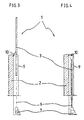
- FIG. 3 and 4 each show a cross section A-A as shown in FIG. 1, the same reference numerals also being used. This shows particularly clearly how the grating element 3 can be completely retracted behind the wall base 2.
- the gap to the sheet metal cladding 9 can be closed at the top with a cover flap 10, which closes automatically when the grid element 3 is retracted.
- the grating elements 3 are extended upward via the electric motor 7 and the spindle lifting elements 6 driven thereby, as is shown in FIG. 3 and FIG. 1.
- the grid elements 3 are releasably connected to each other by means of the locking elements 8, so that the fence system 1 receives sufficient overall stability.
- the grid elements 3 can be moved in and out at short notice.
- the extract can be specified as desired via the screw jack 6.
Landscapes
- Engineering & Computer Science (AREA)
- Architecture (AREA)
- Civil Engineering (AREA)
- Structural Engineering (AREA)
- Fencing (AREA)
- Cultivation Of Seaweed (AREA)
Applications Claiming Priority (2)
| Application Number | Priority Date | Filing Date | Title |
|---|---|---|---|
| DE29807218U DE29807218U1 (de) | 1998-04-21 | 1998-04-21 | Zaunanlage |
| DE29807218U | 1998-04-21 |
Publications (2)
| Publication Number | Publication Date |
|---|---|
| EP0952281A2 true EP0952281A2 (fr) | 1999-10-27 |
| EP0952281A3 EP0952281A3 (fr) | 2001-07-04 |
Family
ID=8056085
Family Applications (1)
| Application Number | Title | Priority Date | Filing Date |
|---|---|---|---|
| EP99107824A Withdrawn EP0952281A3 (fr) | 1998-04-21 | 1999-04-20 | Dispositif de clôture |
Country Status (2)
| Country | Link |
|---|---|
| EP (1) | EP0952281A3 (fr) |
| DE (1) | DE29807218U1 (fr) |
Cited By (9)
| Publication number | Priority date | Publication date | Assignee | Title |
|---|---|---|---|---|
| NL1018508C2 (nl) * | 2001-07-11 | 2003-01-21 | Steenhandel Noord Nederland V | Afscheiding met beweegbare schermelementen. |
| EP1452671A1 (fr) * | 2003-02-27 | 2004-09-01 | Star Progetti Tecnologie Applicate Srl | Elément d'écran |
| WO2007045700A1 (fr) * | 2005-10-19 | 2007-04-26 | Autocares Roncero, S.L. | Rampe escamotable et utilisation associee dans des plates-formes d'acces a des vehicules pour personnes handicapees |
| FR2909691A1 (fr) * | 2006-12-11 | 2008-06-13 | Eurovia Sa | Balise avec structure de protection escamotable |
| WO2010106371A1 (fr) * | 2009-03-19 | 2010-09-23 | Slick Systems (Uk) Limited | Barrière de sécurité |
| DE202010013836U1 (de) | 2010-10-04 | 2010-12-30 | Heintzmann Sicherheitssysteme Gmbh & Co. Kg | Objektschutzvorrichtung |
| DE202010013835U1 (de) | 2010-10-04 | 2010-12-30 | Heintzmann Sicherheitssysteme Gmbh & Co. Kg | Im Boden versenkbare Objektschutzvorrichtung |
| EP2436841A2 (fr) | 2010-10-04 | 2012-04-04 | Heintzmann Sicherheitssysteme GmbH & Co. KG | Dispositif de protection d'objet abaissable au sol |
| GB2510881A (en) * | 2013-02-18 | 2014-08-20 | Ischebeck Titan Ltd | Safety screen |
Families Citing this family (4)
| Publication number | Priority date | Publication date | Assignee | Title |
|---|---|---|---|---|
| SE535163C2 (sv) * | 2009-09-29 | 2012-05-02 | Svalson Ab | Balkongräcke med integrerat vindskydd |
| DE102010020467A1 (de) | 2010-05-10 | 2011-11-10 | Keller Andreas | unterfahrbares Zaunsystem |
| EP2775057A1 (fr) | 2013-03-07 | 2014-09-10 | Ergosafe AB | Section de barrière et barrière comprenant la section de barrière |
| DE102020001133A1 (de) | 2020-02-20 | 2021-08-26 | 2P Gmbh Sicherungstechnik Im Bahnbau | Gleissicherungseinrichtung |
Family Cites Families (2)
| Publication number | Priority date | Publication date | Assignee | Title |
|---|---|---|---|---|
| US2805046A (en) * | 1956-02-10 | 1957-09-03 | John C Petterson | Collapsible guard fence |
| DE29621995U1 (de) * | 1996-12-19 | 1997-02-13 | Verschleiß- und Korrosionsschutz Dr. Dörnemann GmbH & Co., 38259 Salzgitter | Absperrvorrichtung mit einem Zaun |
-
1998
- 1998-04-21 DE DE29807218U patent/DE29807218U1/de not_active Expired - Lifetime
-
1999
- 1999-04-20 EP EP99107824A patent/EP0952281A3/fr not_active Withdrawn
Cited By (13)
| Publication number | Priority date | Publication date | Assignee | Title |
|---|---|---|---|---|
| NL1018508C2 (nl) * | 2001-07-11 | 2003-01-21 | Steenhandel Noord Nederland V | Afscheiding met beweegbare schermelementen. |
| EP1452671A1 (fr) * | 2003-02-27 | 2004-09-01 | Star Progetti Tecnologie Applicate Srl | Elément d'écran |
| WO2007045700A1 (fr) * | 2005-10-19 | 2007-04-26 | Autocares Roncero, S.L. | Rampe escamotable et utilisation associee dans des plates-formes d'acces a des vehicules pour personnes handicapees |
| FR2909691A1 (fr) * | 2006-12-11 | 2008-06-13 | Eurovia Sa | Balise avec structure de protection escamotable |
| EP1936036A1 (fr) * | 2006-12-11 | 2008-06-25 | Eurovia | Balise avec structure de protection escamotable |
| WO2010106371A1 (fr) * | 2009-03-19 | 2010-09-23 | Slick Systems (Uk) Limited | Barrière de sécurité |
| DE202010013836U1 (de) | 2010-10-04 | 2010-12-30 | Heintzmann Sicherheitssysteme Gmbh & Co. Kg | Objektschutzvorrichtung |
| DE202010013835U1 (de) | 2010-10-04 | 2010-12-30 | Heintzmann Sicherheitssysteme Gmbh & Co. Kg | Im Boden versenkbare Objektschutzvorrichtung |
| EP2436841A2 (fr) | 2010-10-04 | 2012-04-04 | Heintzmann Sicherheitssysteme GmbH & Co. KG | Dispositif de protection d'objet abaissable au sol |
| GB2510881A (en) * | 2013-02-18 | 2014-08-20 | Ischebeck Titan Ltd | Safety screen |
| GB2510881B (en) * | 2013-02-18 | 2015-09-23 | Ischebeck Titan Ltd | Safety screen |
| GB2525795A (en) * | 2013-02-18 | 2015-11-04 | Ischebeck Titan Ltd | Safety screen |
| GB2525795B (en) * | 2013-02-18 | 2020-07-22 | Ischebeck Titan Ltd | Safety screen |
Also Published As
| Publication number | Publication date |
|---|---|
| DE29807218U1 (de) | 1998-08-20 |
| EP0952281A3 (fr) | 2001-07-04 |
Similar Documents
| Publication | Publication Date | Title |
|---|---|---|
| DE69519764T2 (de) | Jalousierbarer Rolladen | |
| DE69634208T2 (de) | Multifunktionnelles gebäude | |
| EP0952281A2 (fr) | Dispositif de clÔture | |
| DE2416274A1 (de) | Schutzvorrichtung fuer elektrische schalttafeln betreffend das ein- und ausschalten von elektrischen schaltern | |
| DE102018211798A1 (de) | Mobiles Zaunsystem zum Sichern einer Maschinenumgebung | |
| DE102009007877B4 (de) | Klappsitz für eine Steh- und Sitzplatztribüne | |
| EP2189189A1 (fr) | Trampoline | |
| DE3873390T2 (de) | Entlueftung einer transformatorenstation. | |
| DE60128182T2 (de) | Umzäunung, insbesondere zur Einbruchverhütung | |
| DE3824142A1 (de) | Transportables zelt | |
| DE29621995U1 (de) | Absperrvorrichtung mit einem Zaun | |
| DE8914394U1 (de) | Rolladenkasten für zwei nebeneinander laufende Rolläden | |
| DE3014523A1 (de) | Bausatz fuer eine umzaeunung | |
| EP0936339B1 (fr) | Grille à rouleau ou porte à rouleau avec porte enroulable | |
| AT515622A2 (de) | Überdachung, insbesondere für ein Schwimmbad | |
| DE4206343A1 (de) | Bausatz einer sonnenschutzeinrichtung zum einbau in oder an pergolas (pergolen) | |
| DE102009005533A1 (de) | Spielfeldbegrenzung für ein Kleinspielfeld | |
| EP4046546B1 (fr) | Lit, en particulier pour enfants, doté d'une construction de type maison | |
| DE2926780A1 (de) | Schalungssystem mit rechteckigen tafeln | |
| EP2901850A2 (fr) | Couverture stratiforme déplaçable | |
| DE60222382T2 (de) | Einrichtung zur abdeckung vom räumen | |
| DE202015101299U1 (de) | Schrankengelenkvorrichtung | |
| DE102011084318B4 (de) | Kletterstangenanlage | |
| DE6911916U (de) | Tor mit mechanisch heb- und senkbarem torblatt | |
| AT3921U1 (de) | Mehrzweckschutzumzäunung, insbesondere zur absicherung von strassenbaustellen und zum schutz der fahrbahn gegen wind und schneeverwehung |
Legal Events
| Date | Code | Title | Description |
|---|---|---|---|
| PUAI | Public reference made under article 153(3) epc to a published international application that has entered the european phase |
Free format text: ORIGINAL CODE: 0009012 |
|
| AK | Designated contracting states |
Kind code of ref document: A2 Designated state(s): BE DE ES FR GB IT NL |
|
| AX | Request for extension of the european patent |
Free format text: AL;LT;LV;MK;RO;SI |
|
| PUAL | Search report despatched |
Free format text: ORIGINAL CODE: 0009013 |
|
| AK | Designated contracting states |
Kind code of ref document: A3 Designated state(s): AT BE CH CY DE DK ES FI FR GB GR IE IT LI LU MC NL PT SE |
|
| AX | Request for extension of the european patent |
Free format text: AL;LT;LV;MK;RO;SI |
|
| RIC1 | Information provided on ipc code assigned before grant |
Free format text: 7E 04H 17/16 A, 7A 63C 19/00 B, 7E 04H 17/00 B, 7E 01F 13/04 B, 7A 63C 19/06 B |
|
| 17P | Request for examination filed |
Effective date: 20020103 |
|
| AKX | Designation fees paid |
Free format text: BE DE ES FR GB IT NL |
|
| 17Q | First examination report despatched |
Effective date: 20030909 |
|
| 18D | Application deemed to be withdrawn |
Effective date: 20040120 |
|
| 19U | Interruption of proceedings before grant |
Effective date: 20040101 |
|
| 19W | Proceedings resumed before grant after interruption of proceedings |
Effective date: 20050301 |
|
| STAA | Information on the status of an ep patent application or granted ep patent |
Free format text: STATUS: THE APPLICATION IS DEEMED TO BE WITHDRAWN |
|
| R18D | Application deemed to be withdrawn (corrected) |
Effective date: 20040120 |