EP0952374A2 - Amortisseur de vibrations torsionelles et son procédé de fabrication - Google Patents
Amortisseur de vibrations torsionelles et son procédé de fabrication Download PDFInfo
- Publication number
- EP0952374A2 EP0952374A2 EP99105882A EP99105882A EP0952374A2 EP 0952374 A2 EP0952374 A2 EP 0952374A2 EP 99105882 A EP99105882 A EP 99105882A EP 99105882 A EP99105882 A EP 99105882A EP 0952374 A2 EP0952374 A2 EP 0952374A2
- Authority
- EP
- European Patent Office
- Prior art keywords
- mass
- torsional vibration
- vibration damper
- primary
- damper according
- Prior art date
- Legal status (The legal status is an assumption and is not a legal conclusion. Google has not performed a legal analysis and makes no representation as to the accuracy of the status listed.)
- Granted
Links
Images





Classifications
-
- F—MECHANICAL ENGINEERING; LIGHTING; HEATING; WEAPONS; BLASTING
- F16—ENGINEERING ELEMENTS AND UNITS; GENERAL MEASURES FOR PRODUCING AND MAINTAINING EFFECTIVE FUNCTIONING OF MACHINES OR INSTALLATIONS; THERMAL INSULATION IN GENERAL
- F16F—SPRINGS; SHOCK-ABSORBERS; MEANS FOR DAMPING VIBRATION
- F16F15/00—Suppression of vibrations in systems; Means or arrangements for avoiding or reducing out-of-balance forces, e.g. due to motion
- F16F15/10—Suppression of vibrations in rotating systems by making use of members moving with the system
- F16F15/12—Suppression of vibrations in rotating systems by making use of members moving with the system using elastic members or friction-damping members, e.g. between a rotating shaft and a gyratory mass mounted thereon
- F16F15/131—Suppression of vibrations in rotating systems by making use of members moving with the system using elastic members or friction-damping members, e.g. between a rotating shaft and a gyratory mass mounted thereon the rotating system comprising two or more gyratory masses
- F16F15/133—Suppression of vibrations in rotating systems by making use of members moving with the system using elastic members or friction-damping members, e.g. between a rotating shaft and a gyratory mass mounted thereon the rotating system comprising two or more gyratory masses using springs as elastic members, e.g. metallic springs
- F16F15/134—Wound springs
- F16F15/13415—Wound springs characterised by the dimension or shape of spring-containing windows
- F16F15/13423—Disposition of material for damping or avoiding wear
-
- F—MECHANICAL ENGINEERING; LIGHTING; HEATING; WEAPONS; BLASTING
- F16—ENGINEERING ELEMENTS AND UNITS; GENERAL MEASURES FOR PRODUCING AND MAINTAINING EFFECTIVE FUNCTIONING OF MACHINES OR INSTALLATIONS; THERMAL INSULATION IN GENERAL
- F16F—SPRINGS; SHOCK-ABSORBERS; MEANS FOR DAMPING VIBRATION
- F16F15/00—Suppression of vibrations in systems; Means or arrangements for avoiding or reducing out-of-balance forces, e.g. due to motion
- F16F15/10—Suppression of vibrations in rotating systems by making use of members moving with the system
- F16F15/12—Suppression of vibrations in rotating systems by making use of members moving with the system using elastic members or friction-damping members, e.g. between a rotating shaft and a gyratory mass mounted thereon
- F16F15/131—Suppression of vibrations in rotating systems by making use of members moving with the system using elastic members or friction-damping members, e.g. between a rotating shaft and a gyratory mass mounted thereon the rotating system comprising two or more gyratory masses
-
- F—MECHANICAL ENGINEERING; LIGHTING; HEATING; WEAPONS; BLASTING
- F16—ENGINEERING ELEMENTS AND UNITS; GENERAL MEASURES FOR PRODUCING AND MAINTAINING EFFECTIVE FUNCTIONING OF MACHINES OR INSTALLATIONS; THERMAL INSULATION IN GENERAL
- F16F—SPRINGS; SHOCK-ABSORBERS; MEANS FOR DAMPING VIBRATION
- F16F15/00—Suppression of vibrations in systems; Means or arrangements for avoiding or reducing out-of-balance forces, e.g. due to motion
- F16F15/10—Suppression of vibrations in rotating systems by making use of members moving with the system
- F16F15/12—Suppression of vibrations in rotating systems by making use of members moving with the system using elastic members or friction-damping members, e.g. between a rotating shaft and a gyratory mass mounted thereon
- F16F15/131—Suppression of vibrations in rotating systems by making use of members moving with the system using elastic members or friction-damping members, e.g. between a rotating shaft and a gyratory mass mounted thereon the rotating system comprising two or more gyratory masses
- F16F15/13114—Suppression of vibrations in rotating systems by making use of members moving with the system using elastic members or friction-damping members, e.g. between a rotating shaft and a gyratory mass mounted thereon the rotating system comprising two or more gyratory masses characterised by modifications for auxiliary purposes, e.g. provision of a timing mark
-
- F—MECHANICAL ENGINEERING; LIGHTING; HEATING; WEAPONS; BLASTING
- F16—ENGINEERING ELEMENTS AND UNITS; GENERAL MEASURES FOR PRODUCING AND MAINTAINING EFFECTIVE FUNCTIONING OF MACHINES OR INSTALLATIONS; THERMAL INSULATION IN GENERAL
- F16F—SPRINGS; SHOCK-ABSORBERS; MEANS FOR DAMPING VIBRATION
- F16F15/00—Suppression of vibrations in systems; Means or arrangements for avoiding or reducing out-of-balance forces, e.g. due to motion
- F16F15/10—Suppression of vibrations in rotating systems by making use of members moving with the system
- F16F15/12—Suppression of vibrations in rotating systems by making use of members moving with the system using elastic members or friction-damping members, e.g. between a rotating shaft and a gyratory mass mounted thereon
- F16F15/131—Suppression of vibrations in rotating systems by making use of members moving with the system using elastic members or friction-damping members, e.g. between a rotating shaft and a gyratory mass mounted thereon the rotating system comprising two or more gyratory masses
- F16F15/13142—Suppression of vibrations in rotating systems by making use of members moving with the system using elastic members or friction-damping members, e.g. between a rotating shaft and a gyratory mass mounted thereon the rotating system comprising two or more gyratory masses characterised by the method of assembly, production or treatment
- F16F15/1315—Multi-part primary or secondary masses, e.g. assembled from pieces of sheet steel
-
- F—MECHANICAL ENGINEERING; LIGHTING; HEATING; WEAPONS; BLASTING
- F16—ENGINEERING ELEMENTS AND UNITS; GENERAL MEASURES FOR PRODUCING AND MAINTAINING EFFECTIVE FUNCTIONING OF MACHINES OR INSTALLATIONS; THERMAL INSULATION IN GENERAL
- F16F—SPRINGS; SHOCK-ABSORBERS; MEANS FOR DAMPING VIBRATION
- F16F15/00—Suppression of vibrations in systems; Means or arrangements for avoiding or reducing out-of-balance forces, e.g. due to motion
- F16F15/10—Suppression of vibrations in rotating systems by making use of members moving with the system
- F16F15/12—Suppression of vibrations in rotating systems by making use of members moving with the system using elastic members or friction-damping members, e.g. between a rotating shaft and a gyratory mass mounted thereon
- F16F15/131—Suppression of vibrations in rotating systems by making use of members moving with the system using elastic members or friction-damping members, e.g. between a rotating shaft and a gyratory mass mounted thereon the rotating system comprising two or more gyratory masses
- F16F15/13164—Suppression of vibrations in rotating systems by making use of members moving with the system using elastic members or friction-damping members, e.g. between a rotating shaft and a gyratory mass mounted thereon the rotating system comprising two or more gyratory masses characterised by the supporting arrangement of the damper unit
- F16F15/13171—Bearing arrangements
- F16F15/13178—Bearing arrangements comprising slide bearings
-
- F—MECHANICAL ENGINEERING; LIGHTING; HEATING; WEAPONS; BLASTING
- F16—ENGINEERING ELEMENTS AND UNITS; GENERAL MEASURES FOR PRODUCING AND MAINTAINING EFFECTIVE FUNCTIONING OF MACHINES OR INSTALLATIONS; THERMAL INSULATION IN GENERAL
- F16F—SPRINGS; SHOCK-ABSORBERS; MEANS FOR DAMPING VIBRATION
- F16F15/00—Suppression of vibrations in systems; Means or arrangements for avoiding or reducing out-of-balance forces, e.g. due to motion
- F16F15/10—Suppression of vibrations in rotating systems by making use of members moving with the system
- F16F15/12—Suppression of vibrations in rotating systems by making use of members moving with the system using elastic members or friction-damping members, e.g. between a rotating shaft and a gyratory mass mounted thereon
- F16F15/131—Suppression of vibrations in rotating systems by making use of members moving with the system using elastic members or friction-damping members, e.g. between a rotating shaft and a gyratory mass mounted thereon the rotating system comprising two or more gyratory masses
- F16F15/133—Suppression of vibrations in rotating systems by making use of members moving with the system using elastic members or friction-damping members, e.g. between a rotating shaft and a gyratory mass mounted thereon the rotating system comprising two or more gyratory masses using springs as elastic members, e.g. metallic springs
- F16F15/134—Wound springs
- F16F15/1343—Wound springs characterised by the spring mounting
-
- F—MECHANICAL ENGINEERING; LIGHTING; HEATING; WEAPONS; BLASTING
- F16—ENGINEERING ELEMENTS AND UNITS; GENERAL MEASURES FOR PRODUCING AND MAINTAINING EFFECTIVE FUNCTIONING OF MACHINES OR INSTALLATIONS; THERMAL INSULATION IN GENERAL
- F16F—SPRINGS; SHOCK-ABSORBERS; MEANS FOR DAMPING VIBRATION
- F16F15/00—Suppression of vibrations in systems; Means or arrangements for avoiding or reducing out-of-balance forces, e.g. due to motion
- F16F15/10—Suppression of vibrations in rotating systems by making use of members moving with the system
- F16F15/12—Suppression of vibrations in rotating systems by making use of members moving with the system using elastic members or friction-damping members, e.g. between a rotating shaft and a gyratory mass mounted thereon
- F16F15/131—Suppression of vibrations in rotating systems by making use of members moving with the system using elastic members or friction-damping members, e.g. between a rotating shaft and a gyratory mass mounted thereon the rotating system comprising two or more gyratory masses
- F16F15/133—Suppression of vibrations in rotating systems by making use of members moving with the system using elastic members or friction-damping members, e.g. between a rotating shaft and a gyratory mass mounted thereon the rotating system comprising two or more gyratory masses using springs as elastic members, e.g. metallic springs
- F16F15/134—Wound springs
- F16F15/13469—Combinations of dampers, e.g. with multiple plates, multiple spring sets, i.e. complex configurations
- F16F15/13476—Combinations of dampers, e.g. with multiple plates, multiple spring sets, i.e. complex configurations resulting in a staged spring characteristic, e.g. with multiple intermediate plates
- F16F15/13484—Combinations of dampers, e.g. with multiple plates, multiple spring sets, i.e. complex configurations resulting in a staged spring characteristic, e.g. with multiple intermediate plates acting on multiple sets of springs
-
- F—MECHANICAL ENGINEERING; LIGHTING; HEATING; WEAPONS; BLASTING
- F16—ENGINEERING ELEMENTS AND UNITS; GENERAL MEASURES FOR PRODUCING AND MAINTAINING EFFECTIVE FUNCTIONING OF MACHINES OR INSTALLATIONS; THERMAL INSULATION IN GENERAL
- F16F—SPRINGS; SHOCK-ABSORBERS; MEANS FOR DAMPING VIBRATION
- F16F2222/00—Special physical effects, e.g. nature of damping effects
- F16F2222/02—Special physical effects, e.g. nature of damping effects temperature-related
-
- F—MECHANICAL ENGINEERING; LIGHTING; HEATING; WEAPONS; BLASTING
- F16—ENGINEERING ELEMENTS AND UNITS; GENERAL MEASURES FOR PRODUCING AND MAINTAINING EFFECTIVE FUNCTIONING OF MACHINES OR INSTALLATIONS; THERMAL INSULATION IN GENERAL
- F16F—SPRINGS; SHOCK-ABSORBERS; MEANS FOR DAMPING VIBRATION
- F16F2222/00—Special physical effects, e.g. nature of damping effects
- F16F2222/04—Friction
-
- F—MECHANICAL ENGINEERING; LIGHTING; HEATING; WEAPONS; BLASTING
- F16—ENGINEERING ELEMENTS AND UNITS; GENERAL MEASURES FOR PRODUCING AND MAINTAINING EFFECTIVE FUNCTIONING OF MACHINES OR INSTALLATIONS; THERMAL INSULATION IN GENERAL
- F16F—SPRINGS; SHOCK-ABSORBERS; MEANS FOR DAMPING VIBRATION
- F16F2230/00—Purpose; Design features
- F16F2230/32—Modular design
Definitions
- the present invention relates to a torsional vibration damper with a primary mass and a secondary mass.
- the present invention also relates to a method for producing such a torsional vibration damper.
- Such torsional vibration dampers are often used in particular in connection with couplings.
- greater flexibility and adaptability of the torsional vibration damper to individual customer requirements should also be made possible.
- the present invention on the one hand proposes a torsional vibration damper with a primary mass and a secondary mass, in which the primary mass comprises a primary plate which transmits a torque from the primary mass to the secondary mass.
- the use of a sheet for torque transmission ensures that this assembly is easy to manufacture, since only the processing methods required for sheet metal need be used.
- the torque-transmitting function of the primary plate enables it to be used on other components such as bars, levers and the like. to waive the torque transmission.
- the primary plate can be shaped in such a way that it can take over the entire torque-transmitting function.
- the primary plate can have at least one support surface with a surface pointing perpendicular to the direction of rotation of the torsional vibration damper, which surface is formed by shaping the primary plate.
- Such a support surface allows forces to be transmitted in the circumferential direction starting from the primary plate. This can e.g. B. advantageously on a thrust piston and springs comprising spring arrangement, which is arranged between the primary and secondary mass, happen. This makes it possible to dispense with additional assemblies that provide such support surfaces.
- the primary plate is advantageously designed as an assembly symmetrical to the main axis of rotation of the torsional vibration damper. This can be rotational, axis, or mirror symmetry.
- Such an arrangement on the one hand increases the stability of the primary plate in itself and on the other hand ensures simple manufacture of the torsional vibration damper according to the invention, since on the one hand the risk of possible imbalances and their time-consuming elimination is minimized and on the other hand such a one-piece assembly is much easier on other assemblies, such as e.g. B. an additional mass, can be positioned and attached than would be the case with multi-part assemblies.
- the primary plate can have tangential friction surfaces, which can be arranged in particular between the shapes of the primary plate.
- tangential friction surfaces are understood to mean surface areas of the primary sheet which point in the circumferential direction in at least one component and which rub with a torque-absorbing assembly, such as, for. B. the thrust piston of a spring arrangement, in connection.
- the primary plate is able to transmit or absorb the entire torque starting from the primary mass.
- the thrust pistons can be formed from a full injection molding or a fiber-reinforced injection molding and / or can be provided with ribs.
- the torsional vibration damper according to the invention can be designed such that grease or similar lubricants in the area of the thrust piston can be dispensed with. In this way, existing sealing problems can be avoided.
- the primary sheet in order to enable the spaces formed by the tangential friction surfaces and the formations on the primary sheet to be sealed against the penetration of grease, the primary sheet can have a cylindrical attachment area.
- An assembly e.g. B. a sealing ring can be attached in a relatively uncomplicated manner.
- the cylindrical attachment area is designed as a flange.
- the assembly to be fastened e.g. B. the seal, simple - e.g. B. by clipping - be attached to the flange.
- such a flange enables further assemblies, such as. B. to stabilize an additional mass to be attached to the primary sheet in the axial direction, ie parallel to the main axis of rotation of the torsional vibration damper.
- the seal it may be necessary to the primary sheet in the cylindrical attachment area of a shaping aftertreatment, such as. B. to undergo machining.
- a shaping aftertreatment such as. B. to undergo machining.
- Such an aftertreatment, in which the primary sheet may have to be additionally clamped does not change the advantage of minimizing the number of components and a relatively easy manufacture that is made possible by the primary sheet.
- the primary sheet can be placed radially on the inside on a central flange or a shaft, e.g. B. the drive shaft of an engine. It may be necessary to carry out a shaping aftertreatment of a radially inner area of the primary sheet. Such an aftertreatment does not prevent the advantage according to the invention of using a primary sheet and can be limited to a necessary minimum.
- the present invention is not limited to the use of a sheet in the narrow sense. Rather, any sheet-like structure that has been brought into the desired shape by forming can serve as the primary sheet. It goes without saying that the primary sheet can also be subjected to further process steps, in particular machining or material-removing process steps.
- An angled area arranged essentially parallel to the main axis of rotation of the torsional vibration damper can be produced on the primary sheet in one forming step.
- Such angled areas serve on the one hand for immediate stabilization of the primary sheet.
- an additional mass can be brought to bear on these angled areas. This requires a relatively large contact area between the additional mass and the primary plate, which serves to further stabilize the torsional vibration damper.
- the side of the angled area facing away from the additional mass can moreover be used advantageously as a tangential friction surface for the torque transmission or damping. It is also possible to provide, in the angled area, radially inward-facing formations which serve as support surfaces. In this respect, the angled area for supporting the additional mass and the tangential friction surfaces and support surfaces for torque transmission and for damping can be provided in one work step.
- the additional mass can be shrunk onto the primary sheet and / or spot welded or spot welded to the primary sheet. This provides a stable, yet sufficiently elastic connection between the additional mass and the primary sheet in a simple manner.
- the aforementioned arrangement between additional mass and primary sheet ensures easy production of the same. Only the radially inner areas of the additional mass that come into contact with the primary sheet require a corresponding fit. The same applies to the radial outside of the angled areas of the primary plate.
- this arrangement enables the calibrating post-processing of both assemblies to be kept to a minimum, namely the aforementioned ranges, before they are assembled. Because of the inherent elasticity of the primary sheet and especially when the additional mass is shrunk onto the primary sheet, it may be possible to dispense entirely with post-processing.
- the additional mass can be a greeting part, preferably made of cast steel.
- the additional mass can also be produced from a section or flat steel that has been cut to length. Such a semifinished product is then bent and connected at its ends, preferably welded, in order to provide the essentially cylindrical additional mass. Such a manufacturing process for the additional mass is particularly suitable for large quantities.
- the additional mass can still be processed in a calibrating manner after the two ends of the bent profile or flat steel have been connected in order to facilitate connection to the primary sheet.
- this method step can include machining and / or cold pressing of the areas abutting the angled area of the primary sheet.
- a starter ring gear can be attached radially outside to the additional mass. It is preferably attached before the calibrating processing of the Additional mass, so that the assembly thus formed is calibrated in one step.
- the structural separation between the starter ring gear and additional mass enables, on the one hand, easier production of the overall arrangement and, on the other hand, greater variability in adapting to special customer requirements, e.g. B. in relation to the size of the torque or the radius of the starter ring gear.
- this structural separation can also advantageously be used independently of the other features of the torsional vibration damper according to the invention.
- the easiest way to balance the primary mass is through suitable milling or drilling into the additional mass.
- these millings or bores can be arranged in a radial surface area of the additional mass. This makes it particularly simple possible about the changes made during balancing, such as. B. the millings or holes to attach a cover plate. This can then be easily attached to the primary mass from one side, essentially in the form of a ring.
- balancing measures can also be carried out on other areas of the primary mass and can be covered by a cover plate in the manner according to the invention.
- a transmitter plate can be provided on the torsional vibration damper, which is attached to the primary mass of the torsional vibration damper.
- this ensures simple assembly of the overall arrangement.
- the overall arrangement can be adapted much more easily to individual customer requirements, since only signal transmitters on the transmitter plate have to be adapted to customer requirements.
- the transmitter plate also serves as a cover plate for measures caused by the balancing of the primary mass, such as milling and / or bores or additional masses attached.
- the transmitter plate preferably has holes as a signal transmitter. On the one hand, any protruding assemblies are thereby avoided. On the other hand, these holes have no adverse effect on the other components of the torsional vibration damper. In this way, they cannot lead to sealing problems and only have an insignificant influence on the balancing of the entire torsional vibration damper due to the small sheet thickness.
- the transmitter plate is preferably attached to at least one essentially radial surface of the primary mass. On the one hand, this ensures a relatively uncomplicated attachment, and on the other hand, no additional formations or attachment points need to be provided on the primary mass, since such radial surfaces are naturally present in rotating components which should not have an unnecessarily large axial extension.
- the transmitter plate can be attached both to a primary plate and to an additional mass of the primary mass.
- this ensures a secure fastening of the walking plate itself.
- the donor plate can serve in this way to fix the additional mass to the primary plate.
- Such an arrangement proves to be particularly advantageous when the additional mass is fixed in an axial direction by a flange of the primary plate.
- the fixation can be axial Direction through the encoder plate. This means that such an arrangement is easy to manufacture, since only the additional mass needs to be placed on the primary mass and then the additional mass is already fastened by attaching the transmitter plate to the primary mass.
- a torsional vibration damper In order to further facilitate the manufacture of a torsional vibration damper, it is proposed to provide radial recesses in the secondary mass. Such recesses advantageously increase the resistance of the secondary mass to heat. Since such torsional vibration dampers are often used in clutches and coupling processes release relatively high thermal energies, the secondary mass in particular is subject to a relatively high thermal load.
- the radial recesses according to the invention reduce the material stresses which occur under such a thermal load, so that the secondary mass can be made from a less heat-insensitive material. Such a material is generally much easier to process than high-strength and heat-resistant materials.
- incisions or depressions u. ⁇ . serve, which are suitable for reducing heat-related tensions. This applies in particular to material stresses which are caused by thermal energy applied from the inside radially.
- the present invention furthermore proposes a torsional vibration damper with a primary and a secondary mass, which are rotatably supported relative to one another by means of a sliding bearing, which comprises a sliding surface made of a polyamide, preferably made of PA 4.6 (Stanyl).
- a sliding bearing which comprises a sliding surface made of a polyamide, preferably made of PA 4.6 (Stanyl).
- this material can be varied and reinforced by additives, particularly with regard to its sliding properties.
- the temperature behavior of a torsional vibration damper with a primary mass and a secondary mass can furthermore be improved by a plain bearing between the primary and secondary masses with the bearing bush at least partially interrupted in the circumferential direction.
- the bearing bush can expand in the circumferential direction, as a result of which the bearing is subjected to less stress and the operating properties of the torsional vibration damper improve.
- An improved behavior under thermal stress also shows a torsional vibration damper with a primary mass and a secondary mass, which comprises a plain bearing between the primary and secondary mass with a longitudinally slotted bearing bush in the circumferential direction.
- this arrangement also has the advantage that the bearing bush consists of at least two sections arranged axially to one another and can accordingly be easily assembled from different axial sides on an assembly which is enclosed by the bearing bush.
- the slide bearing can comprise a slide ring with an essentially L-shaped cross section.
- a bearing bush can be assembled relatively easily since it only has to be inserted into a corresponding groove.
- This slide ring can also be composed of a slide bush with an essentially cylindrical cross section and an essentially radially oriented slide disk. On the one hand, this enables greater freedom of the slide ring in the event of thermal expansion and, on the other hand, greater variability in the design of the slide bearing, since the slide bush and slide washer can be selected from different materials depending on requirements.
- the slide ring with an essentially L-shaped cross section ensures a sliding bearing in the radial direction and one axial direction. If this is not sufficient, e.g. B. a second slide ring with a substantially L-shaped cross section may be provided, which is arranged opposite the first slide ring in such a way that a bearing bush with a substantially U-shaped cross section is formed.
- the use of two identical slide rings enables a relatively inexpensive bearing between the primary and secondary mass to be slid in both radial and both axial directions.
- an im substantially radially arranged sliding washer is provided, which is arranged such that an essentially U-shaped bearing bush is formed. This also ensures a sliding bearing both in the radial direction and in both axial directions.
- the sliding washer can be made of a different material than the sliding ring and can thus be suitably and inexpensively adapted to the stresses occurring at this point.
- the thrust piston spring arrangement can comprise at least two shear piston spring devices which have different spring damping characteristics.
- the spring-damping behavior of such a torsional vibration damper is usually dominated by one of the two thrust piston spring devices in such an arrangement, while the properties of the second thrust piston spring device predominantly apply to larger torsion angles or torques come. This enables greater variability in adapting to special customer requests.
- the two push piston spring devices can be connected in parallel or in series between the primary mass and the secondary mass.
- this can be made possible in particular by an intermediate assembly which interacts with the first thrust piston spring device on the one hand and with the second thrust piston spring device on the other hand the first thrust piston spring device in turn interact with the primary mass and the second thrust piston spring device in turn with the secondary mass.
- At least one stop can be provided which prevents compression of one of the thrust piston spring devices beyond a certain angle of rotation.
- This relates in particular to the thrust piston spring device which responds to lower torques and in which unnecessary overloading is avoided in this way.
- the effect of this thrust piston spring device can be switched off from a certain angle of rotation in this way.
- the attack can e.g. B. between the primary or secondary mass and the intermediate assembly.
- a stop can be attached to any position of the torsional vibration damper, as long as it prevents compression of the corresponding thrust piston spring device beyond a certain angle of rotation in the desired manner.
- a torsional vibration damper in such a way that no grease is required in the rooms in which the springs - and thus also the thrust pistons - are arranged.
- This can be done in particular by selecting the materials for the thrust pistons and for the surfaces that come into contact with the thrust pistons in a suitable manner.
- the effective angle between the push piston and these surfaces can also be designed accordingly. While angles of attack between 4 and 6 ° are currently used, this angle can be selected to be over 10 °.
- angle of attack denotes the effective wedge angle of the thrust piston between the two surfaces of the driving and / or driving assemblies acting on it.
- the thrust pistons can be made of plastic.
- inner ribs or the like can be provided in the thrust piston, so that these unnecessary material tensions are not unexposed.
- other designs of the thrust pistons are also possible in order to avoid that they are present as solid bodies and are therefore exposed to internal material stresses.
- the present invention provides a novel torsional vibration damper, in which the inventive basic idea is realized, by specializing the tasks of the individual assemblies, to ensure a simpler and more cost-effective production of a torsional vibration damper with constant or even improved quality.
- the invention provides a torsional vibration damper in which a primary plate is used to transmit torque to a secondary mass, an additional mass ensures a sufficient moment of inertia, a separate starter ring gear and a transmitter plate are provided as separate signaling devices, the secondary mass and its storage have a direct connection to a heat-generating coupling enables and this bearing can be adapted to existing requirements with great variability. It is understood here that the invention is not limited to the designation Assemblies as primary or secondary mass is limited, but that their basic ideas can be advantageously used both in driving and in aborting assemblies of torsional vibration dampers.
- the torsional vibration damper comprises a primary plate 1, which is firmly connected to an additional mass 2, and a secondary mass 3, which is rotatably mounted on the primary plate 1.
- the storage takes place in a U-shaped groove, which is formed by an essentially Z-shaped central flange 9 and the primary plate 1.
- Central flange 9 and primary plate 1 are fixed to one another by tubular rivets 10 (numbered as an example).
- the primary plate 1 and the central flange 9 have bores 12 (exemplarily numbered) which are used for fastening to a shaft penetrating the central flange in a central opening 13.
- the primary plate 1 has an angled region 6 (see in particular FIG. 2), on which the additional mass 2 is applied radially on the outside.
- the radially inner side of the angled regions 6 form tangential friction surfaces 60 (numbered by way of example), which are interrupted by shapes 5 (numbered by way of example) of the primary plate 1.
- These formations 5 have surfaces which are perpendicular to the direction of rotation of the torsional vibration damper and serve as support surfaces 50 for thrust pistons 17 (numbered by way of example).
- Springs 18 (numbered as an example) are arranged between two push pistons 17.
- the angled areas 6 together with the formations 5 and the wall of the secondary mass 2 form spring chambers 21 (numbered as an example) which are filled with silicone grease.
- a seal 4 is used to seal the spring chambers, which is clipped onto a flange 40 of the primary plate 1 and in this case encompasses its cylindrical attachment region.
- the primary plate 1 thus transmits a torque to the secondary mass 2 via the tangential friction surfaces 60 and the formations 5. Furthermore, the primary plate 1 has lugs 11 (see FIG. 2), on which, for example, a friction ring or the like can be provided for additional damping. As can be seen in particular on the basis of these lugs 11 and the formations 5, the choice of a sheet-like base body is outstandingly suitable for producing an assembly which is used for torque transmission or damping in the case of torsional vibration dampers.
- the additional mass 2 is on the primary plate 1, in particular on the angled area 6 of the primary plate 1, shrunk on and indirectly fixed by spot welding.
- the additional mass 2 is fixed directly via a transmitter plate 16, which in turn is connected to the primary plate via spot welds 14. As can be seen in particular from FIG. 2, the additional mass is thus fixed in addition to the frictional engagement caused by the shrinking on by the flange 40 of the primary plate 1 and the transmitter plate 16.
- the transmitter plate 16 is fastened to an essentially radial surface of the primary mass 1.
- the transmitter plate is supported on a radial surface of the additional mass 2.
- it covers bores 20 (numbered as an example) which are located in the additional mass 2 and serve to balance the primary mass. Instead of the bore 20, it is also possible to provide millings which have less or no notch effect.
- the transmitter plate 16 has bores 16 'which serve as signal transmitters for a bearing-dependent motor control.
- the primary sheet 1 is produced by cold working, as is the central flange 9.
- the additional mass 2 is produced from a section steel with the cross section shown in FIG. Here, a correspondingly cut-to-length part is bent and welded at its ends. The welds are then made on the inside and in the area of the installation of a starter ring gear 15 in a calibrating work step away. In a next step, the additional mass 2 is heated so that it expands and is placed with its essentially cylindrical inner surface area on the angled area 6 of the primary plate 1 in contact with the flange 40. When cooling, the additional mass 2 shrinks and enters into a frictional engagement with the primary sheet 1. The starter ring gear 15 is then attached and the primary mass thus provided is balanced.
- the transmitter plate 16 is spot welded to the primary plate 1.
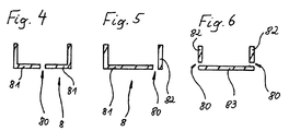
- a bearing bush 8 arranged in it has an essentially U-shaped cross section (see FIG. 4). On the one hand, it is interrupted in the circumferential direction at the point designated by 7 (see FIG. 1). It also has a longitudinal slot 80 in the circumferential direction (see FIG. 4) and thus comprises two sliding rings 81 with an essentially L-shaped cross section. On the one hand, this ensures that the bearing can be assembled relatively easily by arranging the two sliding rings 81 on both sides of the secondary mass 3. On the other hand, there is the possibility that the bearing bush 8 can expand when heated.
- Both slide rings 81 consist of slip-modified stanyl.
- FIG. 5 has only one slide ring 81.
- a sliding disk 82 is indicative of the clutch (on the right in the drawing) provided, which consists of a non-slip modified stanyl.
- this bearing bush 8 can be produced relatively inexpensively by taking into account the lower load on the bearing bush 8 on the coupling side.
- the sliding plate 82 can also be dispensed with entirely.
- the slide ring 81 of the embodiment shown in FIG. 5 can also be replaced by a slide bush 83 and a further slide washer 82, as shown in FIG. This results in an even greater scope in the choice of materials. Furthermore, the possibilities of thermal expansion are greater in this embodiment.
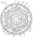
- the torsional vibration damper shown in FIGS. 7 to 9 has a first thrust piston spring device which comprises thrust pistons 17 'which are arranged in spring chambers 21' of the primary plate 1.
- This first thrust piston spring device in turn interacts with an intermediate assembly 90, specifically in this embodiment with an outer circumferential surface 91 of this intermediate assembly 90.
- the intermediate assembly 90 in turn has spring chambers 21 ′′, in which further thrust pistons 17 ′′ are arranged, which together with corresponding springs form a second thrust piston spring device.
- This thrust piston spring device in turn interacts with the secondary mass 3, in this exemplary embodiment also with a circumferential surface running in the circumferential direction.
- the intermediate assembly 90 further comprises recesses 92 (numbered by way of example) into which lugs 35 (numbered by way of example) of the secondary mass 3 engage.
- the lugs 34 come into contact with the edge of the recesses 92 at a certain angle of rotation, as a result of which a stop is formed which prevents compression of the second thrust piston spring device beyond this specific angle of rotation.
- a torsional vibration damper is created, the spring-damping characteristic of which is controlled by the first thrust piston spring device at angles of rotation which are above the determined angle of rotation.
- the behavior of the torsional vibration damper at angles of rotation at this specific angle of rotation is predominantly controlled by the second, more compressing thrust piston spring device.
- FIG. 10 shows a secondary mass variant 3 a which can be used both in the first and in the second embodiment and has radial recesses 30. Through these recesses are thermal Material stresses reduced in such a way that the secondary mass 3a can be produced relatively cheaply from gray cast iron.
Landscapes
- Engineering & Computer Science (AREA)
- General Engineering & Computer Science (AREA)
- Physics & Mathematics (AREA)
- Acoustics & Sound (AREA)
- Aviation & Aerospace Engineering (AREA)
- Mechanical Engineering (AREA)
- Manufacturing & Machinery (AREA)
- Mechanical Operated Clutches (AREA)
- Support Of The Bearing (AREA)
- Buildings Adapted To Withstand Abnormal External Influences (AREA)
- Surgical Instruments (AREA)
- Vibration Prevention Devices (AREA)
- Connection Of Motors, Electrical Generators, Mechanical Devices, And The Like (AREA)
- Pressure Welding/Diffusion-Bonding (AREA)
- Pulleys (AREA)
- Sliding-Contact Bearings (AREA)
Priority Applications (3)
| Application Number | Priority Date | Filing Date | Title |
|---|---|---|---|
| EP01105519A EP1111269B1 (fr) | 1998-04-22 | 1999-03-24 | Amortisseur de vibrations torsionelles |
| EP07011954A EP1837550B1 (fr) | 1998-04-22 | 1999-03-24 | Amortisseur de vibrations de torsion |
| EP07010954A EP1820998B1 (fr) | 1998-04-22 | 1999-03-24 | Amortisseur de vibrations torsionnelles et procédure de fabrication d'un tel |
Applications Claiming Priority (2)
| Application Number | Priority Date | Filing Date | Title |
|---|---|---|---|
| DE19817910.3A DE19817910B4 (de) | 1998-04-22 | 1998-04-22 | Torsionsschwingungsdämpfer und Verfahren zu dessen Herstellung |
| DE19817910 | 1998-04-22 |
Related Child Applications (3)
| Application Number | Title | Priority Date | Filing Date |
|---|---|---|---|
| EP01105519A Division EP1111269B1 (fr) | 1998-04-22 | 1999-03-24 | Amortisseur de vibrations torsionelles |
| EP07010954A Division EP1820998B1 (fr) | 1998-04-22 | 1999-03-24 | Amortisseur de vibrations torsionnelles et procédure de fabrication d'un tel |
| EP07011954A Division EP1837550B1 (fr) | 1998-04-22 | 1999-03-24 | Amortisseur de vibrations de torsion |
Publications (3)
| Publication Number | Publication Date |
|---|---|
| EP0952374A2 true EP0952374A2 (fr) | 1999-10-27 |
| EP0952374A3 EP0952374A3 (fr) | 2004-01-02 |
| EP0952374B1 EP0952374B1 (fr) | 2007-12-26 |
Family
ID=7865394
Family Applications (4)
| Application Number | Title | Priority Date | Filing Date |
|---|---|---|---|
| EP07011954A Revoked EP1837550B1 (fr) | 1998-04-22 | 1999-03-24 | Amortisseur de vibrations de torsion |
| EP01105519A Expired - Lifetime EP1111269B1 (fr) | 1998-04-22 | 1999-03-24 | Amortisseur de vibrations torsionelles |
| EP99105882A Revoked EP0952374B1 (fr) | 1998-04-22 | 1999-03-24 | Amortisseur de vibrations torsionelles et son procédé de fabrication |
| EP07010954A Expired - Lifetime EP1820998B1 (fr) | 1998-04-22 | 1999-03-24 | Amortisseur de vibrations torsionnelles et procédure de fabrication d'un tel |
Family Applications Before (2)
| Application Number | Title | Priority Date | Filing Date |
|---|---|---|---|
| EP07011954A Revoked EP1837550B1 (fr) | 1998-04-22 | 1999-03-24 | Amortisseur de vibrations de torsion |
| EP01105519A Expired - Lifetime EP1111269B1 (fr) | 1998-04-22 | 1999-03-24 | Amortisseur de vibrations torsionelles |
Family Applications After (1)
| Application Number | Title | Priority Date | Filing Date |
|---|---|---|---|
| EP07010954A Expired - Lifetime EP1820998B1 (fr) | 1998-04-22 | 1999-03-24 | Amortisseur de vibrations torsionnelles et procédure de fabrication d'un tel |
Country Status (6)
| Country | Link |
|---|---|
| US (1) | US6364775B1 (fr) |
| EP (4) | EP1837550B1 (fr) |
| JP (1) | JP2000002299A (fr) |
| AT (1) | ATE298849T1 (fr) |
| DE (5) | DE19817910B4 (fr) |
| ES (3) | ES2299225T3 (fr) |
Cited By (6)
| Publication number | Priority date | Publication date | Assignee | Title |
|---|---|---|---|---|
| FR2785651A1 (fr) * | 1998-11-05 | 2000-05-12 | Luk Lamellen & Kupplungsbau | Composant d'assemblage avec un vilebrequin et procede de fabrication correspondant |
| WO2001011258A1 (fr) * | 1999-08-10 | 2001-02-15 | Ap Tmf Limited | Volants a masses jumelees |
| EP1862696A1 (fr) * | 2006-05-29 | 2007-12-05 | Nissan Motor Co., Ltd. | Volant d'inertie |
| WO2016141930A1 (fr) * | 2015-03-11 | 2016-09-15 | Schaeffler Technologies AG & Co. KG | Dispositif de transmission de couple |
| FR3085063A1 (fr) * | 2018-05-31 | 2020-02-21 | Valeo Embrayages | Dispositif de transmission de couple comportant une denture de demarrage et une cible |
| CN115217901A (zh) * | 2022-06-06 | 2022-10-21 | 广州汽车集团股份有限公司 | 动力传动调节系统、车辆动力传动调节方法及车辆 |
Families Citing this family (7)
| Publication number | Priority date | Publication date | Assignee | Title |
|---|---|---|---|---|
| IN189877B (fr) * | 1997-08-04 | 2003-05-03 | Luk Lamellen & Kupplungsbau | |
| KR100452260B1 (ko) * | 2002-04-12 | 2004-10-08 | 현대자동차주식회사 | 진동감쇠장치 |
| JP4270434B2 (ja) * | 2002-11-29 | 2009-06-03 | シャープ株式会社 | 基板移載装置並びに基板の取り出し方法および基板の収納方法 |
| US7343832B2 (en) * | 2003-02-14 | 2008-03-18 | Luk Lamellen Und Kupplungsbau Beteiligungs Kg | Torsional vibration damper |
| DE10340677A1 (de) * | 2003-09-04 | 2005-03-31 | Zf Friedrichshafen Ag | Torsionsschwingungsdämpfer |
| DE102008023869A1 (de) | 2007-06-13 | 2008-12-24 | Luk Lamellen Und Kupplungsbau Beteiligungs Kg | Vorrichtung zur Dämpfung von Schwingungen, insbesondere einen Torsionsschwingungsdämpfer |
| US10570964B2 (en) | 2015-03-19 | 2020-02-25 | Honda Motor Co., Ltd. | Vibration absorber |
Family Cites Families (41)
| Publication number | Priority date | Publication date | Assignee | Title |
|---|---|---|---|---|
| JPS57132838U (fr) * | 1981-02-16 | 1982-08-19 | ||
| FR2546593B2 (fr) * | 1983-05-24 | 1985-08-23 | Valeo | Embrayage a couronne de demarreur et cible d'allumage, notamment pour vehicule automobile |
| DE3448595C2 (de) * | 1983-11-10 | 1998-09-24 | Luk Lamellen & Kupplungsbau | Drehmomentübertragungseinrichtung |
| DE8420465U1 (de) * | 1984-07-07 | 1992-12-17 | LuK Lamellen und Kupplungsbau GmbH, 7580 Bühl | Einrichtung zum Kompensieren von Drehstößen |
| DE3436012A1 (de) * | 1984-10-01 | 1986-04-03 | Bayerische Motoren Werke AG, 8000 München | Mit einer reibungskupplung verbundenes geteiltes schwungrad einer brennkraftmaschine |
| DE3505677A1 (de) * | 1985-02-19 | 1986-08-21 | Fichtel & Sachs Ag, 8720 Schweinfurt | Geteiltes schwungrad mit abschaltbarer reibeinrichtung |
| DE3612370A1 (de) * | 1986-04-12 | 1987-10-15 | Bayerische Motoren Werke Ag | Schwingungsdaempfer, insbesondere fuer die kurbelwelle einer hubkolben-brennkraftmaschine |
| US5273372A (en) * | 1986-07-05 | 1993-12-28 | Luk Lamellen Und Kupplungsbau Gmbh | Apparatus for damping vibrations |
| JP2718413B2 (ja) * | 1986-07-05 | 1998-02-25 | ルーク・ラメレン・ウント・クツプルングスバウ・ゲゼルシヤフト・ミツト・ベシユレンクテル・ハフツング | 振動緩衝装置 |
| DE3708345A1 (de) * | 1987-03-14 | 1988-09-29 | Voith Gmbh J M | Elastische kupplung |
| DE3815505A1 (de) * | 1987-06-03 | 1988-12-15 | Luk Lamellen & Kupplungsbau | Einrichtung zur daempfung von drehschwingungen |
| DE3802106A1 (de) * | 1988-01-26 | 1989-08-03 | Daimler Benz Ag | Geteiltes schwungrad |
| DE3919545A1 (de) * | 1988-06-29 | 1990-01-04 | Volkswagen Ag | Schwungmassenanordnung |
| DE3937957A1 (de) * | 1988-12-15 | 1990-06-21 | Voith Gmbh J M | Elastische kupplung |
| DE3923749C1 (fr) * | 1989-07-18 | 1991-02-21 | J.M. Voith Gmbh, 7920 Heidenheim, De | |
| ES2049888T3 (es) * | 1989-11-14 | 1994-05-01 | Volkswagen Ag | Rueda volante dividida con un dispositivo de amortiguacion que contiene muelles. |
| DE4117579B4 (de) * | 1990-05-31 | 2007-07-12 | Luk Lamellen Und Kupplungsbau Beteiligungs Kg | Drehmomentübertragungseinrichtung |
| JPH0447188A (ja) * | 1990-06-15 | 1992-02-17 | Hitachi Ltd | ロータリ圧縮機 |
| JPH0756318B2 (ja) * | 1990-10-29 | 1995-06-14 | 株式会社大金製作所 | 液体粘性ダンパー |
| JP3110537B2 (ja) * | 1991-12-27 | 2000-11-20 | 倉敷化工株式会社 | 摺動体 |
| DE4201370C1 (en) * | 1992-01-20 | 1993-02-11 | Hurth Getriebe Und Zahnraeder Gmbh, 8000 Muenchen, De | Resilient spring drive for ic engine - connects drive input and output members using coil springs separated by spacers on curved rod |
| DE4345542C2 (de) * | 1992-12-10 | 2003-02-06 | Zf Sachs Ag | Zweimassenschwungrad |
| FR2701075B1 (fr) * | 1993-01-30 | 1996-01-19 | Luk Lamellen & Kupplungsbau | Procédé de montage d'un dispositif de transmission d'un moment de rotation. |
| FR2706006B1 (fr) * | 1993-06-02 | 1995-07-07 | Valeo | Volant amortisseur notamment pour véhicule automobile. |
| DE4328153C2 (de) * | 1993-08-21 | 1996-11-28 | Freudenberg Carl Fa | Ringförmiges Maschinenteil und Verfahren zu dessen Herstellung |
| DE4335207A1 (de) * | 1993-10-15 | 1995-04-20 | Fichtel & Sachs Ag | Geteilte Schwungradvorrichtung mit Axiallagerung im Umfangbereich |
| FR2714949B1 (fr) * | 1993-11-15 | 1996-03-08 | Valeo | Volant amortisseur notamment pour véhicule automobile. |
| DE4447629C2 (de) * | 1993-12-22 | 1997-09-11 | Fichtel & Sachs Ag | Torsionsschwingungsdämpfer mit einem Planetengetriebe |
| JP3483158B2 (ja) * | 1994-02-25 | 2004-01-06 | 株式会社エクセディ | ダンパー装置、フライホイール組立体及び動力伝達装置 |
| FR2718209B1 (fr) * | 1994-03-04 | 1996-06-07 | Valeo | Dispositif amortisseur de torsion, notamment pour véhicules automobiles. |
| DE19522718B4 (de) * | 1994-07-01 | 2009-07-30 | Luk Lamellen Und Kupplungsbau Beteiligungs Kg | Torsionsschwingungsdämpfer |
| FR2729200B1 (fr) * | 1995-01-11 | 1997-04-04 | Valeo | Volant amortisseur, notamment pour vehicule automobile |
| DE19502617C2 (de) * | 1995-01-27 | 1998-09-17 | Mannesmann Sachs Ag | Zweimassenschwungrad mit motorseitig angeordneter Druckplatte |
| JP2849563B2 (ja) * | 1995-03-13 | 1999-01-20 | 株式会社愛商 | 金属管体 |
| JP3408660B2 (ja) * | 1995-04-21 | 2003-05-19 | 株式会社エクセディ | ダンパー機構 |
| JPH0972340A (ja) * | 1995-09-05 | 1997-03-18 | Sankyo Seiki Mfg Co Ltd | 動圧軸受装置 |
| DE19544832C2 (de) * | 1995-12-01 | 1998-01-22 | Patentverwertung Ag | Kupplung |
| DE19700851A1 (de) | 1996-01-18 | 1997-07-24 | Luk Lamellen & Kupplungsbau | Torsionsschwingungsdämpfer |
| DE19708819B4 (de) * | 1996-03-06 | 2008-11-20 | Iav Gmbh Ingenieurgesellschaft Auto Und Verkehr | Einrichtung zur kraftschlüssigen Eingriffssicherung für Zahntriebe von umlaufenden Ausgleichsmassen bei Verbrennungsmotoren |
| DE19708328A1 (de) * | 1997-01-31 | 1998-08-13 | Rohs Voigt Patentverwertungsge | Mechanischer Torsionsschwingungsdämpfer |
| DE19710918B9 (de) * | 1997-03-15 | 2006-07-13 | Zf Sachs Ag | Verfahren zur Herstellung einer Zusatzmasse für eine Schwungmassenvorrichtung und Schwungmassenvorrichtung mit einer derart hergestellten Zusatzmasse |
-
1998
- 1998-04-22 DE DE19817910.3A patent/DE19817910B4/de not_active Expired - Fee Related
-
1999
- 1999-03-24 DE DE59915026T patent/DE59915026D1/de not_active Expired - Lifetime
- 1999-03-24 DE DE59912226T patent/DE59912226D1/de not_active Expired - Lifetime
- 1999-03-24 EP EP07011954A patent/EP1837550B1/fr not_active Revoked
- 1999-03-24 AT AT01105519T patent/ATE298849T1/de not_active IP Right Cessation
- 1999-03-24 ES ES99105882T patent/ES2299225T3/es not_active Expired - Lifetime
- 1999-03-24 EP EP01105519A patent/EP1111269B1/fr not_active Expired - Lifetime
- 1999-03-24 ES ES07010954T patent/ES2322967T3/es not_active Expired - Lifetime
- 1999-03-24 EP EP99105882A patent/EP0952374B1/fr not_active Revoked
- 1999-03-24 DE DE59914588T patent/DE59914588D1/de not_active Expired - Lifetime
- 1999-03-24 DE DE59914956T patent/DE59914956D1/de not_active Expired - Lifetime
- 1999-03-24 EP EP07010954A patent/EP1820998B1/fr not_active Expired - Lifetime
- 1999-03-24 ES ES01105519T patent/ES2243353T3/es not_active Expired - Lifetime
- 1999-04-20 JP JP11112816A patent/JP2000002299A/ja active Pending
- 1999-04-22 US US09/296,714 patent/US6364775B1/en not_active Expired - Fee Related
Non-Patent Citations (1)
| Title |
|---|
| None |
Cited By (10)
| Publication number | Priority date | Publication date | Assignee | Title |
|---|---|---|---|---|
| FR2785651A1 (fr) * | 1998-11-05 | 2000-05-12 | Luk Lamellen & Kupplungsbau | Composant d'assemblage avec un vilebrequin et procede de fabrication correspondant |
| WO2001011258A1 (fr) * | 1999-08-10 | 2001-02-15 | Ap Tmf Limited | Volants a masses jumelees |
| GB2358693A (en) * | 1999-08-10 | 2001-08-01 | Ap Tmf Ltd | Twin mass flywheels |
| EP1862696A1 (fr) * | 2006-05-29 | 2007-12-05 | Nissan Motor Co., Ltd. | Volant d'inertie |
| US8006589B2 (en) | 2006-05-29 | 2011-08-30 | Nissan Motor Co., Ltd. | Engine flywheel |
| WO2016141930A1 (fr) * | 2015-03-11 | 2016-09-15 | Schaeffler Technologies AG & Co. KG | Dispositif de transmission de couple |
| CN107438725A (zh) * | 2015-03-11 | 2017-12-05 | 舍弗勒技术股份两合公司 | 扭矩传递装置 |
| FR3085063A1 (fr) * | 2018-05-31 | 2020-02-21 | Valeo Embrayages | Dispositif de transmission de couple comportant une denture de demarrage et une cible |
| CN115217901A (zh) * | 2022-06-06 | 2022-10-21 | 广州汽车集团股份有限公司 | 动力传动调节系统、车辆动力传动调节方法及车辆 |
| CN115217901B (zh) * | 2022-06-06 | 2023-07-04 | 广州汽车集团股份有限公司 | 动力传动调节系统、车辆动力传动调节方法及车辆 |
Also Published As
| Publication number | Publication date |
|---|---|
| EP1820998A3 (fr) | 2008-04-02 |
| DE59914588D1 (de) | 2008-02-07 |
| DE19817910A1 (de) | 1999-10-28 |
| EP1837550A2 (fr) | 2007-09-26 |
| EP0952374A3 (fr) | 2004-01-02 |
| ES2299225T3 (es) | 2008-05-16 |
| EP1820998A2 (fr) | 2007-08-22 |
| ES2243353T3 (es) | 2005-12-01 |
| EP0952374B1 (fr) | 2007-12-26 |
| US6364775B1 (en) | 2002-04-02 |
| JP2000002299A (ja) | 2000-01-07 |
| EP1111269A2 (fr) | 2001-06-27 |
| ATE298849T1 (de) | 2005-07-15 |
| EP1820998B1 (fr) | 2009-01-21 |
| EP1111269B1 (fr) | 2005-06-29 |
| DE59914956D1 (de) | 2009-03-12 |
| EP1837550A3 (fr) | 2008-04-02 |
| EP1837550B1 (fr) | 2009-05-13 |
| DE19817910B4 (de) | 2014-11-20 |
| EP1111269A3 (fr) | 2001-09-12 |
| DE59912226D1 (de) | 2005-08-04 |
| ES2322967T3 (es) | 2009-07-02 |
| DE59915026D1 (de) | 2009-06-25 |
Similar Documents
| Publication | Publication Date | Title |
|---|---|---|
| DE4345641B4 (de) | Drehmomentübertragungseinrichtung | |
| AT394893B (de) | Drehstossmindernde einrichtung | |
| EP1339995B1 (fr) | Systeme d'embrayage a double disque ou a disques multiples et dispositif de disques associe | |
| DE19522718B4 (de) | Torsionsschwingungsdämpfer | |
| DE69417402T2 (de) | Dämpfendes schwungrad, insbesondere für kraftfahrzeuge | |
| DE19734322B4 (de) | Torsionsschwingungsdämpfer mit Wälzkörpern als Koppelelemente | |
| DE19840664A1 (de) | Kolbenmotor mit Drehschwingungstilger sowie Drehschwingungstilger für einen Kolbenmotor | |
| DE4420934A1 (de) | Drehmomentübertragungseinrichtung | |
| DE9117268U1 (de) | Drehmomentübertragungseinrichtung | |
| DE19949206B4 (de) | Kolbenmotor mit Drehschwingungstilger sowie Drehschwingungstilger für einen Kolbenmotor | |
| DE19817910B4 (de) | Torsionsschwingungsdämpfer und Verfahren zu dessen Herstellung | |
| DE19737069A1 (de) | Torsionsschwingungsdämpfer mit Wälzkörpern als Koppelelemente | |
| EP0372118A1 (fr) | Elément de friction présentant une liaison par douille de serrage entre le porte-garniture et son moyeu | |
| DE69500613T2 (de) | Gegenanpressplatte für eine reibungskupplung, insbesondere für kraftfahrzeuge | |
| DE69503206T2 (de) | Dampfendes schwungrad, insbesondere für kraftfahrzeuge | |
| DE4420927A1 (de) | Drehmomentübertragungseinrichtung | |
| EP1726842B1 (fr) | Ensemble embrayage avec embrayages voisins dans le sens radial. | |
| DE19781598B4 (de) | Drehschwingungsdämpfer und mit einem solchen Drehschwingungsdämpfer ausgerüstete Dämpfervorrichtung | |
| DE3616301A1 (de) | Torsionsschwingungsdaempfer | |
| DE19710918B9 (de) | Verfahren zur Herstellung einer Zusatzmasse für eine Schwungmassenvorrichtung und Schwungmassenvorrichtung mit einer derart hergestellten Zusatzmasse | |
| EP2347145B1 (fr) | Amortisseur de vibrations torsionnelles pour la chaîne cinématique d'un véhicule | |
| DE69513911T2 (de) | Dämpfendes schwungrad, insbesondere für kraftfahrzeuge | |
| EP0427983B1 (fr) | Volant d'inertie en deux parties avec dispositif d'amortissement à ressorts | |
| EP0103825A2 (fr) | Accouplement élastique | |
| DE19645174B4 (de) | Schwungmassenvorrichtung mit einer Gleitlagerung |
Legal Events
| Date | Code | Title | Description |
|---|---|---|---|
| PUAI | Public reference made under article 153(3) epc to a published international application that has entered the european phase |
Free format text: ORIGINAL CODE: 0009012 |
|
| AK | Designated contracting states |
Kind code of ref document: A2 Designated state(s): AT BE CH CY DE DK ES FI FR GB GR IE IT LI LU MC NL PT SE |
|
| AX | Request for extension of the european patent |
Free format text: AL;LT;LV;MK;RO;SI |
|
| PUAL | Search report despatched |
Free format text: ORIGINAL CODE: 0009013 |
|
| AK | Designated contracting states |
Kind code of ref document: A3 Designated state(s): AT BE CH CY DE DK ES FI FR GB GR IE IT LI LU MC NL PT SE |
|
| AX | Request for extension of the european patent |
Extension state: AL LT LV MK RO SI |
|
| RIC1 | Information provided on ipc code assigned before grant |
Ipc: 7F 16F 15/32 B Ipc: 7F 16F 15/134 B Ipc: 7F 16F 15/131 A |
|
| 17P | Request for examination filed |
Effective date: 20040617 |
|
| AKX | Designation fees paid |
Designated state(s): DE ES FR GB IT |
|
| 17Q | First examination report despatched |
Effective date: 20050610 |
|
| GRAP | Despatch of communication of intention to grant a patent |
Free format text: ORIGINAL CODE: EPIDOSNIGR1 |
|
| GRAS | Grant fee paid |
Free format text: ORIGINAL CODE: EPIDOSNIGR3 |
|
| GRAA | (expected) grant |
Free format text: ORIGINAL CODE: 0009210 |
|
| AK | Designated contracting states |
Kind code of ref document: B1 Designated state(s): DE ES FR GB IT |
|
| REG | Reference to a national code |
Ref country code: GB Ref legal event code: FG4D Free format text: NOT ENGLISH |
|
| REF | Corresponds to: |
Ref document number: 59914588 Country of ref document: DE Date of ref document: 20080207 Kind code of ref document: P |
|
| GBT | Gb: translation of ep patent filed (gb section 77(6)(a)/1977) |
Effective date: 20080129 |
|
| PLBI | Opposition filed |
Free format text: ORIGINAL CODE: 0009260 |
|
| 26 | Opposition filed |
Opponent name: LUK LAMELLEN UND KUPPLUNGSBAU GMBH Effective date: 20080306 |
|
| REG | Reference to a national code |
Ref country code: ES Ref legal event code: FG2A Ref document number: 2299225 Country of ref document: ES Kind code of ref document: T3 |
|
| ET | Fr: translation filed | ||
| PLAX | Notice of opposition and request to file observation + time limit sent |
Free format text: ORIGINAL CODE: EPIDOSNOBS2 |
|
| PLAX | Notice of opposition and request to file observation + time limit sent |
Free format text: ORIGINAL CODE: EPIDOSNOBS2 |
|
| PLAF | Information modified related to communication of a notice of opposition and request to file observations + time limit |
Free format text: ORIGINAL CODE: EPIDOSCOBS2 |
|
| PLBB | Reply of patent proprietor to notice(s) of opposition received |
Free format text: ORIGINAL CODE: EPIDOSNOBS3 |
|
| RDAF | Communication despatched that patent is revoked |
Free format text: ORIGINAL CODE: EPIDOSNREV1 |
|
| APAH | Appeal reference modified |
Free format text: ORIGINAL CODE: EPIDOSCREFNO |
|
| APBM | Appeal reference recorded |
Free format text: ORIGINAL CODE: EPIDOSNREFNO |
|
| APBP | Date of receipt of notice of appeal recorded |
Free format text: ORIGINAL CODE: EPIDOSNNOA2O |
|
| APBQ | Date of receipt of statement of grounds of appeal recorded |
Free format text: ORIGINAL CODE: EPIDOSNNOA3O |
|
| PGFP | Annual fee paid to national office [announced via postgrant information from national office to epo] |
Ref country code: IT Payment date: 20110323 Year of fee payment: 13 |
|
| PGFP | Annual fee paid to national office [announced via postgrant information from national office to epo] |
Ref country code: ES Payment date: 20110324 Year of fee payment: 13 |
|
| REG | Reference to a national code |
Ref country code: DE Ref legal event code: R103 Ref document number: 59914588 Country of ref document: DE Ref country code: DE Ref legal event code: R064 Ref document number: 59914588 Country of ref document: DE |
|
| PGFP | Annual fee paid to national office [announced via postgrant information from national office to epo] |
Ref country code: FR Payment date: 20120405 Year of fee payment: 14 |
|
| APBU | Appeal procedure closed |
Free format text: ORIGINAL CODE: EPIDOSNNOA9O |
|
| PGFP | Annual fee paid to national office [announced via postgrant information from national office to epo] |
Ref country code: GB Payment date: 20120327 Year of fee payment: 14 |
|
| RDAG | Patent revoked |
Free format text: ORIGINAL CODE: 0009271 |
|
| STAA | Information on the status of an ep patent application or granted ep patent |
Free format text: STATUS: PATENT REVOKED |
|
| PGFP | Annual fee paid to national office [announced via postgrant information from national office to epo] |
Ref country code: DE Payment date: 20120430 Year of fee payment: 14 |
|
| 27W | Patent revoked |
Effective date: 20120426 |
|
| GBPR | Gb: patent revoked under art. 102 of the ep convention designating the uk as contracting state |
Effective date: 20120426 |
|
| REG | Reference to a national code |
Ref country code: DE Ref legal event code: R107 Ref document number: 59914588 Country of ref document: DE Effective date: 20121018 |
|
| PG25 | Lapsed in a contracting state [announced via postgrant information from national office to epo] |
Ref country code: IT Free format text: LAPSE BECAUSE OF NON-PAYMENT OF DUE FEES Effective date: 20120324 |
|
| PG25 | Lapsed in a contracting state [announced via postgrant information from national office to epo] |
Ref country code: ES Free format text: LAPSE BECAUSE OF NON-PAYMENT OF DUE FEES Effective date: 20120325 |