EP0952405A2 - Chauffage par le sol - Google Patents
Chauffage par le sol Download PDFInfo
- Publication number
- EP0952405A2 EP0952405A2 EP99106731A EP99106731A EP0952405A2 EP 0952405 A2 EP0952405 A2 EP 0952405A2 EP 99106731 A EP99106731 A EP 99106731A EP 99106731 A EP99106731 A EP 99106731A EP 0952405 A2 EP0952405 A2 EP 0952405A2
- Authority
- EP
- European Patent Office
- Prior art keywords
- underfloor heating
- heating
- heating according
- underfloor
- radiators
- Prior art date
- Legal status (The legal status is an assumption and is not a legal conclusion. Google has not performed a legal analysis and makes no representation as to the accuracy of the status listed.)
- Withdrawn
Links
- 238000010438 heat treatment Methods 0.000 title claims abstract description 109
- 238000009413 insulation Methods 0.000 claims abstract description 6
- XLYOFNOQVPJJNP-UHFFFAOYSA-N water Substances O XLYOFNOQVPJJNP-UHFFFAOYSA-N 0.000 claims description 23
- 239000007788 liquid Substances 0.000 claims description 14
- 239000012530 fluid Substances 0.000 claims description 6
- 238000007789 sealing Methods 0.000 claims description 4
- 230000007704 transition Effects 0.000 claims description 4
- 239000003566 sealing material Substances 0.000 claims description 3
- 125000006850 spacer group Chemical group 0.000 abstract description 3
- 230000008901 benefit Effects 0.000 description 6
- 230000008878 coupling Effects 0.000 description 6
- 238000010168 coupling process Methods 0.000 description 6
- 238000005859 coupling reaction Methods 0.000 description 6
- 239000007789 gas Substances 0.000 description 4
- 238000009826 distribution Methods 0.000 description 3
- RYGMFSIKBFXOCR-UHFFFAOYSA-N Copper Chemical compound [Cu] RYGMFSIKBFXOCR-UHFFFAOYSA-N 0.000 description 2
- 206010017577 Gait disturbance Diseases 0.000 description 2
- 239000000567 combustion gas Substances 0.000 description 2
- 238000001816 cooling Methods 0.000 description 2
- 229910052802 copper Inorganic materials 0.000 description 2
- 239000010949 copper Substances 0.000 description 2
- 238000001035 drying Methods 0.000 description 2
- 230000000694 effects Effects 0.000 description 2
- 239000000446 fuel Substances 0.000 description 2
- 229930195733 hydrocarbon Natural products 0.000 description 2
- 150000002430 hydrocarbons Chemical class 0.000 description 2
- 230000035515 penetration Effects 0.000 description 2
- 229910000838 Al alloy Inorganic materials 0.000 description 1
- 239000004215 Carbon black (E152) Substances 0.000 description 1
- LFQSCWFLJHTTHZ-UHFFFAOYSA-N Ethanol Chemical compound CCO LFQSCWFLJHTTHZ-UHFFFAOYSA-N 0.000 description 1
- 239000000853 adhesive Substances 0.000 description 1
- 230000001070 adhesive effect Effects 0.000 description 1
- 239000002969 artificial stone Substances 0.000 description 1
- 239000011230 binding agent Substances 0.000 description 1
- 239000000969 carrier Substances 0.000 description 1
- 230000008859 change Effects 0.000 description 1
- 239000011093 chipboard Substances 0.000 description 1
- 238000002485 combustion reaction Methods 0.000 description 1
- 238000005520 cutting process Methods 0.000 description 1
- 238000006073 displacement reaction Methods 0.000 description 1
- 239000003000 extruded plastic Substances 0.000 description 1
- 239000002657 fibrous material Substances 0.000 description 1
- 238000009408 flooring Methods 0.000 description 1
- 239000011521 glass Substances 0.000 description 1
- 230000017525 heat dissipation Effects 0.000 description 1
- 230000008595 infiltration Effects 0.000 description 1
- 238000001764 infiltration Methods 0.000 description 1
- 229910052500 inorganic mineral Inorganic materials 0.000 description 1
- 239000012212 insulator Substances 0.000 description 1
- 238000003754 machining Methods 0.000 description 1
- 238000004519 manufacturing process Methods 0.000 description 1
- 239000004579 marble Substances 0.000 description 1
- 239000000463 material Substances 0.000 description 1
- 229910052751 metal Inorganic materials 0.000 description 1
- 239000002184 metal Substances 0.000 description 1
- 238000003801 milling Methods 0.000 description 1
- 239000011707 mineral Substances 0.000 description 1
- 239000002480 mineral oil Substances 0.000 description 1
- 235000010446 mineral oil Nutrition 0.000 description 1
- 239000003921 oil Substances 0.000 description 1
- 230000009467 reduction Effects 0.000 description 1
- 230000001105 regulatory effect Effects 0.000 description 1
- 238000000926 separation method Methods 0.000 description 1
- 229920002050 silicone resin Polymers 0.000 description 1
- 239000004753 textile Substances 0.000 description 1
- 239000002699 waste material Substances 0.000 description 1
- 230000036642 wellbeing Effects 0.000 description 1
Images


Classifications
-
- F—MECHANICAL ENGINEERING; LIGHTING; HEATING; WEAPONS; BLASTING
- F24—HEATING; RANGES; VENTILATING
- F24D—DOMESTIC- OR SPACE-HEATING SYSTEMS, e.g. CENTRAL HEATING SYSTEMS; DOMESTIC HOT-WATER SUPPLY SYSTEMS; ELEMENTS OR COMPONENTS THEREFOR
- F24D5/00—Hot-air central heating systems; Exhaust gas central heating systems
- F24D5/06—Hot-air central heating systems; Exhaust gas central heating systems operating without discharge of hot air into the space or area to be heated
- F24D5/10—Hot-air central heating systems; Exhaust gas central heating systems operating without discharge of hot air into the space or area to be heated with hot air led through heat-exchange ducts in the walls, floor or ceiling
-
- F—MECHANICAL ENGINEERING; LIGHTING; HEATING; WEAPONS; BLASTING
- F24—HEATING; RANGES; VENTILATING
- F24D—DOMESTIC- OR SPACE-HEATING SYSTEMS, e.g. CENTRAL HEATING SYSTEMS; DOMESTIC HOT-WATER SUPPLY SYSTEMS; ELEMENTS OR COMPONENTS THEREFOR
- F24D13/00—Electric heating systems
- F24D13/02—Electric heating systems solely using resistance heating, e.g. underfloor heating
- F24D13/022—Electric heating systems solely using resistance heating, e.g. underfloor heating resistances incorporated in construction elements
-
- F—MECHANICAL ENGINEERING; LIGHTING; HEATING; WEAPONS; BLASTING
- F24—HEATING; RANGES; VENTILATING
- F24D—DOMESTIC- OR SPACE-HEATING SYSTEMS, e.g. CENTRAL HEATING SYSTEMS; DOMESTIC HOT-WATER SUPPLY SYSTEMS; ELEMENTS OR COMPONENTS THEREFOR
- F24D3/00—Hot-water central heating systems
- F24D3/12—Tube and panel arrangements for ceiling, wall, or underfloor heating
- F24D3/14—Tube and panel arrangements for ceiling, wall, or underfloor heating incorporated in a ceiling, wall or floor
- F24D3/141—Tube mountings specially adapted therefor
- F24D3/142—Tube mountings specially adapted therefor integrated in prefab construction elements
-
- Y—GENERAL TAGGING OF NEW TECHNOLOGICAL DEVELOPMENTS; GENERAL TAGGING OF CROSS-SECTIONAL TECHNOLOGIES SPANNING OVER SEVERAL SECTIONS OF THE IPC; TECHNICAL SUBJECTS COVERED BY FORMER USPC CROSS-REFERENCE ART COLLECTIONS [XRACs] AND DIGESTS
- Y02—TECHNOLOGIES OR APPLICATIONS FOR MITIGATION OR ADAPTATION AGAINST CLIMATE CHANGE
- Y02B—CLIMATE CHANGE MITIGATION TECHNOLOGIES RELATED TO BUILDINGS, e.g. HOUSING, HOUSE APPLIANCES OR RELATED END-USER APPLICATIONS
- Y02B30/00—Energy efficient heating, ventilation or air conditioning [HVAC]
Definitions
- the invention relates to underfloor heating according to the preamble of patent claim 1.
- the subject matter of the invention is a portable or retrofittable underfloor heating, in particular in a modular design, which can subsequently be installed by simply placing it on the existing floor area and, if necessary, also being taken up again and reinstalled at another location.
- U1 discloses a heated floor, in particular for animal stalls, in which an electrical power supply is also to be dispensed with. Rather, the heated floor is to be connected to an existing hot water circuit of a central building heating system via self-closing couplings. However, if there are leaks in the heating floor and / or in the couplings, this leads to a pressure drop in the building heating system and possibly to the ingress of air, so that the building heating system has to be vented and the water loss has to be replenished.
- DE 297 03 432 U1 discloses a portable heating mat for use outdoors, for example for market stalls, which can either be provided with heating wires for connection to the power supply system or with cavities for the passage of a liquid heating medium.
- a flow heater with a circulation pump is provided for the latter case.
- This instantaneous water heater is heated by the combustion of vaporized liquid gases or other liquid fuels such as mineral oil, RME or alcohol.
- the invention has for its object to provide an easy to design and re-usable underfloor heating of the type described above, which can be connected to a power supply, can be operated independently, i.e., does not require a connection to a building's hot water circuit, no combustion gases and in particular none at room temperature condensable gases or vapors are generated and the available air humidity is not increased but reduced.
- the underfloor heating according to the invention can be easily and subsequently installed easily, with hardly any room height being lost. With a corresponding distance from doors that open inwards, they do not need to be shortened at the bottom, shortened or raised at the top. This means that all types of floors, including those in old buildings, can be retrofitted with underfloor heating. This leads to a pleasant atmosphere, particularly in bathrooms that are not heatable or only weakly heatable, because the cold and tiled floor surfaces are shielded or covered from the person in the room, which is extremely pleasant especially when stepping on bare feet.
- the invention does not require a connection to a building-side hot water circuit, can be operated autonomously, does not generate any combustion gases and in particular does not produce any gases or vapors that are condensable at room temperature and does not increase the existing atmospheric humidity, but rather lowers the relative atmospheric humidity by increasing the temperature, so that none in closed rooms extremely undesirable a humid or even humid atmosphere arises that would create an uneasiness.
- a floor heating 1 which consists of several plate-shaped radiators 3 placed on an existing floor surface 2, which abut each other at joints 5.
- An outer electrical Connection 4 is indicated by a cable harness that leads to an electrically heated instantaneous water heater 6 for heating a heating medium.
- Said heating medium can be both hot water (or another, frost-proof liquid) and warm air, water being controlled in a circuit in a temperature-controlled manner, while warm air can either be wholly or partly circulated or completely or partially released into the room air, which has several additional advantages: With air heating, there are no sealing problems with multi-unit underfloor heating, for example in the case of a modular design, yes, it is even possible to specifically deliver warm air to the room.
- the fluid heating medium is passed on through internal channels and - in the case of liquids - through plug connections or couplings, not shown here, which are likewise concealed in the separating joints 5 and which also bridge the separating joints 5.
- the heating can be carried out in a closed circuit, in addition to a fluid medium such as air or water, using oil or other liquid hydrocarbons as heat carriers, the liquid hydrocarbon likewise being heated in the electrically heated instantaneous water heater 6. Temperatures between about 30 and 50 degrees are sufficient.
- the connections are concealed in a distributor plate 3a, which also functions as a Radiator has, below the heat exchanger 6.
- the circuit can also be closed by an external line 15, which does not even have to be thermally insulated, because it contributes to space heating. This line 15, indicated by dashed lines, then leads from the other end of the underfloor heating 1 back to the instantaneous water heater 6.
- the radiators 3 have a square plan with an edge length of approximately 50 cm and are arranged in a grid dimension. It can be seen that the number and distribution of the radiators can be chosen and designed as desired.
- the individual radiators 3 are rigid to prevent mutual movement and local lifting from the floor surface 2. However, they can also be designed flexibly in the manner of mats if it is ensured that they cannot bend and / or shift when entering. For the same purpose, and in order to prevent displacement on the floor surface, the individual radiators 3 are positively connected to one another, for example by dovetail connections or by the undercut tongue and groove connections 7 shown.
- the outer sides 3b of the radiators 3, which are not connected to an adjacent radiator 3 are connected to wedge-shaped transition pieces 8, the wedge-shaped edges 8a of which lie in the same plane as the lower sides 3c of all the other radiators 3 and 3a. But it can also be used on the outer circumference - not shown - special radiators to which analog "ramps" are molded.
- the undersides 3c of the radiators 3, for example at the corners and possibly additionally in the middle, are provided with at least one heat-insulating spacer.
- the air located between the radiators 3 and the bottom surface 2 acts as a heat insulator.
- the heat-insulating spacers can be designed as - preferably profiled - heat-insulating panels 9, which are shown in FIG. 2 and whose outline corresponds to that Outline of the radiator 3 corresponds.
- the thermal insulation boards 9 preferably have anti-sliding properties.
- the tops of the radiators 3 and 3a are provided with a decorative covering 11, which is preferably non-slip.
- a "noble covering" can consist of thin marble or artificial stone slabs.
- the radiators are arranged in front of, below and to the side of the wash basin 10.
- sealing material 12 is arranged in the joints 5 between the radiators 3 and 3a.
- This can, for example, be continuously injected in the form of silicone resin into grooves which are arranged in the parting lines 5, as shown in FIG. 2.
- sealing profiles 13 are inserted into the parting lines 5 between the radiators 3 and 3a.
- a very effective seal can also be achieved in that, alternatively or in addition, the decorative coverings 11 of a plurality of radiators 3 and 3a are arranged so as to overlap the separating joints 5, which is not particularly shown.
- a particularly simple and inexpensive production can consist in that the radiators 3 and 3a are provided with grooves 14 which are open on one side, which is also indicated in FIG. 2 by the dashed lines. Grooves 14 which are open at the top are closed by the correspondingly stiff decorative covering 11. Grooves open at the bottom are closed by the thermal insulation plate 9. Pipes that are continuously laid over all radiators can also be inserted into the grooves (which is not shown), which means the otherwise necessary connection points can be omitted between the individual radiators 3 and 3a. If, on the other hand, you want to take up the radiators again when moving, it is advisable to arrange separation points or couplings between the individual radiators.
- the supporting part of the radiators 3 and 3a can be made of metal, e.g. an aluminum alloy, one pressed in a mold or made of an extruded plastic and / or another press material, such as chipboard, mineral plate or textile fiber material bound with a preferably water-resistant binder, and even non-usable but stable waste materials, which thereby lead to become recyclables.
- the load-bearing parts of the radiators 3 and 3a can consist of extruded profiles or of pressed bodies provided with grooves 14 that are open on one side. It is also possible to subsequently produce the elements of the form-fitting connections 7 by machining processes, such as by milling.
- FIG. 3 shows a radiator 3 with an entire register of continuous flow channels, through which warm air is passed, for example.
- Such plate-shaped parts are commercially available, for example, as so-called extruded "web glass” for small roofs and with considerable lengths.
- Wedge-shaped end pieces 16 and 17 are also extruded profiles and radiators, the ends of which are closed by wedge-shaped walls 18 and 19. Openings 21 are incorporated into the vertical side walls 20, through which warm air is introduced into the radiator 3 in the direction of the arrows. At its other end, slightly cooled air exits in the direction of the arrows and into the other end piece 17.
- the end piece 16 is therefore a distribution channel
- the end piece 17 is a collecting channel.
- the warm air is circulated through pipe heater 22 via pipe sockets 22 and 23, in which a heating resistor and a blower (both not shown) are arranged in series.
- a heating resistor and a blower both not shown
- the outlet temperature is preferably regulated to about 40 degrees so that the heating element 3 can also be entered with bare feet (e.g. in the bathroom).
- a correspondingly low heating output is sufficient, since the air - in contrast to a hair dryer - is circulated and only the heat losses have to be compensated. Nevertheless, a cozy atmosphere arises above the arrangement, which displaces the influence of the cold floor surface 2.
- the pipe sockets 22 and 23 are preferably largely telescopically guided in the housing 6a of the instantaneous water heater 6, so that the heat exchanger 6 can be lowered onto the end pieces 16 and 17 and onto the heating element 3 and forms a unit with this - visually appealing.
- the arrangement can be easily disassembled and picked up and put together again in another place without tools. Structural elements of the subject matter of FIGS. 1 and 2 can be adopted without further ado.
- FIG. 4 shows - to explain the various possible uses and combinations - a perspective view of an underfloor heating system consisting of several - in some cases different radiators 27, 28, 29 and 30.
- the centerpiece is a continuous closed hollow body 24 to which all radiators of equal length and rectangular, aligned parallel to each other, are connected.
- a continuous-flow heater 6 is arranged above the hollow body, which can optionally be designed for the generation of hot air and / or heating liquid and which is connected to the two ends of the hollow body 24 via lines 6b and 6c.
- the continuous-flow heater 6 has guide devices (not shown) in its interior for the air flow required in each case.
- similar radiators will be connected to the hollow body 24 within a floor heating system 1. However, it is possible to create different "climatic zones" above floor heating by varying the radiators.
- the instantaneous water heater 6 and the hollow body 24 can also be designed as an integral component and have, for example, in a common housing, which is not shown in particular.
- the heating element 27 is an air heating element analogous to FIG. 3, but open at one end for additional room heating, so that the openings 27a of the air ducts running through in the longitudinal direction can be seen.
- the heater 28 is also an air heater, but is closed at its free ends by a wall 28a.
- the warm air is returned in a U-shape to the hollow body 24 and heated again therein.
- the heating element 29 is a liquid heating element, into which soft copper tubes 14b are pressed, as described above with reference to FIG. 2. The connection is then made by liquid-tight couplings 25.
- the heating element 30 is provided with a large number of the finest nozzles or air outlet openings 31 directed upwards, which generate a thermal effect supported by the nozzle currents above the heating element 30 and thus a hot air column with a low flow velocity, which creates its own and very pleasant microclimate in the room.
- the end is through a wall 30a is closed, but - preferably adjustable - air openings in this wall can be used to adjust the thermals, that is to say to change the air distribution.
- two drainage openings 30b are provided. Due to the low relative humidity of the warm air, drying takes place very quickly in any case.
- the radiator 30 is in any case the quickest and within a few seconds to bring the operating temperature of both the upper side or standing surface and the emerging warm air and to produce it extremely inexpensively.
- a perforated panel radiator can also be used as a dry air source for a laundry drying rack placed above it, which has particular advantages not only in the cold and humid season.
- the hollow body 24 is designed as a rigid and closed at the ends box profile with inner flow channels.
- the radiators 27 to 30 are positively connected to the hollow body 24. This eliminates connections within the other joints 5 between the long sides of the radiators. A particularly effective securing of the position can be achieved by adhesive coverings, preferably by those that allow a resumption.
- the top of the hollow body 24 is provided over a part of its length with a plurality of outlet openings 26 for warm air, via which a towel holder 32 can be attached with particular advantage.
- the warm air is used to preheat the towels quickly and as dry air for wet towels or other items of laundry, which has special advantages not only in the cold and humid season.
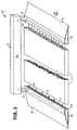
- FIG. 5 shows a variant of the object according to FIG. 3.
- a heating element 3 is arranged, which can also be replaced by one or more of the heating elements 27 to 30 according to FIG. 4 and is therefore only exemplary.
- the radiator 3 forms a structural unit with the instantaneous water heater 6, which is fixed, but detachable, placed on the radiator 3 and whose electrical connection has been omitted for the sake of simplicity.
- heating is possible using warm air or a circulating liquid. Dirt spaces that are difficult to access are avoided in this way.
- FIG. 6 shows a possibility of combining the underfloor heating 1 according to FIG. 5 with a wash basin 35, in front of which the radiator 3 is arranged as a standing surface.
- the instantaneous water heater 6 is accommodated in the wash basin 35 and connected to the heating element 3 via hidden lines 6b and 6c.
- the end pieces 33 and 34 can have aligned extensions 33a and 34a shown in dashed lines on both sides of the washstand 35 in order to avoid "dead corners" which are difficult to clean.
- the top of the instantaneous water heater can then even serve as a towel rack, so that preheated towels are always available.
- the subject of the invention also has particular advantages in apartment buildings in which the central heating is operated at night with a temperature reduction. Early risers then suffer from an unpleasant bathroom temperature, the comfort values of which are only gradually achieved even after switching up to a daytime temperature.
Landscapes
- Engineering & Computer Science (AREA)
- Physics & Mathematics (AREA)
- Thermal Sciences (AREA)
- Chemical & Material Sciences (AREA)
- Combustion & Propulsion (AREA)
- Mechanical Engineering (AREA)
- General Engineering & Computer Science (AREA)
- Central Heating Systems (AREA)
- Floor Finish (AREA)
- Steam Or Hot-Water Central Heating Systems (AREA)
Applications Claiming Priority (2)
| Application Number | Priority Date | Filing Date | Title |
|---|---|---|---|
| DE29806673U DE29806673U1 (de) | 1998-04-14 | 1998-04-14 | Fußbodenheizung |
| DE29806673U | 1998-04-14 |
Publications (2)
| Publication Number | Publication Date |
|---|---|
| EP0952405A2 true EP0952405A2 (fr) | 1999-10-27 |
| EP0952405A3 EP0952405A3 (fr) | 2001-10-24 |
Family
ID=8055671
Family Applications (1)
| Application Number | Title | Priority Date | Filing Date |
|---|---|---|---|
| EP99106731A Withdrawn EP0952405A3 (fr) | 1998-04-14 | 1999-04-03 | Chauffage par le sol |
Country Status (2)
| Country | Link |
|---|---|
| EP (1) | EP0952405A3 (fr) |
| DE (1) | DE29806673U1 (fr) |
Cited By (2)
| Publication number | Priority date | Publication date | Assignee | Title |
|---|---|---|---|---|
| EP1134504A3 (fr) * | 2000-03-16 | 2003-01-15 | C.R.M. di Giovanelli Gianfranco & C.S.n.c. | Ensemble modulaire de chauffage par le sol |
| WO2017067893A1 (fr) * | 2015-10-21 | 2017-04-27 | Asm | Lame de revetement de sol, de mur ou de plafond, chauffant ou rafraichissant |
Families Citing this family (3)
| Publication number | Priority date | Publication date | Assignee | Title |
|---|---|---|---|---|
| DE19825903A1 (de) * | 1998-06-10 | 1999-12-16 | Fuchs Fa Otto | Einrichtung zum Heizen von Bauwerken, insbesondere transportablen Bauten |
| DE10038799B4 (de) * | 2000-08-09 | 2007-07-05 | Kailan, Norbert, Dipl.-Ing. | Elektrisches Heizungssystem |
| DE102010025808B4 (de) * | 2010-07-01 | 2015-01-29 | Pedotherm Gmbh | Anordnung zur Temperierung und Lüftung von Gebäuderäumen |
Citations (3)
| Publication number | Priority date | Publication date | Assignee | Title |
|---|---|---|---|---|
| DE3100403A1 (de) | 1981-01-09 | 1982-08-12 | Hölter, Heinz, Dipl.-Ing., 4390 Gladbeck | Arbeitsplatzmatte zur humanisierung des arbeitsplatzes als waerme- oder kaeltespender |
| DE9306009U1 (de) | 1993-02-20 | 1993-08-26 | Fa. Christa Weßeling, 48599 Gronau | Wärmeboden |
| DE29703432U1 (de) | 1997-02-26 | 1997-08-21 | Heiter, Uwe, 78054 Villingen-Schwenningen | Heizmatte für Marktstände |
Family Cites Families (13)
| Publication number | Priority date | Publication date | Assignee | Title |
|---|---|---|---|---|
| CH177896A (de) | 1933-09-06 | 1935-06-30 | H Ott Gustav | Elektrische Flächenheizeinrichtung. |
| US2802088A (en) * | 1954-12-10 | 1957-08-06 | Jet Heet Inc | Heating units |
| AT322687B (de) | 1973-02-26 | 1975-06-10 | Koegler Adalbert | Vorgefertigte heizplatte, vorzugsweise fertigfussbodenelement |
| DE2351080A1 (de) | 1973-10-11 | 1975-04-24 | Werner Leschke | Auf fussboeden verlegbare, elektrisch beheizbare platte |
| DE2521374A1 (de) * | 1975-05-14 | 1976-12-02 | Rosemeier Kg | Bauelement fuer die draenage, bewaesserung, belueftung und beheizung von flaechen im erd-, grund-, wasser- und heizungsbau |
| DE2930044C2 (de) | 1979-07-24 | 1984-04-05 | Thermoval Fußbodenheizungen Entwicklungs- und Forschungsgesellschaft mbH, 1150 Wien | Flächenheizung |
| DE3020910A1 (de) | 1980-06-03 | 1981-12-10 | Lothar Pyka GmbH, 2401 Ratekau | Warmwasser-raumbeheizung |
| US5292065A (en) | 1992-06-30 | 1994-03-08 | Joachim Fiedrich | Radiant floor and wall hydronic heating systems |
| FR2698432A1 (fr) | 1992-11-24 | 1994-05-27 | Delfage Sa | Dalle chauffante d'un plancher modulaire à système de chauffage électrique par le sol, plancher modulaire et montage d'un tel plancher. |
| FR2704629B1 (fr) | 1993-04-27 | 1995-08-04 | Ho Ra | Film chauffant a structure modulaire, pour chauffage par rayonnement, et dispositif pour sa connexion. |
| DE9314110U1 (de) * | 1993-09-17 | 1994-10-27 | Sandler Energietechnik GmbH & Co. KG, 87600 Kaufbeuren | Plattenförmiger Wärmetauscher |
| US5415155A (en) * | 1993-11-08 | 1995-05-16 | Cohen; Jacques | Modular element with multiple conduits |
| DE29621729U1 (de) * | 1996-12-14 | 1997-04-10 | Geromiller, Reinhold, 88356 Ostrach | Energieübertragungssystem für Wärme oder Kälte ohne feste mechanische Verbindung mit der Wärme- bzw. Kältequelle |
-
1998
- 1998-04-14 DE DE29806673U patent/DE29806673U1/de not_active Expired - Lifetime
-
1999
- 1999-04-03 EP EP99106731A patent/EP0952405A3/fr not_active Withdrawn
Patent Citations (3)
| Publication number | Priority date | Publication date | Assignee | Title |
|---|---|---|---|---|
| DE3100403A1 (de) | 1981-01-09 | 1982-08-12 | Hölter, Heinz, Dipl.-Ing., 4390 Gladbeck | Arbeitsplatzmatte zur humanisierung des arbeitsplatzes als waerme- oder kaeltespender |
| DE9306009U1 (de) | 1993-02-20 | 1993-08-26 | Fa. Christa Weßeling, 48599 Gronau | Wärmeboden |
| DE29703432U1 (de) | 1997-02-26 | 1997-08-21 | Heiter, Uwe, 78054 Villingen-Schwenningen | Heizmatte für Marktstände |
Cited By (3)
| Publication number | Priority date | Publication date | Assignee | Title |
|---|---|---|---|---|
| EP1134504A3 (fr) * | 2000-03-16 | 2003-01-15 | C.R.M. di Giovanelli Gianfranco & C.S.n.c. | Ensemble modulaire de chauffage par le sol |
| WO2017067893A1 (fr) * | 2015-10-21 | 2017-04-27 | Asm | Lame de revetement de sol, de mur ou de plafond, chauffant ou rafraichissant |
| FR3042805A1 (fr) * | 2015-10-21 | 2017-04-28 | Asm | Lame de revetement de sol, de mur ou de plafond, chauffant ou rafraichissant |
Also Published As
| Publication number | Publication date |
|---|---|
| EP0952405A3 (fr) | 2001-10-24 |
| DE29806673U1 (de) | 1998-07-02 |
Similar Documents
| Publication | Publication Date | Title |
|---|---|---|
| DE60024789T2 (de) | Boden-, wand- und deckenheiz- oder kühlanlage | |
| DE3242942A1 (de) | Fliese | |
| DE2248228A1 (de) | Regelbare fluessigkeitsflaechenheizung mit gleichmaessiger oberflaechentemperatur | |
| DE19710072C2 (de) | Stangensystem oder Schlauchsystem für den Sanitär-oder Pflegebereich | |
| DE102008024634A1 (de) | Wohnmobil oder Wohnwagen mit Warmluft-Thermoboden | |
| EP0952405A2 (fr) | Chauffage par le sol | |
| EP0670985B1 (fr) | Element mural comportant un chauffage integre | |
| DE3226742A1 (de) | Vorgefertigte raumzelle | |
| DE4340521A1 (de) | Heizelement | |
| EP0224063A2 (fr) | Panneau de mur pour constructions de bâtiment | |
| DE1804281A1 (de) | Vorrichtung fuer Raumkonditionierung | |
| EP0743735B1 (fr) | Dispositif de regroupement de lignes d'alimentation dans un bâtiment | |
| DE2749490A1 (de) | Dach- und wandeindeckung, insbesondere fuer waermeisolierte wohnhauswaende oder -daecher | |
| DE3305040A1 (de) | Hohlboden, verfahren zu dessen herstellung und einrichtung zum beheizen oder kuehlen dieses hohlbodens | |
| AT17080U1 (de) | Raum-Modul mit Innenausbau | |
| DE3325180A1 (de) | Der modernisierung von altbauten dienender, auf eine vorhandene dielung eines raumes aufbringbarer heizkoerper fuer eine mit wasser gespeiste fussbodenheizung | |
| DE19819230C2 (de) | Heizvorrichtung für einen Raum und Verfahren zur Ausbildung einer Heizvorrichtung für einen Raum | |
| DE3420417C2 (fr) | ||
| DE594632C (fr) | ||
| DE10243263A1 (de) | Kanalsystem | |
| DE3329551C1 (de) | Fußbodenheizeinrichtung | |
| DE3238757C2 (de) | Warmluft-Heizungsanlage | |
| DE29600109U1 (de) | Naßraumboden | |
| DE10020489C2 (de) | Flächiges Heizelement | |
| DE1961882A1 (de) | Fussboden- oder Wandheizung |
Legal Events
| Date | Code | Title | Description |
|---|---|---|---|
| PUAI | Public reference made under article 153(3) epc to a published international application that has entered the european phase |
Free format text: ORIGINAL CODE: 0009012 |
|
| AK | Designated contracting states |
Kind code of ref document: A2 Designated state(s): AT BE CH CY DE DK ES FI FR GB GR IE IT LI LU MC NL PT SE |
|
| AX | Request for extension of the european patent |
Free format text: AL;LT;LV;MK;RO;SI |
|
| PUAL | Search report despatched |
Free format text: ORIGINAL CODE: 0009013 |
|
| AK | Designated contracting states |
Kind code of ref document: A3 Designated state(s): AT BE CH CY DE DK ES FI FR GB GR IE IT LI LU MC NL PT SE |
|
| AX | Request for extension of the european patent |
Free format text: AL;LT;LV;MK;RO;SI |
|
| AKX | Designation fees paid | ||
| REG | Reference to a national code |
Ref country code: DE Ref legal event code: 8566 |
|
| STAA | Information on the status of an ep patent application or granted ep patent |
Free format text: STATUS: THE APPLICATION IS DEEMED TO BE WITHDRAWN |
|
| 18D | Application deemed to be withdrawn |
Effective date: 20020425 |