EP0952426A1 - Uhrwerk mit einem induktiven oder kapazitiven Sensor zur Detektion von mindestens einem Drehwinkel eines Zahnrades innerhalb des Uhrwerkes - Google Patents
Uhrwerk mit einem induktiven oder kapazitiven Sensor zur Detektion von mindestens einem Drehwinkel eines Zahnrades innerhalb des Uhrwerkes Download PDFInfo
- Publication number
- EP0952426A1 EP0952426A1 EP98110729A EP98110729A EP0952426A1 EP 0952426 A1 EP0952426 A1 EP 0952426A1 EP 98110729 A EP98110729 A EP 98110729A EP 98110729 A EP98110729 A EP 98110729A EP 0952426 A1 EP0952426 A1 EP 0952426A1
- Authority
- EP
- European Patent Office
- Prior art keywords
- wheel
- plate
- axis
- sensor
- opening
- Prior art date
- Legal status (The legal status is an assumption and is not a legal conclusion. Google has not performed a legal analysis and makes no representation as to the accuracy of the status listed.)
- Granted
Links
Images



Classifications
-
- G—PHYSICS
- G01—MEASURING; TESTING
- G01D—MEASURING NOT SPECIALLY ADAPTED FOR A SPECIFIC VARIABLE; ARRANGEMENTS FOR MEASURING TWO OR MORE VARIABLES NOT COVERED IN A SINGLE OTHER SUBCLASS; TARIFF METERING APPARATUS; MEASURING OR TESTING NOT OTHERWISE PROVIDED FOR
- G01D5/00—Mechanical means for transferring the output of a sensing member; Means for converting the output of a sensing member to another variable where the form or nature of the sensing member does not constrain the means for converting; Transducers not specially adapted for a specific variable
- G01D5/12—Mechanical means for transferring the output of a sensing member; Means for converting the output of a sensing member to another variable where the form or nature of the sensing member does not constrain the means for converting; Transducers not specially adapted for a specific variable using electric or magnetic means
- G01D5/14—Mechanical means for transferring the output of a sensing member; Means for converting the output of a sensing member to another variable where the form or nature of the sensing member does not constrain the means for converting; Transducers not specially adapted for a specific variable using electric or magnetic means influencing the magnitude of a current or voltage
- G01D5/20—Mechanical means for transferring the output of a sensing member; Means for converting the output of a sensing member to another variable where the form or nature of the sensing member does not constrain the means for converting; Transducers not specially adapted for a specific variable using electric or magnetic means influencing the magnitude of a current or voltage by varying inductance, e.g. by a movable armature
- G01D5/2006—Mechanical means for transferring the output of a sensing member; Means for converting the output of a sensing member to another variable where the form or nature of the sensing member does not constrain the means for converting; Transducers not specially adapted for a specific variable using electric or magnetic means influencing the magnitude of a current or voltage by varying inductance, e.g. by a movable armature by influencing the self-induction of one or more coils
- G01D5/202—Mechanical means for transferring the output of a sensing member; Means for converting the output of a sensing member to another variable where the form or nature of the sensing member does not constrain the means for converting; Transducers not specially adapted for a specific variable using electric or magnetic means influencing the magnitude of a current or voltage by varying inductance, e.g. by a movable armature by influencing the self-induction of one or more coils by movable a non-ferromagnetic conductive element
-
- G—PHYSICS
- G01—MEASURING; TESTING
- G01B—MEASURING LENGTH, THICKNESS OR SIMILAR LINEAR DIMENSIONS; MEASURING ANGLES; MEASURING AREAS; MEASURING IRREGULARITIES OF SURFACES OR CONTOURS
- G01B7/00—Measuring arrangements characterised by the use of electric or magnetic techniques
- G01B7/30—Measuring arrangements characterised by the use of electric or magnetic techniques for measuring angles or tapers; for testing the alignment of axes
-
- G—PHYSICS
- G04—HOROLOGY
- G04C—ELECTROMECHANICAL CLOCKS OR WATCHES
- G04C3/00—Electromechanical clocks or watches independent of other time-pieces and in which the movement is maintained by electric means
- G04C3/14—Electromechanical clocks or watches independent of other time-pieces and in which the movement is maintained by electric means incorporating a stepping motor
-
- G—PHYSICS
- G04—HOROLOGY
- G04D—APPARATUS OR TOOLS SPECIALLY DESIGNED FOR MAKING OR MAINTAINING CLOCKS OR WATCHES
- G04D7/00—Measuring, counting, calibrating, testing or regulating apparatus
- G04D7/12—Timing devices for clocks or watches for comparing the rate of the oscillating member with a standard
- G04D7/1207—Timing devices for clocks or watches for comparing the rate of the oscillating member with a standard only for measuring
-
- H—ELECTRICITY
- H03—ELECTRONIC CIRCUITRY
- H03K—PULSE TECHNIQUE
- H03K17/00—Electronic switching or gating, i.e. not by contact-making and –breaking
- H03K17/94—Electronic switching or gating, i.e. not by contact-making and –breaking characterised by the way in which the control signals are generated
- H03K17/965—Switches controlled by moving an element forming part of the switch
- H03K17/97—Switches controlled by moving an element forming part of the switch using a magnetic movable element
-
- H—ELECTRICITY
- H03—ELECTRONIC CIRCUITRY
- H03K—PULSE TECHNIQUE
- H03K17/00—Electronic switching or gating, i.e. not by contact-making and –breaking
- H03K17/94—Electronic switching or gating, i.e. not by contact-making and –breaking characterised by the way in which the control signals are generated
- H03K17/965—Switches controlled by moving an element forming part of the switch
- H03K17/975—Switches controlled by moving an element forming part of the switch using a capacitive movable element
-
- H—ELECTRICITY
- H03—ELECTRONIC CIRCUITRY
- H03K—PULSE TECHNIQUE
- H03K17/00—Electronic switching or gating, i.e. not by contact-making and –breaking
- H03K17/94—Electronic switching or gating, i.e. not by contact-making and –breaking characterised by the way in which the control signals are generated
- H03K17/965—Switches controlled by moving an element forming part of the switch
- H03K17/97—Switches controlled by moving an element forming part of the switch using a magnetic movable element
- H03K2017/9706—Inductive element
-
- H—ELECTRICITY
- H03—ELECTRONIC CIRCUITRY
- H03K—PULSE TECHNIQUE
- H03K2217/00—Indexing scheme related to electronic switching or gating, i.e. not by contact-making or -breaking covered by H03K17/00
- H03K2217/94—Indexing scheme related to electronic switching or gating, i.e. not by contact-making or -breaking covered by H03K17/00 characterised by the way in which the control signal is generated
- H03K2217/94057—Rotary switches
- H03K2217/94068—Rotary switches with magnetic detection
Definitions
- the present invention relates to a timepiece comprising a timepiece movement, provided with an analog display and at least one mobile integral in rotation with an indicator or rotary display means of this analog display, and a detection device. at least one angular reference position of said mobile, this detection device comprising a magnetic or capacitive sensor.
- the invention relates to a device for detecting at least one angular reference position of a toothed wheel of the train of a watch movement.
- optical devices for detecting at least one angular position of the wheel reference belonging to the train of a watch movement All of these optical detection devices are relatively complex. They require a light source and a light receiver remote from this source. The mounting of an optical detection device is often delicate given the precise adjustment necessary between the light source, the receiver and the wheel or wheels associated with this device. In the context of the present invention, it is therefore planned to dispense with any optical system for detecting the position of a wheel in a watch movement.
- a system for detecting the position of coaxial wheels respectively associated with coaxial hands of a watch movement is known from the English abstract of international application WO 97/45705.
- On each solid toothed wheel are arranged several discrete parts of a magnetic hard film which define an identification pattern for a magnetic sensor without contact.
- Each of the wheels for which it is intended to be able to detect the angular position is associated with its own magnetic sensor.
- the amplitude of the signal detected by these magnetic sensors varies depending on whether they are located in front of a segment of magnetic material or not, as shown in Figures 3 and 4 of this international patent application.
- each wheel associated with a magnetic sensor must be provided with separate segments or parts of a solid film of magnetic material arranged on one face of the toothed wheel.
- the manufacturing cost of the wheels is therefore increased and the arrangement of the identification pattern is provided on a plate full of the toothed wheel, which can be a drawback for the running of the watch movement.
- the wheel plates are therefore formed from at least two different materials, namely the material forming the base of the wheel plate and the magnetic material arranged on the surface of this base.
- An object of the present invention is to overcome the aforementioned drawbacks by providing a timepiece comprising a device for non-contact detection of the angular position of at least one reference half-axis of a wheel which is of simple construction and which generates a less complicated watch movement.
- the wheel associated with the contactless sensor can have a plate made of a single conventional material for the wheels of a watch movement, in particular an electrically conductive metal such as brass.
- the plate of the wheel associated with the detection device does not have to be made of a permanently magnetized material, nor to support magnetized elements with the type of contactless sensor selected.
- the invention makes it possible to detect at least one geometric reference half-axis of a wheel formed in a conventional manner with appropriate machining of the plate of this wheel, in particular of said at least one opening.
- the geometric reference half-axis of the wheel starts perpendicularly from the geometric axis of rotation of this wheel and passes through the geometric center of said opening.
- a single opening provided in the wheel plate allows the detection device according to the invention to determine the angular position of the wheel.
- the machining of an opening in a wheel plate is a very inexpensive operation, which is also already provided in certain types of wheels to limit the weight of the wheel and also the cost of material.
- the present invention does not generate any complication of the conventional watch movement to allow the detection of the angular position of a wheel.
- the plate of said wheel associated with the detection device has in its intermediate region at least one opening and a radial arm, the central direction of this arm defining a geometric reference half-axis of this wheel, the angular position can be detected by the detection device according to the invention.
- the angular position of a wheel can be determined by a radial and median direction of an opening or of an arm, in particular in the form of an annular sector.
- an inductive sensor since the developments and prototypes made in the context of the present invention were carried out with a newly developed integrated inductive sensor.
- the results obtained with this integrated inductive sensor comprising a single plane coil in small spiral give very good results.
- an integrated capacitive type sensor can also be provided in place of an inductive sensor. Note however that the inductive sensor is less sensitive to the environment and to disturbances caused by manufacturing and mounting tolerances than a capacitive sensor.
- the watch movement 2 comprises a toothed wheel 4 with a toothing 6 defined by the outer edge of the plate 8.
- the wheel 4 further comprises a shaft 10 defining a geometric axis of rotation 12.
- the watch movement 2 is associated with an analog display comprising a rotary indicator 14 fixedly mounted on the shaft 10.
- the indicator 14 can be used to indicate the hour, minute, second or any other useful information provided for an analog display.
- the plate 8 is fixedly mounted on the shaft 10 so that the indicator 14 is integral with this plate 8.
- the plate 8 has a circular opening 16 in its intermediate region, that is to say between the central hole 18 provided for the passage of the shaft 10 and the toothing 6.
- the sensor 20 can, in an equivalent manner, be arranged above the plate 8 so that the planar coil 24 is at least partially located opposite the opening 16 in at least one given angular position of the wheel 4
- the central magnetic axis 26 of the spiral forming the planar coil 24 Preferably, provision is made for the central magnetic axis 26 of the spiral forming the planar coil 24 to pass substantially through the center 28 of the opening 16 in a given angular position taken by the wheel 4, as shown in FIG. 1
- the angle of reference ⁇ ref is defined between a reference direction RM of the watch movement and the geometric reference half-axis RD of the sensor 20, parallel to the plate 8, which starts from the geometric axis 12 and crosses the central magnetic axis 26 of the reel 24.
- the reference geometric half-axis R1 of the wheel 4 starts from the geometric axis 12 and passes through the center 28 of the circular opening 16. In FIG. 1, the half-axes R1 and RD are combined.
- the indicator 14 may have any angular offset relative to the direction of the semi-axis R1.
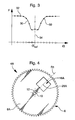
- FIG. 3 schematically shows a graph 30 defined by measurement points 32 obtained by the sensor 20.
- the plate 8 is made of a non-magnetized material, that is to say is not made of a permanent magnet, but by a material of which a proximity variation relative to the planar coil 24 generates a variation of at least one parameter or variable of the sensor 20 on which a measurement signal supplied by this sensor depends.
- the inductive sensor provided in this embodiment includes an electronic circuit similar to that described in document EP 0746100, this sensor defining a differential relaxation oscillator.
- This measurement signal supplied by the sensor 20 is representative of a frequency determined by the electronic circuit of this sensor, this frequency varying as a function of the variation in the presence of the material constituting the plate 8 above or below the detection member defined by the coil 24.
- the variation of said frequency results from the variation of the value of the inductance of the coil 24 within the electronic circuit of the sensor 20.
- the frequency has a high value.
- Curve 30 schematically defines the evolution of the value of the frequency generated by the sensor as a function of the angular position of the reference half-axis R1 of the wheel 4 which, as said previously, starts from the geometric axis 12 and passes through the center 28 of the circular opening 16.
- the graph 30 may have a peak instead of a dip depending on the construction of the electronic circuit provided or of the material constituting the plate 8.
- the material of the plate 8 is either an electrically conductive metal or a material of high magnetic permeability.
- the selected material is a conductive metal having a magnetic permeability equal to 1 or close to 1, that is to say a non-ferromagnetic metal such as aluminum or brass widely used for the manufacture of wheels and the like. parts of watch movements.
- the width of the peak or the trough in the graph 30 is a function of the angular dimension of the reference opening or, as will be described below, of the reference radial arm. It is possible to provide a small angular dimension of this opening (a slit) or of this radial arm and / or a low measurement frequency and / or a step-by-step drive defining angular jumps sufficiently large for a single point of measurement essentially defines the peak or trough. In such a case, it suffices to detect when a measurement gives a frequency value lower, respectively higher than a threshold value for detecting the passage of the slit, respectively of the peak (or vice versa depending on the sensor 20 provided).
- Such a measurement thus corresponds to an angular position ⁇ of the semi-axis R1 equal to ⁇ ref . Consequently, the angular position of the wheel is determined directly when the reference half-axes RD and R1 are merged without requiring a subsequent determination of the measurement of the sensor which corresponds to this situation. It will be noted that such a particular case simplifies the processing of the measurement results, but generally reduces the sensitivity of the detection device according to the invention.
- equivalent analyzes are also applicable.
- the detection device is arranged to allow several successive measurements to be made, in particular at a given set frequency. Then, it includes a memory for recording one or more succession (s) of measurement results in an embodiment where the measurement curve for the detection of the half-axis R1 is similar to the curve 30.
- the temporal evolution of the rotation resulting from the control of the drive means of the wheel 4 must be stored in an appropriate form to allow the instantaneous angular offset of the semi-axis R1 to be determined relative to ⁇ ref once the result measurement corresponding to the angular position ⁇ of the semi-axis R1 equal to ⁇ ref has been identified.
- an initialization command is provided where the motor driving this wheel 4 is controlled in a rapid mode and the detection device is activated so as to determine the angular position of the half-axis R1 during its passage above or below the coil 24 of the sensor 20.
- FIG. 4 In Figure 4 is shown a wheel 4A having a plate 8A which has a square opening 16A.
- the reference half-axis R1 passes through the geometric center 28A of the opening 16A.
- This wheel 4A forms an alternative embodiment of the wheel 4 of FIG. 1.
- FIG. 5 schematically represents a second embodiment of a timepiece according to the invention in which the sensor 20 is identical to that described in FIGS. 1 and 2.
- the wheel 4B associated with the sensor 20 has two openings 40 and 42 in the form of an annular sector.
- the opening 40 defines an angle at the center of 60 ° while the opening 42 defines an angle at the center of 120 °.
- These two openings are located in the intermediate region of the plate 8B located between the central hole provided for the passage of the shaft 10 and the toothing 6.
- the two openings 40 and 42 are separated from each other by two material parts 44 and 46 respectively defining angles at the center of 60 ° and 120 °.
- the measurements carried out repeatedly during the rotation of the wheel 4B by the sensor 20 makes it possible to determine the angular positions of the reference half-axes R2 and R6 of this wheel.
- the detection by the sensor 20 of the angular positions of the reference half-axes R4 and R8, respectively combined with the median directions of the annular parts 46 and 44, is carried out in an equivalent manner to the detection of the angular positions of the half-axes R2 and R6 .
- the passage over the coil 24 of the annular section 44 or 46 generates an increase in the frequency measured by the sensor, as shown in FIG. 6.
- the frequency measured by the sensor corresponds substantially to F min , while the measured frequency has substantially the value F max when the coil 24 is entirely covered by one of the annular sections 44 or 46. Since the curve resulting from the measurements made by the sensor 20 during the passage of a full annular section defines a curve 48 substantially symmetrical, the electronic means associated with the sensor make it possible to determine the middle position given by the vertical straight line 50, corresponding to the angular position ⁇ ref , in the manner described above with reference to FIGS. 1 to 3.
- the configuration of the plate 8B of the wheel 4B shown in FIG. 5 makes it possible to define four other reference half-axes R1, R3, R5 and R7 of the wheel 4B.
- the sensor 20 is sensitive to a variation in the presence of the material forming the plate 8B above or below the coil 24.
- the frequency of the measurement signal from the sensor 20 goes from a value F max to a value F min .
- FIG. 7 is shown the curve defined by the various measurement points obtained during a transition from an opening 40 or 42 to an arm or annular part 44 or 46.
- the detection device provided in the present embodiment, it is possible to detect the edge of an opening when this edge defines a radial direction of the plate, as is the case in FIG. 5.
- An annular sector defined by an opening or by a material part in the intermediate region of the plate makes it possible to define three half-axes of references of the wheel comprising this plate.
- This is apparent in particular from the graph 48 shown in FIG. 6 which corresponds substantially to the passage of the annular sector 44 above the coil 24 of the sensor 20.
- the analysis of the graph 48 makes it possible to determine which measurement point corresponds to the alignment of the half-axis R8 on the reference half-axis RD of the sensor and the measurement points corresponding to the alignment of the half-axis R7, respectively R1 on the half-axis RD. These latter measurement points correspond respectively to the angles ⁇ 1 and ⁇ 2 of FIG. 6 when the wheel 4B rotates clockwise.
- a measurement of ⁇ makes it possible to determine whether it is the annular part 44 or 46 which has passed over the coil 24.
- ⁇ the width at mid-height of a hollow in an equivalent graph for the measurement points resulting from the passage of an opening 40 or 42 facing the coil 24, it is possible to determine which of these openings has passed over the coil 24. It follows from these considerations that the analysis of the successive measurements by the sensor 20 during the rotation of the wheel 4B makes it possible to unequivocally determine the angular positions of each of the reference half-axes R1 to R8.
- the plate 8B thus defines six reference half-axes detectable by the sensor 20 which are offset relative to each other by an angle of 60 °.
- two reference half-axes R6 and R8 are also detectable. Once the angular position of a half-axis has been determined, the angular positions of the other half-axes are also determined. In general, a single reference half-axis is sufficient to determine the angular position of a wheel in an initialization mode and to check over time a correct advance of the wheel relative to a reference advance determined by reference means.
- FIG. 8 shows another embodiment of a wheel 4C associated with a detection device according to the invention.
- This detection device again comprises a sensor 20 provided with a flat spiral coil 24.
- the plate 8C has four openings 60 to 63 defining four radial arms 64 to 67 connecting the hub 68 to the rim 69 of the wheel 4C.
- the radial arm 64 has an angular dimension greater than the other three arms.
- the center line of this arm 64 defines the geometric reference half-axis R1 of the wheel 4C which coincides with this center line.
- This embodiment is advantageous in that the plate 8C has openings distributed substantially uniformly so that this plate is substantially balanced.
- Figures 9 and 10 show two variants of another embodiment.
- the plate 8D of the wheel 4D shown in FIG. 9 defines in particular three reference half-axes R1, R2 and R3 which are angularly offset by 120 ° and are defined respectively by the median lines of the openings 70, 71 and 72.
- the angular dimension of the opening 70 is greater than the angular dimensions respective openings 71 and 72 which are identical.
- the openings 71 and 72 are identical, they nevertheless define the reference half-axes R2 and R3 unequivocally since the wheel 4D rotates in a determined direction, for example clockwise.
- FIG. 10 represents a wheel 4E, the plate 8E of which also has three annular parts separated by three openings 74, 75 and 76.
- the three annular parts or radial arms 77, 78 and 79 each have a different specific radial dimension, namely 80 °, 60 ° and 40 °.
- the half-axes R1, R2 and R3 are detected unequivocally whatever the direction of rotation of the wheel.
Landscapes
- Physics & Mathematics (AREA)
- General Physics & Mathematics (AREA)
- Measurement Of Length, Angles, Or The Like Using Electric Or Magnetic Means (AREA)
- Transmission And Conversion Of Sensor Element Output (AREA)
- Electromechanical Clocks (AREA)
Applications Claiming Priority (2)
| Application Number | Priority Date | Filing Date | Title |
|---|---|---|---|
| CH93798 | 1998-04-24 | ||
| CH93798 | 1998-04-24 |
Publications (2)
| Publication Number | Publication Date |
|---|---|
| EP0952426A1 true EP0952426A1 (de) | 1999-10-27 |
| EP0952426B1 EP0952426B1 (de) | 2003-09-03 |
Family
ID=4198653
Family Applications (1)
| Application Number | Title | Priority Date | Filing Date |
|---|---|---|---|
| EP98110729A Expired - Lifetime EP0952426B1 (de) | 1998-04-24 | 1998-06-11 | Uhrwerk mit einem induktiven oder kapazitiven Sensor zur Detektion von mindestens einem Drehwinkel eines Zahnrades innerhalb des Uhrwerkes |
Country Status (5)
| Country | Link |
|---|---|
| US (1) | US6330207B1 (de) |
| EP (1) | EP0952426B1 (de) |
| JP (1) | JPH11326555A (de) |
| CN (1) | CN1191455C (de) |
| DE (1) | DE69817764T2 (de) |
Cited By (6)
| Publication number | Priority date | Publication date | Assignee | Title |
|---|---|---|---|---|
| EP1607808A1 (de) * | 2004-06-15 | 2005-12-21 | Asulab S.A. | Verfahren zur Synchronisierung der analogen Anzeige einer Uhr mit einem elektronischen Taktgeber |
| US7154815B2 (en) | 2003-07-14 | 2006-12-26 | Asulab S.A. | Astronomical timepiece |
| US7440359B2 (en) | 2006-10-03 | 2008-10-21 | The Swatch Group Research And Development Ltd | Timepiece including means for determining the angular position of an analogue indicator of the timepiece |
| EP3037898A1 (de) | 2014-12-23 | 2016-06-29 | ETA SA Manufacture Horlogère Suisse | Elektromechanisches gerät, das einen kapazitiven detektor der winkelposition eines mobilen elementes umfasst, und verfahren zur detektion der winkelposition eines mobilen elementes |
| CN106289028A (zh) * | 2015-06-04 | 2017-01-04 | 亿科钟表科技(深圳)有限公司 | 表壳分度检测装置 |
| EP3242168A1 (de) * | 2016-05-04 | 2017-11-08 | ETA SA Manufacture Horlogère Suisse | Elektromechanisches uhrwerk, das eine vorrichtung zur erfassung der winkelposition eines rads umfasst |
Families Citing this family (12)
| Publication number | Priority date | Publication date | Assignee | Title |
|---|---|---|---|---|
| CN1132077C (zh) * | 1999-05-06 | 2003-12-24 | 阿苏拉布股份有限公司 | 包括用于指示同轴模拟显示指针之角度位置的装置的钟表 |
| JP2002340506A (ja) * | 2001-05-11 | 2002-11-27 | Seiko Instruments Inc | 位置検出装置及びこれを用いた時計針位置検出装置 |
| JP4206713B2 (ja) * | 2002-09-05 | 2009-01-14 | 株式会社デンソー | 指示計器 |
| DE102004002825A1 (de) * | 2004-01-12 | 2005-08-04 | E.G.O. Elektro-Gerätebau GmbH | Bedieneinrichtung mit einem kapazitiven Sensorelement und Elektrogerät mit einer solchen Bedieneinrichtung |
| CN102486388B (zh) * | 2010-12-02 | 2014-05-14 | 联合汽车电子有限公司 | 编码器计数系统正确性测试方法 |
| JP5618885B2 (ja) * | 2011-03-28 | 2014-11-05 | 株式会社ケーヒン | 車両のアクセル開度検出装置 |
| EP3147726A1 (de) * | 2015-09-24 | 2017-03-29 | ETA SA Manufacture Horlogère Suisse | Anzeigevorrichtung für uhr, die einen anzeiger mit starker umwucht umfasst |
| CN106057646B (zh) * | 2016-07-06 | 2019-06-25 | 广东先导先进材料股份有限公司 | 一种半导体晶片磨边工艺 |
| EP3333646A1 (de) * | 2016-12-06 | 2018-06-13 | ETA SA Manufacture Horlogère Suisse | Tragbarer gegenstand, der einen drehbaren steuerstab umfasst, dessen betätigung durch zwei induktionssensoren erkannt wird |
| US10527460B2 (en) * | 2017-11-07 | 2020-01-07 | Pixart Imaging Inc. | Gear position detection device, wrist watch and operating method thereof |
| DE102018107416A1 (de) * | 2018-03-28 | 2019-10-02 | HELLA GmbH & Co. KGaA | Vorrichtung zur Bestimmung eines Drehwinkels und/oder eines Drehmoments |
| FI130151B (fi) * | 2021-06-04 | 2023-03-15 | Navigil Ltd | Analoginen älykello |
Citations (4)
| Publication number | Priority date | Publication date | Assignee | Title |
|---|---|---|---|---|
| FR1512207A (fr) * | 1966-02-23 | 1968-02-02 | Montan Forschung Dr Hans Zille | Dispositif de mesure électrique de grandeurs mécaniques |
| DE3828810A1 (de) * | 1988-08-25 | 1990-03-01 | Kienzle Uhrenfabriken Gmbh | Vorrichtung zur anzeigestellungsdetektion fuer eine analoge elektronische uhr, insbesondere eine funkgesteuerte uhr |
| EP0746100A1 (de) | 1995-06-01 | 1996-12-04 | Sentron Ag | Schaltungsanordnung zum Betrieb eines resistiven, kapazitiven oder induktiven Sensors |
| WO1997045705A1 (fr) | 1996-05-24 | 1997-12-04 | Seiko Epson Corporation | Detecteur de position, carte codeur, procede de detection de position, horloge et dispositif electronique |
Family Cites Families (10)
| Publication number | Priority date | Publication date | Assignee | Title |
|---|---|---|---|---|
| FR2170989B1 (de) * | 1972-02-10 | 1976-07-23 | Thomson Csf | |
| JPS5762031B2 (de) * | 1975-02-07 | 1982-12-27 | Seiko Koki Kk | |
| DE2749006C3 (de) * | 1977-11-02 | 1981-12-17 | Urgos Uhrenfabrik Schwenningen Haller, Jauch und Pabst GmbH& Co, 7220 Schwenningen | Elektronische Korrektureinrichtung für eine Pendeluhr |
| DE3510861C2 (de) * | 1984-11-09 | 1986-09-25 | Gebrüder Junghans GmbH, 7230 Schramberg | Anzeigestellungs-Detektionseinrichtung für eine Uhr, insbesondere eine Funkuhr |
| CH680696B5 (de) * | 1989-11-03 | 1993-04-30 | Rolex Montres | |
| JP3064396B2 (ja) * | 1990-11-08 | 2000-07-12 | カシオ計算機株式会社 | 電子時計 |
| US5202858A (en) * | 1990-11-28 | 1993-04-13 | Casio Computer Co., Ltd. | Analog electronic timepiece having an electric-optical display device |
| JP2577839B2 (ja) * | 1991-10-02 | 1997-02-05 | リズム時計工業株式会社 | アナログ時計装置 |
| CH685588B5 (fr) * | 1993-09-16 | 1996-02-29 | Ebauchesfabrik Eta Ag | Piece d'horlogerie a affichage analogique pouvant fournir une ou plusieurs informations alphanumeriques sur l'etat d'un mode de fonctionnement ou d'un evenement programme. |
| DE29714186U1 (de) * | 1997-08-08 | 1998-12-10 | Gebrüder Junghans GmbH, 78713 Schramberg | Funkuhrwerk |
-
1998
- 1998-06-11 DE DE69817764T patent/DE69817764T2/de not_active Expired - Lifetime
- 1998-06-11 EP EP98110729A patent/EP0952426B1/de not_active Expired - Lifetime
-
1999
- 1999-04-22 US US09/296,130 patent/US6330207B1/en not_active Expired - Lifetime
- 1999-04-23 JP JP11116078A patent/JPH11326555A/ja active Pending
- 1999-04-26 CN CNB991051920A patent/CN1191455C/zh not_active Expired - Lifetime
Patent Citations (4)
| Publication number | Priority date | Publication date | Assignee | Title |
|---|---|---|---|---|
| FR1512207A (fr) * | 1966-02-23 | 1968-02-02 | Montan Forschung Dr Hans Zille | Dispositif de mesure électrique de grandeurs mécaniques |
| DE3828810A1 (de) * | 1988-08-25 | 1990-03-01 | Kienzle Uhrenfabriken Gmbh | Vorrichtung zur anzeigestellungsdetektion fuer eine analoge elektronische uhr, insbesondere eine funkgesteuerte uhr |
| EP0746100A1 (de) | 1995-06-01 | 1996-12-04 | Sentron Ag | Schaltungsanordnung zum Betrieb eines resistiven, kapazitiven oder induktiven Sensors |
| WO1997045705A1 (fr) | 1996-05-24 | 1997-12-04 | Seiko Epson Corporation | Detecteur de position, carte codeur, procede de detection de position, horloge et dispositif electronique |
Cited By (9)
| Publication number | Priority date | Publication date | Assignee | Title |
|---|---|---|---|---|
| US7154815B2 (en) | 2003-07-14 | 2006-12-26 | Asulab S.A. | Astronomical timepiece |
| EP1607808A1 (de) * | 2004-06-15 | 2005-12-21 | Asulab S.A. | Verfahren zur Synchronisierung der analogen Anzeige einer Uhr mit einem elektronischen Taktgeber |
| US7218577B2 (en) | 2004-06-15 | 2007-05-15 | Asulab, S.A. | Method for synchronising an analog display of a timepiece with its electronic time base |
| US7440359B2 (en) | 2006-10-03 | 2008-10-21 | The Swatch Group Research And Development Ltd | Timepiece including means for determining the angular position of an analogue indicator of the timepiece |
| EP3037898A1 (de) | 2014-12-23 | 2016-06-29 | ETA SA Manufacture Horlogère Suisse | Elektromechanisches gerät, das einen kapazitiven detektor der winkelposition eines mobilen elementes umfasst, und verfahren zur detektion der winkelposition eines mobilen elementes |
| EP3037899A1 (de) | 2014-12-23 | 2016-06-29 | ETA SA Manufacture Horlogère Suisse | Uhr, die eine triebfeder mit einstellbarer winkelposition umfasst |
| CN106289028A (zh) * | 2015-06-04 | 2017-01-04 | 亿科钟表科技(深圳)有限公司 | 表壳分度检测装置 |
| EP3242168A1 (de) * | 2016-05-04 | 2017-11-08 | ETA SA Manufacture Horlogère Suisse | Elektromechanisches uhrwerk, das eine vorrichtung zur erfassung der winkelposition eines rads umfasst |
| US10061271B2 (en) | 2016-05-04 | 2018-08-28 | Eta Sa Manufacture Horlogère Suisse | Electromechanical timepiece movement comprising a device for detection of the angular position of a wheel |
Also Published As
| Publication number | Publication date |
|---|---|
| DE69817764D1 (de) | 2003-10-09 |
| CN1234538A (zh) | 1999-11-10 |
| JPH11326555A (ja) | 1999-11-26 |
| US6330207B1 (en) | 2001-12-11 |
| CN1191455C (zh) | 2005-03-02 |
| EP0952426B1 (de) | 2003-09-03 |
| HK1023627A1 (en) | 2000-09-15 |
| DE69817764T2 (de) | 2004-07-15 |
Similar Documents
| Publication | Publication Date | Title |
|---|---|---|
| EP0952426B1 (de) | Uhrwerk mit einem induktiven oder kapazitiven Sensor zur Detektion von mindestens einem Drehwinkel eines Zahnrades innerhalb des Uhrwerkes | |
| EP2452160B1 (de) | Multiperiodischer absoluter positionssensor | |
| EP2338030B2 (de) | Magnetpositionssensor mit feldrichtungsmessung und flusskollektor | |
| EP1949036B1 (de) | Magnetischer winkelpositionssensor für eine umdrehung bis 360° | |
| EP0960361B1 (de) | Uhrwerk mit kapazitiver detektionsvorrichtung | |
| EP1017967B1 (de) | Digitaler geber zur messung einer relativen position | |
| EP3037898B1 (de) | Elektromechanisches gerät, das einen kapazitiven detektor der winkelposition eines mobilen elementes umfasst, und verfahren zur detektion der winkelposition eines mobilen elementes | |
| FR2872896A1 (fr) | Capteur de position, notamment destine a la mesure de la torsion d'une colonne de direction | |
| WO1996008727A1 (fr) | Capteur incremental de vitesse et/ou de position | |
| FR2635873A1 (fr) | Procede et appareil de mesure de la rotation d'un corps | |
| FR2845469A1 (fr) | Capteur de position analogique a reluctance variable | |
| FR2859276A1 (fr) | Dispositif de determination de position angulaire a detecteur d'anomalie de fonctionnement | |
| EP0800055B1 (de) | Linear- und Winkelpositionssensor | |
| EP0969266B1 (de) | Vorrichtung und Verfahren zur Bestimmung der Winkellage von mindestens zwei koaxialen Rädern mit einem einzigen Sensor | |
| EP1550844B1 (de) | Einrichtung zur Detektion des Drehens eines rotierenden Elements, wie einer Wasserzählerturbine | |
| EP3671135B1 (de) | System und verfahren zur bestimmung mindestens eines parameters der winkelbewegung einer achse | |
| EP3751291A1 (de) | Anordnung aus rad und bremse eines luftfahrzeugs | |
| CH679086A5 (de) | ||
| EP0158557B1 (de) | Vorrichtung zur Unterdrückung von Vibrationsgeräuschen in einem Laserkreisel und Anwendung dieser Vorrichtung | |
| CH710522A2 (fr) | Appareil électromécanique comportant un dispositif de détection capacitif de la position angulaire d'un mobile, et procédé de détection de la position angulaire d'un mobile. | |
| EP2313746A2 (de) | Mehrpolcodierer für einen positionssensor und detektionsanordnung mit einem solchen codierer mit mindestens einem positionssensor | |
| FR2743882A1 (fr) | Dispositif et procede de reperage de position d'un element mobile, en particulier pour un instrument de mesure | |
| FR2677757A1 (fr) | Capteur de position angulaire absolue a reluctance variable. | |
| FR3080679A1 (fr) | Dispositif de detection de la position angulaire d'un rotor d'une machine electrique tournante | |
| CH721554A2 (fr) | Procédé de détermination du déplacement axial ou de la position axiale d'un arbre d'un dispositif de commande électronique |
Legal Events
| Date | Code | Title | Description |
|---|---|---|---|
| PUAI | Public reference made under article 153(3) epc to a published international application that has entered the european phase |
Free format text: ORIGINAL CODE: 0009012 |
|
| AK | Designated contracting states |
Kind code of ref document: A1 Designated state(s): CH DE FR GB IT LI |
|
| AX | Request for extension of the european patent |
Free format text: AL;LT;LV;MK;RO;SI |
|
| 17P | Request for examination filed |
Effective date: 20000427 |
|
| AKX | Designation fees paid |
Free format text: CH DE FR GB IT LI |
|
| GRAH | Despatch of communication of intention to grant a patent |
Free format text: ORIGINAL CODE: EPIDOS IGRA |
|
| GRAS | Grant fee paid |
Free format text: ORIGINAL CODE: EPIDOSNIGR3 |
|
| GRAA | (expected) grant |
Free format text: ORIGINAL CODE: 0009210 |
|
| AK | Designated contracting states |
Kind code of ref document: B1 Designated state(s): CH DE FR GB IT LI |
|
| PG25 | Lapsed in a contracting state [announced via postgrant information from national office to epo] |
Ref country code: IT Free format text: LAPSE BECAUSE OF FAILURE TO SUBMIT A TRANSLATION OF THE DESCRIPTION OR TO PAY THE FEE WITHIN THE PRE;WARNING: LAPSES OF ITALIAN PATENTS WITH EFFECTIVE DATE BEFORE 2007 MAY HAVE OCCURRED AT ANY TIME BEFORE 2007. THE CORRECT EFFECTIVE DATE MAY BE DIFFERENT FROM THE ONE RECORDED.SCRIBED TIME-LIMIT Effective date: 20030903 |
|
| REG | Reference to a national code |
Ref country code: GB Ref legal event code: FG4D Free format text: NOT ENGLISH |
|
| REG | Reference to a national code |
Ref country code: CH Ref legal event code: EP |
|
| REF | Corresponds to: |
Ref document number: 69817764 Country of ref document: DE Date of ref document: 20031009 Kind code of ref document: P |
|
| REG | Reference to a national code |
Ref country code: CH Ref legal event code: NV Representative=s name: ICB INGENIEURS CONSEILS EN BREVETS SA |
|
| RAP2 | Party data changed (patent owner data changed or rights of a patent transferred) |
Owner name: ASULAB S.A. |
|
| REG | Reference to a national code |
Ref country code: CH Ref legal event code: PFA Owner name: ASULAB S.A. Free format text: ASULAB S.A.#FAUBOURG DU LAC 6#CH-2501 BIENNE (CH) -TRANSFER TO- ASULAB S.A.#RUE DES SORS 3#2074 MARIN (CH) |
|
| GBT | Gb: translation of ep patent filed (gb section 77(6)(a)/1977) |
Effective date: 20040107 |
|
| PLBE | No opposition filed within time limit |
Free format text: ORIGINAL CODE: 0009261 |
|
| STAA | Information on the status of an ep patent application or granted ep patent |
Free format text: STATUS: NO OPPOSITION FILED WITHIN TIME LIMIT |
|
| 26N | No opposition filed |
Effective date: 20040604 |
|
| PGFP | Annual fee paid to national office [announced via postgrant information from national office to epo] |
Ref country code: GB Payment date: 20110606 Year of fee payment: 14 |
|
| GBPC | Gb: european patent ceased through non-payment of renewal fee |
Effective date: 20120611 |
|
| PG25 | Lapsed in a contracting state [announced via postgrant information from national office to epo] |
Ref country code: GB Free format text: LAPSE BECAUSE OF NON-PAYMENT OF DUE FEES Effective date: 20120611 |
|
| REG | Reference to a national code |
Ref country code: FR Ref legal event code: PLFP Year of fee payment: 19 |
|
| REG | Reference to a national code |
Ref country code: FR Ref legal event code: PLFP Year of fee payment: 20 |
|
| PGFP | Annual fee paid to national office [announced via postgrant information from national office to epo] |
Ref country code: DE Payment date: 20170522 Year of fee payment: 20 Ref country code: CH Payment date: 20170526 Year of fee payment: 20 Ref country code: FR Payment date: 20170523 Year of fee payment: 20 |
|
| REG | Reference to a national code |
Ref country code: CH Ref legal event code: PFUS Owner name: THE SWATCH GROUP RESEARCH AND DEVELOPMENT LTD , CH Free format text: FORMER OWNER: ASULAB S.A., CH |
|
| REG | Reference to a national code |
Ref country code: DE Ref legal event code: R071 Ref document number: 69817764 Country of ref document: DE |