EP3147726A1 - Anzeigevorrichtung für uhr, die einen anzeiger mit starker umwucht umfasst - Google Patents
Anzeigevorrichtung für uhr, die einen anzeiger mit starker umwucht umfasst Download PDFInfo
- Publication number
- EP3147726A1 EP3147726A1 EP15186726.4A EP15186726A EP3147726A1 EP 3147726 A1 EP3147726 A1 EP 3147726A1 EP 15186726 A EP15186726 A EP 15186726A EP 3147726 A1 EP3147726 A1 EP 3147726A1
- Authority
- EP
- European Patent Office
- Prior art keywords
- mobile
- display device
- pivot axis
- inertia
- center
- Prior art date
- Legal status (The legal status is an assumption and is not a legal conclusion. Google has not performed a legal analysis and makes no representation as to the accuracy of the status listed.)
- Withdrawn
Links
Images

Classifications
-
- G—PHYSICS
- G04—HOROLOGY
- G04B—MECHANICALLY-DRIVEN CLOCKS OR WATCHES; MECHANICAL PARTS OF CLOCKS OR WATCHES IN GENERAL; TIME PIECES USING THE POSITION OF THE SUN, MOON OR STARS
- G04B19/00—Indicating the time by visual means
- G04B19/04—Hands; Discs with a single mark or the like
-
- G—PHYSICS
- G04—HOROLOGY
- G04B—MECHANICALLY-DRIVEN CLOCKS OR WATCHES; MECHANICAL PARTS OF CLOCKS OR WATCHES IN GENERAL; TIME PIECES USING THE POSITION OF THE SUN, MOON OR STARS
- G04B19/00—Indicating the time by visual means
- G04B19/02—Back-gearing arrangements between gear train and hands
-
- G—PHYSICS
- G04—HOROLOGY
- G04B—MECHANICALLY-DRIVEN CLOCKS OR WATCHES; MECHANICAL PARTS OF CLOCKS OR WATCHES IN GENERAL; TIME PIECES USING THE POSITION OF THE SUN, MOON OR STARS
- G04B19/00—Indicating the time by visual means
- G04B19/04—Hands; Discs with a single mark or the like
- G04B19/042—Construction and manufacture of the hands; arrangements for increasing reading accuracy
-
- G—PHYSICS
- G04—HOROLOGY
- G04B—MECHANICALLY-DRIVEN CLOCKS OR WATCHES; MECHANICAL PARTS OF CLOCKS OR WATCHES IN GENERAL; TIME PIECES USING THE POSITION OF THE SUN, MOON OR STARS
- G04B19/00—Indicating the time by visual means
- G04B19/04—Hands; Discs with a single mark or the like
- G04B19/044—Mounting and setting of the hands on the axle
Definitions
- the invention relates to a mobile device for a clock display device, said mobile unit consisting of, on the one hand, a display pivoting about a pivot axis and having a first center of inertia eccentric and positioned according to a unbalance direction relative to said pivot axis, and secondly at least one mobile pivoting about said pivot axis, wherein said display and said at least one mobile are pivotally secured about said pivot axis, wherein said at least one mobile comprises a second center of inertia positioned in said unbalance direction relative to said pivot axis, and the opposite side to that of said first center of inertia with respect to said pivot axis.
- the invention also relates to a display device for a timepiece, comprising at least one such moving assembly.
- the invention also concerns a timepiece, in particular a watch, comprising such a display device.
- the invention also relates to a method of reducing the resulting unbalance, with respect to a common pivot axis, of a moving element that comprises a clock display device, said mobile unit consisting of, on the one hand, a display pivoting about a pivot axis and having a first eccentric center of inertia and positioned in a direction of unbalance with respect to said pivot axis, and secondly at least one movable pivoting about said pivot axis, where said at least one mobile has a second center of inertia positioned in said direction of unbalance relative to said pivot axis, and the opposite side to that of said first center of inertia with respect to said pivot axis, said display and said at least one movable integral pivotally about said pivot axis.
- the invention relates to the field of timepieces, especially watches, and more particularly display mechanisms.
- Watchmakers are constantly seeking to use needles with increasingly unbalanced clocks on watches. Indeed, the design often requires long needles, and / or made of materials more noble than aluminum, or more suitable for a heat treatment and / or surface. In particular, the use of brass allows deposits electrolysis with a beautiful appearance. The use of precious metals and alloys, gold, platinum, or others, allows, for high-end watches, to have needles with the same standard as the sconces and the caseband.
- An imbalance too important is not favorable, especially in case of shock.
- An electronic watch can thus experience a loss of engine pitch during an impact, due to the imbalance of the needle.
- a better solution is to combine a needle with a mobile flywheel, and itself having an imbalance opposed to that of the needle, so that their resulting unbalance is as low as possible, when the mobile and the needle are attached to each other. But, this mobile is then located under the dial, and a direct optical orientation setting is then impossible, since the needles are chased after mounting the dial, and that the wheels are in most cases more visible, any adjustment visual or optical is impossible.
- the document JP5299667 on behalf of CASIO proposes a solution to this problem of alignment between a needle and a mobile having a counterbalance, and proposes the use of a light source, arranged to illuminate an area of this mobile having a small bore of positioning, and a light sensor on the opposite side to the mobile.
- a light source arranged to illuminate an area of this mobile having a small bore of positioning
- a light sensor on the opposite side to the mobile.
- these bores must be aligned for their common indexing. If this solution is possible during an initial assembly, it is not suitable for maintenance in service, when it comes for example to deposit and rest of the needles in case of intervention on the movement, or proceed to a more precise angular setting.
- the invention aims to reduce the apparent unbalance of the needle seen by the movement, in particular seen by the motor in the case of an electronic movement, without affecting the aesthetic design of the needle and the watch.
- a needle is usually hunted on a cannon or a roadway tied to a wheel. It is then possible, either to transform such a wheel to obtain the necessary counterbalance, or to report on a standard wheel flange or the like, including this counterbalance.
- the mobile can be the wheel of the movement, or a special wheel, or a flange, or an assembly between such components, and the display may be a needle, a moon, a disk, a flap, a flag, or the like.
- the counter-mass is deported on this mobile instead of being placed on the display.
- the difficulty in this simple principle is to angularly position the display relative to the mobile, the opposite of the counter-mass.
- the present invention makes it possible to simplify this positioning of the display, and its assembly, in particular by driving, with respect to the position of the counter-mass.
- the invention relates to such a mobile unit, comprising a display and at least one mobile, according to claim 1.
- the invention further relates to a display device according to claim 2.
- the invention also concerns a timepiece, in particular a watch, comprising such a display device.
- the invention further relates to a method of reducing the resulting unbalance, with respect to a common pivot axis, of a moving element comprising a clock display device according to claim 18.
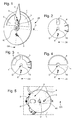
- the invention relates to a mobile assembly 24 for a clock display device 1.
- this mobile assembly 24 is constituted by, on the one hand, a display 2, such as a needle or the like, pivoting about the pivot axis D and having a first center of inertia 3 eccentric and positioned in a direction of unbalance DB relative to this pivot axis D, and secondly at least one mobile 4 pivoting about the same pivot axis D.
- This display 2 and this at least one mobile 4 are integral in pivoting about the pivot axis D.
- the at least one mobile 4 has a second center of inertia 5 positioned in the same unbalance direction DB relative to the pivot axis D, and the opposite side to that of the first center of inertia 3 with respect to the pivot axis D.
- this at least one mobile 4 comprises at least one cutout 6, which is entirely located on the opposite side to that of the second center of inertia 5 with respect to the pivot axis D, or / and at least one flyweight 60 entirely located on the side of this second center of inertia 5.
- the invention also relates to a display device 1 for a timepiece 100, comprising at least one such moving element 24.
- the mobile 4 has a toothing. More particularly, each mobile 4 has a toothing.
- At least one mobile 4 is devoid of toothing. More particularly, each mobile 4 is devoid of teeth.
- the mobile 4 is unique.
- the mobile 4 comprises a single cutout 6 located on the side opposite to that of the second center of inertia 5 with respect to the pivot axis D.
- the mobile 4 comprises two such cutouts 6 located on either side of an arm 7 located on the opposite side to the side of the second center of inertia 5 with respect to the pivot axis D.
- each such cutout 6 extends entirely on the side opposite to that of the second center of inertia 5 with respect to the pivot axis D.
- these two cutouts 6 each extend entirely on the opposite side to that of the second center of inertia 5 with respect to the pivot axis D.
- each mobile 4 is entirely symmetrical with respect to a plane passing through the pivot axis D and in the unbalance direction DB.
- the display device 1 comprises, facing each such mobile 4, detection means 8, which are arranged to detect discontinuities in the thickness of the mobile 4, in the direction of the axis of pivoting D.
- these detection means 8 comprise at least one electrode circuit 9 arranged to detect capacitive variations in the thickness of a mobile 4, that is, that is to say in the direction of the pivot axis D.
- the detection may be of inductive type, or other.
- the invention is realized in such a way that the angular position detection is carried out automatically when a battery 14 is placed in the movement of the watch, and so that, once the detection has been carried out, the 4 are movable angularly optimally before assembly of the displays 2, including needle hunting.
- This singularity passes, as visible on the figure 5 , above electrodes 9 made by tracks in a printed circuit 10.
- the singularity can be achieved in particular by a single opening 6 in a solid board as visible on the figure 2 or 4 , or by an arm 7 surrounded by empty areas as visible on the figure 3 .
- the openings 6 small hole of the figure 2 , large recesses of the Figures 3 and 4 , made in the mobile 4, cause a displacement of its center of gravity, creating an unbalance related to the amount of material removed.
- the counter-mass may comprise, or consist of, at least one component attached to the mobile 4, forming a flyweight 60, for example a half-disk or the like, entirely located on the side of the second center of inertia 5.
- a flyweight 60 for example a half-disk or the like
- Such configuration allows, if necessary, to further increase the unbalance, for example, as visible on the figure 6 , with a mobile 4 having one or more cutouts 6, and, in addition, a flyweight 60 reported in half-disk or the like.
- a flyweight 60 may be glued, crimped, or the like, or riveted or screwed with holding elements 61 such as rivets or screws.
- the invention favors an embodiment where the detection means are intrinsic to the display device 1, and do not require a test bench or the like, so as to allow after-sales interventions, with the removal and reassembly displays, including needles.
- these detection means are integrated in a plate, a bridge, or a printed circuit, the timepiece, including a watch.
- the display device 1 comprises, facing each such mobile 4, at least one printed circuit board 10 enclosing or supporting these detection means 8.
- detection means 8 are arranged to detect discontinuities of certain physical quantities during the pivoting of the mobile 4. They are connected to control means 11 which are arranged to perform the analysis of the signals sent by the detection means 8 to calculate, as the case, IIa median zone of an opening 6, or an array of openings 6, or an arm 7 located between two openings, or the like.
- control means 11 can be deported, they can also advantageously be integrated with the control device 1, and in particular with a printed circuit 10 when the control device 1 comprises.
- the display device 1 comprises control means 11, which are arranged to process information transmitted by the detection means 8, and detect the angular position of the unbalance direction DB.
- the control means 11 are advantageously arranged to control such motor means 12 to generate a pivoting movement of such a mobile 4, to align the unbalance direction DB, thus determined by the detection means 8, with a predetermined reference direction DR, for example at noon of the watch, with the second center of inertia 5 of mobile 4 at six o'clock, and the first center of inertia 3 of the display at twelve o'clock.
- the display device 1 comprises power supply means 13, battery 14, battery, or the like, which are arranged to feed in particular these control means 11, to detect the angular position of the unbalance direction. DB.
- These power supply means 13 are advantageously arranged to power such motor means 12, to generate a pivoting movement of such a mobile 4.
- the invention is also applicable to a mechanical watch
- the detection means 8 are then preferably interfaced with a mounting bench or the like, on which the alignment of the direction is carried out unbalance DB of the mobile 4 on a reference direction DR, which will then bring the display 2, including a needle pivotally secured to the mobile 4, in particular by driving.
- This interfacing is feasible, for example with an input-output of inductive sensors to an external measurement unit, or the like.
- the display 2 is a needle driven on a mobile 4, including but not limited to a gun 40 that includes the mobile 4, or on a tree on which is itself driven the mobile 4, or other.
- the invention also relates to a timepiece 100, in particular a watch, comprising at least one such display device 1.
- the invention also relates to a method of reducing the resulting unbalance, with respect to a common pivot axis D, of such a moving element 24 that includes a display device 1 clock.
- the display device 1 of motor means 12, which is controlled by the control means 11, is equipped to generate a pivoting movement of at least one mobile 4 to align the unbalance direction DB with the direction predetermined reference number DR.
- the display device 1 is equipped with power supply means 13 arranged to supply the control means 11 for detecting the angular position of the unbalance direction DB.
- the power supply means 12 are powered with these power supply means 13 to generate a pivoting movement of the at least one mobile 4.
- these power supply means 13 are made in the form of at least one battery 14, the introduction of which in the display device 1 triggers the detection of the angular position of the unbalance direction DB.
- the invention ensures automatic and optimal positioning of the mobiles before mounting or driving displays, including needles.
- This solution does not affect the aesthetic design of the hands of a watch: on the contrary, it allows the use of large unbalance needles, especially in gold, without requiring unsightly counter-mass on the needle itself.
- the unbalanced mobiles provide a double function: firstly precisely the replacement of the counter-masses of needles, and then the precise positioning of the unbalance direction, during detection, in particular capacitive.
- the invention is applicable to a plurality of coaxial needles, including center hands, the detection is then independently on each wheel.
Landscapes
- Physics & Mathematics (AREA)
- General Physics & Mathematics (AREA)
- Engineering & Computer Science (AREA)
- Manufacturing & Machinery (AREA)
- Electromechanical Clocks (AREA)
Priority Applications (6)
| Application Number | Priority Date | Filing Date | Title |
|---|---|---|---|
| EP15186726.4A EP3147726A1 (de) | 2015-09-24 | 2015-09-24 | Anzeigevorrichtung für uhr, die einen anzeiger mit starker umwucht umfasst |
| EP16178817.9A EP3147727B1 (de) | 2015-09-24 | 2016-07-11 | Anzeigevorrichtung für uhr, die einen anzeiger mit starker unwucht umfasst |
| US15/217,322 US10048651B2 (en) | 2015-09-24 | 2016-07-22 | Timepiece display device with high unbalance |
| JP2016156192A JP6437967B2 (ja) | 2015-09-24 | 2016-08-09 | 高い不均衡を有する時計表示デバイス |
| KR1020160116438A KR101946116B1 (ko) | 2015-09-24 | 2016-09-09 | 불균형이 큰 타임피스 디스플레이 디바이스 |
| CN201610846781.5A CN106557011B (zh) | 2015-09-24 | 2016-09-23 | 具有高不平衡性的钟表显示装置 |
Applications Claiming Priority (1)
| Application Number | Priority Date | Filing Date | Title |
|---|---|---|---|
| EP15186726.4A EP3147726A1 (de) | 2015-09-24 | 2015-09-24 | Anzeigevorrichtung für uhr, die einen anzeiger mit starker umwucht umfasst |
Publications (1)
| Publication Number | Publication Date |
|---|---|
| EP3147726A1 true EP3147726A1 (de) | 2017-03-29 |
Family
ID=54199061
Family Applications (2)
| Application Number | Title | Priority Date | Filing Date |
|---|---|---|---|
| EP15186726.4A Withdrawn EP3147726A1 (de) | 2015-09-24 | 2015-09-24 | Anzeigevorrichtung für uhr, die einen anzeiger mit starker umwucht umfasst |
| EP16178817.9A Active EP3147727B1 (de) | 2015-09-24 | 2016-07-11 | Anzeigevorrichtung für uhr, die einen anzeiger mit starker unwucht umfasst |
Family Applications After (1)
| Application Number | Title | Priority Date | Filing Date |
|---|---|---|---|
| EP16178817.9A Active EP3147727B1 (de) | 2015-09-24 | 2016-07-11 | Anzeigevorrichtung für uhr, die einen anzeiger mit starker unwucht umfasst |
Country Status (5)
| Country | Link |
|---|---|
| US (1) | US10048651B2 (de) |
| EP (2) | EP3147726A1 (de) |
| JP (1) | JP6437967B2 (de) |
| KR (1) | KR101946116B1 (de) |
| CN (1) | CN106557011B (de) |
Families Citing this family (1)
| Publication number | Priority date | Publication date | Assignee | Title |
|---|---|---|---|---|
| CN110262207B (zh) * | 2019-07-19 | 2024-07-30 | 深圳市雷诺表业有限公司 | 用于手表的表针结构及手表 |
Citations (5)
| Publication number | Priority date | Publication date | Assignee | Title |
|---|---|---|---|---|
| JPS52109851U (de) * | 1976-02-17 | 1977-08-20 | ||
| JPS5555275A (en) * | 1978-10-18 | 1980-04-23 | Citizen Watch Co Ltd | Assembling needle pointer |
| JPH05299667A (ja) | 1992-04-16 | 1993-11-12 | Toyota Autom Loom Works Ltd | 半導体装置 |
| JP2009300247A (ja) * | 2008-06-13 | 2009-12-24 | Casio Comput Co Ltd | 針取付構造、針取付制御装置、および時計 |
| JP2015114295A (ja) * | 2013-12-16 | 2015-06-22 | カシオ計算機株式会社 | 指針および時計 |
Family Cites Families (17)
| Publication number | Priority date | Publication date | Assignee | Title |
|---|---|---|---|---|
| US901822A (en) * | 1907-10-31 | 1908-10-20 | Fred Kuehn | Attachment for timepieces. |
| US940617A (en) * | 1909-03-17 | 1909-11-16 | Robert C Saloch | Clock. |
| US2920440A (en) * | 1957-02-20 | 1960-01-12 | Vernon G Ames | Flexible coupled seconds hand |
| JPS5555773U (de) * | 1978-10-12 | 1980-04-15 | ||
| DE69817764T2 (de) * | 1998-04-24 | 2004-07-15 | Asulab S.A. | Uhrwerk mit einem induktiven oder kapazitiven Sensor zur Detektion von mindestens einem Drehwinkel eines Zahnrades innerhalb des Uhrwerkes |
| CN1132077C (zh) * | 1999-05-06 | 2003-12-24 | 阿苏拉布股份有限公司 | 包括用于指示同轴模拟显示指针之角度位置的装置的钟表 |
| AU3077200A (en) * | 2000-01-24 | 2001-08-07 | Seiko Instruments Inc. | Electronic timepiece having indication hands |
| US7643381B2 (en) * | 2008-01-23 | 2010-01-05 | Sigelmann Rubens A | One-movement balanced hands clock |
| JP5281934B2 (ja) * | 2009-03-17 | 2013-09-04 | 本田技研工業株式会社 | 二輪車用メータ |
| CH701490A1 (fr) * | 2009-07-17 | 2011-01-31 | Franck Mueller Watchland S A | Tourbillon a roue d'echappement fixe. |
| JP5366319B2 (ja) * | 2009-09-14 | 2013-12-11 | セイコーインスツル株式会社 | デテント脱進機およびそれを有する機械式時計 |
| WO2011120180A1 (fr) * | 2010-04-01 | 2011-10-06 | Rolex S.A. | Dispositif de blocage pour roue dentée |
| CH703361A2 (fr) | 2010-06-22 | 2011-12-30 | Artisans Horlogers Sarl | Mouvement horloger presentant des fonctions de chronographe et de compte-a-rebours. |
| US9201398B2 (en) * | 2010-07-19 | 2015-12-01 | Nivarox-Far S.A. | Oscillating mechanism with an elastic pivot and mobile element for transmitting energy |
| JP5729665B2 (ja) * | 2010-09-14 | 2015-06-03 | セイコーインスツル株式会社 | 時計用デテント脱進機、および機械式時計 |
| JP5447900B1 (ja) * | 2012-08-30 | 2014-03-19 | カシオ計算機株式会社 | 指針 |
| JP6537014B2 (ja) * | 2015-03-17 | 2019-07-03 | カシオ計算機株式会社 | 指針および時計 |
-
2015
- 2015-09-24 EP EP15186726.4A patent/EP3147726A1/de not_active Withdrawn
-
2016
- 2016-07-11 EP EP16178817.9A patent/EP3147727B1/de active Active
- 2016-07-22 US US15/217,322 patent/US10048651B2/en active Active
- 2016-08-09 JP JP2016156192A patent/JP6437967B2/ja active Active
- 2016-09-09 KR KR1020160116438A patent/KR101946116B1/ko active Active
- 2016-09-23 CN CN201610846781.5A patent/CN106557011B/zh active Active
Patent Citations (5)
| Publication number | Priority date | Publication date | Assignee | Title |
|---|---|---|---|---|
| JPS52109851U (de) * | 1976-02-17 | 1977-08-20 | ||
| JPS5555275A (en) * | 1978-10-18 | 1980-04-23 | Citizen Watch Co Ltd | Assembling needle pointer |
| JPH05299667A (ja) | 1992-04-16 | 1993-11-12 | Toyota Autom Loom Works Ltd | 半導体装置 |
| JP2009300247A (ja) * | 2008-06-13 | 2009-12-24 | Casio Comput Co Ltd | 針取付構造、針取付制御装置、および時計 |
| JP2015114295A (ja) * | 2013-12-16 | 2015-06-22 | カシオ計算機株式会社 | 指針および時計 |
Also Published As
| Publication number | Publication date |
|---|---|
| JP6437967B2 (ja) | 2018-12-12 |
| KR101946116B1 (ko) | 2019-02-08 |
| EP3147727A1 (de) | 2017-03-29 |
| KR20170036611A (ko) | 2017-04-03 |
| US20170090423A1 (en) | 2017-03-30 |
| JP2017062227A (ja) | 2017-03-30 |
| CN106557011A (zh) | 2017-04-05 |
| US10048651B2 (en) | 2018-08-14 |
| CN106557011B (zh) | 2020-04-03 |
| EP3147727B1 (de) | 2018-10-31 |
Similar Documents
| Publication | Publication Date | Title |
|---|---|---|
| EP2132604B1 (de) | Tourbillon-uhrwerk | |
| EP2605079B1 (de) | Modulares Uhrwerk mit funktionellen Modulen | |
| EP2115536B1 (de) | Uhrwerk | |
| EP1445668B1 (de) | Schwungmasse | |
| CH704063B1 (fr) | Pièce d'horlogerie | |
| WO2001018611A1 (fr) | Indicateur de temps a regulation mecanique | |
| CH713109B1 (fr) | Mouvement d'horlogerie comportant aux moins deux tourbillons. | |
| EP2977833B1 (de) | Präzise Positionierung der Brücke einer Uhr | |
| EP2781972B1 (de) | Zapfen für Uhrwerksmechanismus | |
| EP2795409B1 (de) | Verfahren zur verbesserung der schwenkbarkeit eines mobilen geräts | |
| EP3147727B1 (de) | Anzeigevorrichtung für uhr, die einen anzeiger mit starker unwucht umfasst | |
| EP3502803B1 (de) | Regulierbare uhreneinheit | |
| EP2466397A1 (de) | Drehteil einer Uhr mit peripherem Antrieb | |
| CH711564B1 (fr) | Dispositif d'affichage d'horlogerie comportant un afficheur à fort balourd. | |
| CH703964A1 (fr) | Mouvement de montre automatique avec masse oscillante disposée du côté de la platine. | |
| EP3182218B1 (de) | Triebfeder einer uhr mit verbesserter sichtbarkeit für komplizierte armbanduhr | |
| WO2010142778A1 (fr) | Mecanisme de remontage automatique pour mouvement horloger | |
| CH714460A2 (fr) | Ensemble réglable d'horlogerie comportant un pont réglable. | |
| CH711927A2 (fr) | Mobile d'horlogerie à visibilité améliorée pour montre compliquée. | |
| CH713384B1 (fr) | Procédé de prise d'information mécanique dans un mouvement horloger, notamment pour indicateur de réserve de marche. | |
| BE554458A (fr) | Régulateur magnétique de marche pour l'horlogerie. | |
| EP0853264A2 (de) | Chronographuhr mit einem Mechanismus mit reduzierter Höhe | |
| CH705897A2 (fr) | Procédé d'amélioration du pivotement d'un mobile et mobile ou mobile équipé pour instrument scientifique ou garde-temps. |
Legal Events
| Date | Code | Title | Description |
|---|---|---|---|
| PUAI | Public reference made under article 153(3) epc to a published international application that has entered the european phase |
Free format text: ORIGINAL CODE: 0009012 |
|
| AK | Designated contracting states |
Kind code of ref document: A1 Designated state(s): AL AT BE BG CH CY CZ DE DK EE ES FI FR GB GR HR HU IE IS IT LI LT LU LV MC MK MT NL NO PL PT RO RS SE SI SK SM TR |
|
| AX | Request for extension of the european patent |
Extension state: BA ME |
|
| STAA | Information on the status of an ep patent application or granted ep patent |
Free format text: STATUS: THE APPLICATION HAS BEEN WITHDRAWN |
|
| 18W | Application withdrawn |
Effective date: 20170915 |