EP0952431A2 - Optischer Durchflussmengenmesser - Google Patents
Optischer Durchflussmengenmesser Download PDFInfo
- Publication number
- EP0952431A2 EP0952431A2 EP99303189A EP99303189A EP0952431A2 EP 0952431 A2 EP0952431 A2 EP 0952431A2 EP 99303189 A EP99303189 A EP 99303189A EP 99303189 A EP99303189 A EP 99303189A EP 0952431 A2 EP0952431 A2 EP 0952431A2
- Authority
- EP
- European Patent Office
- Prior art keywords
- light
- pipe
- optical
- lens
- delivery system
- Prior art date
- Legal status (The legal status is an assumption and is not a legal conclusion. Google has not performed a legal analysis and makes no representation as to the accuracy of the status listed.)
- Granted
Links
Images


Classifications
-
- G—PHYSICS
- G01—MEASURING; TESTING
- G01P—MEASURING LINEAR OR ANGULAR SPEED, ACCELERATION, DECELERATION, OR SHOCK; INDICATING PRESENCE, ABSENCE, OR DIRECTION, OF MOVEMENT
- G01P5/00—Measuring speed of fluids, e.g. of air stream; Measuring speed of bodies relative to fluids, e.g. of ship, of aircraft
- G01P5/18—Measuring speed of fluids, e.g. of air stream; Measuring speed of bodies relative to fluids, e.g. of ship, of aircraft by measuring the time taken to traverse a fixed distance
- G01P5/20—Measuring speed of fluids, e.g. of air stream; Measuring speed of bodies relative to fluids, e.g. of ship, of aircraft by measuring the time taken to traverse a fixed distance using particles entrained by a fluid stream
-
- G—PHYSICS
- G01—MEASURING; TESTING
- G01F—MEASURING VOLUME, VOLUME FLOW, MASS FLOW OR LIQUID LEVEL; METERING BY VOLUME
- G01F1/00—Measuring the volume flow or mass flow of fluid or fluent solid material wherein the fluid passes through a meter in a continuous flow
- G01F1/704—Measuring the volume flow or mass flow of fluid or fluent solid material wherein the fluid passes through a meter in a continuous flow using marked regions or existing inhomogeneities within the fluid stream, e.g. statistically occurring variations in a fluid parameter
- G01F1/708—Measuring the time taken to traverse a fixed distance
- G01F1/7086—Measuring the time taken to traverse a fixed distance using optical detecting arrangements
Definitions
- This invention relates to an optical flow meter system for measuring the flow of fluid in a pipeline.
- Obstruction meters determine flow rate in an indirect fashion by introducing a physical obstruction directly into the flow and measuring the influence of the obstruction. For example the pressure drop across a flow restriction is often measured and correlated with the flow rate. Examples of this approach include orifice meters, venturi meters and critical flow nozzles [ref. Experimental Methods For Engineers , Fourth Edition, McGraw-Hill Book Company, J.P. Holman and W.J. Gajda, Jr., Chapter Seven].
- Another example of an obstruction meter is the vortex meter, in which the obstruction causes vortex shedding.
- the shedding frequency is determined by means of strain sensors, thermal sensors, or pressure sensors. The shedding frequency increases with flow rate.
- Obstruction meters extract energy from the flow and are therefore inherently inefficient because additional pumping capacity is required to overcome the induced pressure drop.
- the physical obstruction also prevents the use of pipeline-pigs for maintenance and diagnostics. Component wear can cause a shift in the discharge coefficient or shedding frequency, and therefore regular maintenance of these devices is required.
- Pressure or load transducers are normally mounted next to the obstruction, and therefore local power is required. For pipelines transporting flammable or explosive fluids, appropriate explosion-proof enclosures are required for these transducers. Finally, these meters have a limited turndown ratio owing to the nonlinear relationship between flow rate and pressure drop.
- Kinematic type meters determine the flow rate by directly sensing the actual velocity using a turbine blade assembly that rotates kinematically with the flow.
- the rotational speed of the turbine is measured using a frequency pickup and is empirically related to the flow rate using an experimentally determined coefficient.
- These meters provide an output that is approximately proportional to volumetric flow rate and substantially independent of density.
- the primary disadvantages of this class of meter are the presence of moving parts, the obstruction to flow, the need for calibration, the requirement of electrical power and the physical size.
- the third class of meter relies on non-intrusive methods to determine flow rate.
- the ultrasonic flow meter is the only meter in this category that has been commercially developed for use in high pressure natural gas pipelines.
- the operating principle is to compare the upstream and downstream times of flight of an acoustic pulse from one transducer to another, which are located near the inside surface of the pipe.
- the flow is unrestricted and therefore these devices do not produce any significant pressure drop.
- these devices require a relatively long installation length, are limited to larger pipe sizes, can suffer from acoustic noise and are sensitive to swirl in the flow.
- flow rate may be determined by measuring the velocity of micron-sized particles suspended in a flow field. This is accomplished by determining the time-of-flight of these particles as they move between two discrete regions illuminated by laser light.
- This basic concept was proved by D.H. Thomson ["A Tracer Particle Fluid Velocity Meter Incorporating a Laser", Jour. of Sci. Inst. (J. Phys. E.) Series 2, Vol. 1,929-932 (1968)] using a large gas laser, Kosters prism, two convex lenses, an imaging lens and a photomultiplier.
- Figure 1 is a diagram of a commercial orifice meter fitting.
- Figure 2 is a schematic diagram of an optical meter according to this invention.
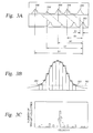
- Figure 3 illustrates the steps in processing the data from the device.
- Figure 4 is a schematic optical layout of a preferred embodiment of this invention with specific components.
- Figure 5 is a schematic diagram of a preferred form of a collection lens.
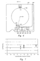
- Figure 6 is a diagram of a rigid plate which fits into an orifice meter and houses the optical system.
- Figure 7 is a plot of experimental results of the device.
- the present invention provides an optical device for generating a signal which contains information which may be used to describe the fluid flow on the basis of the motion of suspended particles contained in a fluid flowing through a pipeline, said device comprising: a narrow frequency light source; one or more optical delivery systems; one or more collectors which collect light scattered by particles in the flow; and one or more photo detectors.
- the optical delivery system(s) and collector(s) are contained within the pipeline.
- the device of the present invention generates signals based on the light scattered by particles flowing through a pipeline.
- the present invention further provides an optical device for generating information to determine the flow rate of a fluid within a pipe comprising in cooperating arrangement an orifice fitting having mounted therein a rigid plate.
- the rigid plate holds at least one optical delivery system providing at least two parallel beams of light and a collector receiving scattered light from particles in the fluid moving through the pipeline.
- the optical device of this invention contains two optical sub-systems, namely a "delivery” system and a “collection” system.
- the delivery system is designed to provide a parallel pair of light beams (preferably laser beams), separated by a known distance, through the center of a pipeline.
- the optical delivery system may comprise one or more of: a collimator, a light splitter and a focussing lens.
- the two beams are preferably perpendicular to the axis of the pipe, with one light (laser) beam located upstream of the other.
- the light beams are conditioned (focused) such that they are most intense at the location within the pipe that the measurement is to be made. Small particles suspended in the natural gas flow pass through the two beams, producing brief pulses of scattered light.
- the second optical sub-system which collects scattered light from a small region of interest.
- the optical sub-systems are aligned such that the optical collection region is coincident with the most intense regions of the light beams, which defines a localized measurement volume.
- the optical flow meter is invested into the pipeline either via an existing meter fitting or a new fitting. Most preferably, this is achieved by encasing critical elements of the optical flow meter in a housing which is adapted to an existing meter fitting.
- the present invention enables the use of an optical system to measure the flow of fluid in a pipeline, especially the flow of natural gas in a high pressure pipeline.
- the present invention further provides a process for measuring the flow rate of a fluid having entrained suspended particles through a pipe comprising comparing the timing of light scattering events from at least one light sheet in said pipe to the light scattering events from at least one other light sheet in said pipe using one of the devices described above and comparing the events from both light sheets to generate a histogram (called a corrologram) which has a characteristic peak corresponding to the flow rate.
- a histogram called a corrologram
- optical flow meter described herein is a robust device which may be used in a remote environment.
- a narrow frequency light source means a system that provides essentially monochromatic light having a wavelength preferably within a range of 50 nanometers (nm), most preferably within a range of 10 nm.
- the measurement volume is the location or locations where the sheet of light or beam of light is focused within the interior of the pipeline to detect particles passing through such location(s); particles scatter light from the optical delivery system and scattered light is gathered by the collector.
- the input for and output from the optical delivery system and collector communicate externally from the pipeline preferably via an optical transmission path, most preferably an optical fiber(s).
- the optical fiber(s) may be continuous or they may include appropriate coupling devices such as those sold by AT&T under the trademark ST connectors. However other means for providing input and receiving output from the device of the present invention would occur to those skilled in the art.
- the flow meter of the present invention may be installed in the pipeline, for example between adjacent flanges. However, such an installation is not easily removed for maintenance or servicing.
- the device is installed in a removable cooperating plate and fitting such as an orifice plate carrier and fitting.
- Figure 1 shows a cross section of a typical commercial orifice fitting.
- the standard orifice meter in the natural gas industry such as that shown in Figure 1 consists of a meter body 101 that permits the orifice plate 102 to be inserted into or removed from a high pressure pipe 103.
- the orifice plate 102 which is a round steel plate with a hole in the center, is fitted with a thick rubber gasket 104 around its circumference. This gasket provides a seal when the plate is in use to ensure that all of the flow passes through the central hole 105.
- the gasket and orifice plate fit into a larger rectangular "plate carrier" 106.
- the plate carrier is inserted into the body of the meter 101 through a closable opening 107 and holds the orifice plate 102 in place.
- the housing of the meter can generally be of two types: those that allow the plate to be inserted and removed while the system is under pressure; and those that require that the pipe be depressurized before the orifice plate can be removed.
- Figure 2 shows a preferred configuration of the optical flow meter.
- a narrow frequency light source 201 preferably a laser
- the energy emitted by the laser is transmitted to the meter via a single mode polarization maintaining optical fiber link 202 (i.e. an optical fiber).
- the optical fiber enters the body of the meter through a high-pressure fitting 203 accommodating both the transmission fiber and multi-mode receiving optical fiber 209.
- the transmission optical fiber terminates in a collimator 204.
- the beam exiting the collimator then passes through a beam splitting prism 205 to generate two beams, followed by a focusing lens 206 which produces parallel light beams 207 focused within the pipe typically at or adjacent to the centerline of the pipe for a single point measurement using two sheets of light.
- the parallel light beams are focused, that is they narrow to a waist at or within the measurement volume (and they diverge on each side of the measurement volume). This results in an intensely illuminated region at the light beam waist preferably a high intensity sheet of light (but it could also be a spot of light).
- Note that for any velocity measurement at a specific location at least two closely spaced sheets of light are required.
- the measurement volumes may be located at different positions within the cross-section of the pipe.
- a collection lens 208 which collection lens 208 is preferably a refractive doublet or diffractive/refractive doublet
- the receiving optical fiber 209 transmits the scattered light pulses back to a photo detector 210 (avalanche photodiode(s) or photo multiplier tube(s)) located near the laser.
- the electrical output from the photo-detector is analyzed in a signal processor unit 211 that correlates the optical pulses and determines flow rate at the measurement volume.
- Each particle that passes through the pair of light beams (or sheets) emits two pulses of scattered light, separated by an amount of time ⁇ t.
- ⁇ t the physical spacing between the two beams (S)
- Correlation techniques are used to analyze streams of pulses produced by numerous particles passing through the beams over a prescribed period of time. This technique eliminates the ambiguity that results from overlapping pulse pairs, plus it minimizes the influence of single pulse events which occur when a particle passes through only one of the two beams.
- One method of correlating high data rates is outlined in United States patent 4,887,213.
- Figure 3 shows a preferred method of calculating the velocity of a fluid.
- the figure consists of three components: a plot of output signal versus time (a); the process of digitizing an individual pulse (output) (b); and a histogram (corrologram) of transit velocities (c). The relationship between these three aspects of the velocity calculation are described below.
- the signals are generated by the device, with a characteristic lag between events (detection of scattered light) on the upstream and downstream channels (e.g. photo detectors).
- Each of these pulses is digitized when a certain threshold 301 (e.g. exceeding the background noise) is exceeded as shown in (b).
- the time that the pulse occurred has to be identified for each pulse.
- the time of occurrence (temporal centroid) is determined, either by midpoint between the time when the signal exceeds the threshold 302 and when the signal falls below the threshold 303, or by a weighted average of the digitized pulse shape, as shown in Figure 3(b).
- the time and amplitude of the pulses are stored for later reference.
- Each pulse that occurred on the downstream channel (e.g. 305) is compared to previous pulses that occurred on the upstream channel 306 (limited by a time which is equal to or greater than the transit time for the minimum detectable velocity) to generate a series of potential transit times ⁇ t for each down stream pulse.
- Each transit time is converted into a possible transit velocity by dividing the beam spacing by the transit time.
- This series of potential transit velocities are accumulated and stored in a histogram called a corrologram, such as that shown in Figure 3(c).
- the corrologram shows the number of possible transit velocities that lie in a narrow range called a "bin".
- the number of events in each bin is represented by the bars in Figure 3(c).
- the average transit velocity can be determined by the average of the velocities in the most populated bin (and the appropriate number of neighboring bins).
- This method can be generalized to the case where both pulses are generated by the same detector. In this case all pulses are considered as possible upstream and downstream pulses (since the upstream and downstream information is indistinguishable), and the corrologram still shows a characteristic transit velocity.
- the present invention seeks to provide a process for determining the velocity of a fluid moving through a pipe comprising converting the electrical signals generated by a device according to the invention comprising:
- the light source and the photodiode are external to the pipe; however a preferred embodiment of the invention requires that the optical lenses be located within the pipe.
- the advantage of placing the optical lenses inside the pipe is that for high pressure applications, windows are not required, and the optical system is confined to the inside of the pipe thereby reducing the safety issues associated with exposed laser light sources.
- the use of optical fiber also means that the electronics and processing system may be located many hundreds of meters from the actual measurement location. Additional advantages of the optical device of this invention include: (a) it does not introduce a pressure drop in the pipeline; (b) it may require less than five centimeters of pipe length for installation; and (c) it does not have moving parts that can wear over time.
- the device is fully compatible with a range of pipeline environments including high-pressure natural gas. Furthermore, no electrical supply is required at the meter location.
- optical device described above may be constructed using a number of alternative components and each of these individual configurations may be installed in various mechanical housings.
- One preferred embodiment described below is tailored to be installed in a standard orifice plate carrier housing used in natural gas pipeline systems. This embodiment is particularly attractive to those users who have many orifice fittings already installed in the field.
- Figure 4 shows the optical components used in a preferred design of a plate that replaces the plate carrier, and Table 1 provides a detailed description of each component.
- Table 1 Optical Components in Figure 4 Item # Description Supplier Model / Part Number 401 150 mW Laser (830 nm) SDL SDL-5421-G1 402 Laser current driver Seastar LD 1000 404 Laser/fiber coupler OZ Optics LDPC-02-830-5/125-P-40 407 High pressure pass-through fitting PAVE Technology Inc.
- Melles Griot 01 LCP 001 or 01 LCP 005 413 Cemented doublet 15 mm diameter NOVA designed, built by Lumonics Optics 414 Collection fibers (multimode) NA 0.22, low OH - Thor Labs (3M product) FG-200-LCR 415 SMA connectors Thor Labs 10230A 416 High pressure pass-through fitting PAVE Technology Inc. PT-SS-150-FG200- 417 Silicone Avalanche Photo Diode (APD) with transimpedance amplifier EG&G Optoelectronics C30657-010-QC-06
- Light energy is provided by a 150 mW near-infrared diode laser 401 (such as that sold by SDL Inc. (San Jose, CA)), driven by a laser current supply (402) such as that sold by Seastar Optics Inc. (Sidney, BC) that is connected to diode laser 401 by an electrical cable 403.
- the laser diode is directly pigtailed to polarization-maintaining fiber (405) using laser to fiber coupler (404), such as that sold by OZ Optics Ltd. (Carp, ON).
- the fiber enters the high pressure housing (406) through a pressure fitting (407) such as those sold by PAVE Technology Co. Inc. (Dayton, Ohio).
- FC polarization maintaining connector (408) is located on either side of the bulkhead such that the individual assemblies can be easily separated.
- the light energy exiting the fiber 405 is collimated into a uniform laser beam using a collimator 409 (which uses a 0.25 pitch GRIN lens) such as those sold by Oz Optics Ltd.
- the collimator has a small vent hole to prevent damage to the optical fitting under pressure.
- the beam is then split into two beams using a Wollaston prism 410 such as those sold by Karl Lambrecht Corp. (Chicago IL). If required by space restrictions, the two beams may reflect off a planar mirror towards a cylindrical lens 411, otherwise the two beams project directly to the cylindrical lens 411.
- the cylindrical lens refracts the beams such that they become parallel.
- the cylindrical lens also focuses each of the beams such that two high intensity laser sheets are produced in the measurement volume 412. This may be at a distance of approximately 50 mm from the lens.
- Scattered light caused by particles passing through the waist regions of the two sheets, is collected and focused onto the ends of two 200 micron multi-mode optical fibers 414 by a specialized collection lens 413.
- This lens is preferably designed to prevent variations in refractive index from altering the focal length of the collection optics. (A detailed description of a novel collection lens is provided in the next section.)
- the multi-mode optical fibers pass through a second pressure fitting 416 as described above with SMA 905 connectors 415 on either side for easy removal.
- the collected light energy is transmitted by the multi-mode fibers 414 to a pair of avalanche photodiodes with built-in transimpedance amplifiers 417 such as those manufactured by EG&G Canada Ltd., Optoelectronics Division.
- the voltage outputs from the photodiodes are digitized and processed to determine particle velocity.
- Typical imaging systems use a lens which refracts light passing through it to form an image of the object at the desired location.
- Refraction occurs when light rays pass from the external medium (usually air) to the lens material (usually glass) or vice versa.
- Refraction, or the amount of bending of the light rays depends on the index of refraction of the two media in contact, and is governed by Snell's Law.
- the index of refraction of the surrounding medium can change significantly, then the performance of the optical system will depend on the external medium.
- the surrounding medium could be air at atmospheric pressure, a high pressure gas, or a liquid.
- the optical system To successfully image particles inside a high pressure natural gas environment such as a pipeline, the optical system must work correctly at the full range of pipeline pressures without adjustment. For practical purposes the system should also work at atmospheric conditions to facilitate the initial setup and testing. Any mechanical adjustment of optical alignment to compensate for the changes in refractive index of the gas in the pipe would normally be very difficult to perform inside the pressure-containing vessel and would have to be done continuously to account for changes in gas pressure and temperature and composition.
- the preferred collection lens images a particle to an aperture independently of the index of refraction of the surrounding medium.
- a light detector is located behind the aperture.
- the collection lens should also meet the following constraints.
- the object and image should be small relative to the lens.
- the object and image should be near the optical axis of the lens.
- the object (e.g. the particulate in the measurement volume) and its image should be at specifically defined locations.
- the position of the object is restricted.
- the wavelength of light is fixed.
- This performance may be achieved in a lens having concave first and last surfaces which are defined by spheres centered at the object and image locations respectively. All refraction of the light as it passes from the object to the image occurs internal to the lens.
- the lens has the appropriate light refraction to be consistent with the object and image location. If the above criteria are met the lens will ensure that all rays from the object enter the first surface at a perpendicular and leave the last surface at a perpendicular, hence there will be no refraction at the surface in contact with the surrounding medium.
- the light from the image is directed to the detector or an optical fiber feeding the detector.
- the internal refraction of light can be achieved by a number of methods including using: a material with a radial gradient in the index of refraction; a sealed air or gas space between the elements; a sealed liquid between the elements; a cemented doublet with two materials of differing index of refraction; a cemented lens of more than two elements; or a combination of the above.
- the preferred embodiment of the collection lens consists of a cemented doublet with two different materials with a large difference in refractive index and high transmission at the wavelength(s) of light of interest.
- Figure 5 shows the preferred lens 501 comprising a low index of refraction material 502 and a high index of refraction material 503.
- the high and low index of refraction materials are cemented together over a continuous surface 505 which may or may not be spherical.
- the surface of the low index of refraction material facing the object 504 (e.g. the particle scattering light) has a radius of curvature so that light scattered by particles strikes the surface facing the particles normally (at right angles).
- the external surface of the high index of refraction material 503 faces the detector 506 (or optical fiber leading to the detector) and has a radius of curvature so that point 506 is at the center of a sphere defined by the radius of curvature.
- the preferred collector lens eliminates sensitivities to the index of refraction of the surrounding fluid which will vary with temperature, pressure, and composition of the fluid.
- the cylindrical lens in the delivery system is made insensitive to the index of refraction of the surrounding fluid by use of a cylindrical doublet using the principles described above. That is, the light strikes at normal incidence (90°) at any lens surface where the surrounding fluid is in contact with the lens.
- the optical device of the present invention is constructed such that it is mounted within a rigid plate and installed within a standard orifice fitting. .
- a plate is illustrated in Figure 6 showing the location of the principal components.
- the plate carrier and orifice plate is replaced by a single plate 601 with a central hole 602 that preferably matches the inside diameter of the pipe.
- the optics of this invention are mounted in the plate 601 itself and the plate would be raised and lowered in the same manner as a standard plate carrier.
- the plate therefore provides a rigid, pre-aligned assembly that can be easily inserted into the orifice fitting.
- the optical fiber which delivers light from the light source fits in a slot 603 in the plate.
- the fiber terminates at the collimator 604 which is held in a slot 606 by supports 605 which are designed to be adjustably positioned in the slot 606.
- the light leaving the collimator 604 strikes the Wollaston prism 607 and is split into two beams.
- the beams of light reflect off a mirror 608 and are focussed and made parallel by a cylindrical lens 609 which is held in place by adjustable supports 605.
- the beams are focussed to a waist at the center of the pipe where the (small) measurement volume 610 is located.
- Light scattered by particles passing through the measurement volume 610 is collected by a refractive doublet 611 which is insensitive to the index of refraction of the surrounding fluid.
- the light is focussed to an image point 612 and enters one of two optical fibers leading to the detectors.
- One fiber receives the image of the upstream sheet of light and the other fiber receives the image of the downstream sheet of light.
- the angle between the optical delivery system and the collector may be any angle, including 180°, or direct backscatter. However, a particularly preferred angle is in the range of 5° to 25° from forward scatter.
- the orifice fitting has several threaded holes in the body for pressure measurement and optional crank handle locations. These holes provide locations for the high pressure fiber optic pass-through fittings to be installed, thereby providing the necessary optical communication between the internal and external components. Installation of the optical system within the orifice fitting has the advantages of providing highly rangeable measurement with virtually zero pressure drop, without the expense and time of having to modify the existing piping.
- the flow rate is determined by the product of the centerline velocity and a coefficient which ranges from between about 0.5 for fully laminar flow and about 0.86 for fully turbulent flow.
- the value of the coefficient is a function of the pipe Reynolds number and pipe roughness and can be determined from an empirical expression [ref. White, Frank M., "Fluid Mechanics", 2nd ed. McGraw Hill 1986, p.310].
- a geometry specific correlation must be used to determine the average velocity from the measured centerline value.
- the total flow rate through the pipe is determined using measurements at five points located in the pipe cross-section. Most preferably, these five points are located, according to the locations specified by Frank, Heilmann and Siekmann. One point is located at the center of the pipe, and the other four points are located a distance of 0.762R from the center, where R is the radius of the pipe. Further, these four points are spaced equally around the circumference of a circle with radius 0.762R. These locations are designated subscripts: 0 for the center point, and 1, 2, 3 and 4 for the remaining four points.
- a ratio a u is determined according to the following formula: where v is the velocity at each location designated by the subscript.
- a u is used to select a center-point correction factor a v from the following table: Criteria Center-point factor, a v a u ⁇ 0.86 0.8941 0.86 > a u ⁇ 0.83 0.8526 0.83 > a u ⁇ 0.80 0.8167 0.80 > a u 0.7575
- the Optical Flow Meter described here can easily be extended to permit the measurement of velocities at multiple points, and therefore flow rate measurements can be obtained with the proposed device in ill-conditioned flows.
- Multiple measurement volumes may be accomplished mechanically by multiple implementations of the single point techniques described above (i.e. multiple sets of delivery and collection systems).
- optical systems may also be used to generate multiple measurement volumes using a single optical element. This may be done for example using a prerecorded hologram or by using a manufactured diffractive optical element (e.g. a diffraction grating). Diffractive or holographic optical elements may also be used to collect light from the multiple measurement volumes.
- optical flow meter of the present invention is illustrated by the following non-limiting example.
- a NOVA 50E perforated plate flow conditioner was located 42 D (pipe diameters) upstream of the device to ensure a known and repeatable fully developed flow profile. Extensive measurements taken using pitot tubes and hot film anemometers have shown that the peak velocity (centerline) of a fully developed profile under the test conditions is 1.16 times the average velocity. Development of the NOVA 50E flow conditioner is explained in reference: Kamik, U., "A compact orifice meter/flow conditioner package", 3 rd Intemational Symposium on Fluid Flow Measurement, March 20-22, 1995.
- the average velocity was varied between 10 and 25 m/sec.
- the centerline velocity measurement obtained with the optical flow meter was compared to a predicted centerline velocity based on the orifice meter data, the shape of the velocity profile that is produced by the flow conditioner, and the temperature, pressure and gas composition measurements. Temperature and static pressure readings were taken at the measurement location to allow accurate determination of gas density, and also the index of refraction. The total uncertainty in the reference velocity was estimated at ⁇ 0.6%.
- Figure 7 shows the data obtained over a two-day period of testing.
- each point is a data point for one velocity measurement.
- the ordinate (Y axis) shows the deviation of the optical measurement from the reference orifice meter.
- Figure 7 shows good overall agreement for the velocities obtained using the reference system and the optical flow meter of the present invention.
Landscapes
- Physics & Mathematics (AREA)
- General Physics & Mathematics (AREA)
- Fluid Mechanics (AREA)
- Engineering & Computer Science (AREA)
- Aviation & Aerospace Engineering (AREA)
- Measuring Volume Flow (AREA)
- Investigating Or Analysing Materials By Optical Means (AREA)
Applications Claiming Priority (2)
| Application Number | Priority Date | Filing Date | Title |
|---|---|---|---|
| US65364 | 1998-04-23 | ||
| US09/065,364 US6128072A (en) | 1998-04-23 | 1998-04-23 | Optical flow meter integrally mounted to a rigid plate with direct optical access to the interior of a pipe |
Publications (3)
| Publication Number | Publication Date |
|---|---|
| EP0952431A2 true EP0952431A2 (de) | 1999-10-27 |
| EP0952431A3 EP0952431A3 (de) | 1999-12-01 |
| EP0952431B1 EP0952431B1 (de) | 2004-10-13 |
Family
ID=22062199
Family Applications (1)
| Application Number | Title | Priority Date | Filing Date |
|---|---|---|---|
| EP99303189A Expired - Lifetime EP0952431B1 (de) | 1998-04-23 | 1999-04-23 | Optischer Durchflussmengenmesser |
Country Status (4)
| Country | Link |
|---|---|
| US (2) | US6128072A (de) |
| EP (1) | EP0952431B1 (de) |
| CA (1) | CA2269299A1 (de) |
| DE (1) | DE69921009T2 (de) |
Cited By (6)
| Publication number | Priority date | Publication date | Assignee | Title |
|---|---|---|---|---|
| EP1205736A3 (de) * | 2000-10-10 | 2004-07-07 | General Electric Company | System und Verfahren zur, die Strömung nicht beeinflussenden, direkten Messung eines korrigierten Luft-Durchflusses |
| WO2006067513A1 (en) * | 2004-12-24 | 2006-06-29 | Campbell Scientific Limited | A weather measurement device for determining the falling speed of hydrometers |
| EP1849014A4 (de) * | 2004-12-17 | 2011-05-04 | Photon Control Inc | Optisches sendezeit-velocimeter |
| WO2020178641A1 (en) | 2019-03-07 | 2020-09-10 | Flowlit Ltd. | Optical fluid flow velocity measurement |
| EP3812712A1 (de) * | 2019-10-21 | 2021-04-28 | Universität der Bundeswehr München | Flüssigkeitsflussanalyse |
| US11953358B2 (en) | 2018-09-24 | 2024-04-09 | Promecon Process Measurement Control Gmbh | Method and device for measuring a flow velocity of a gas stream |
Families Citing this family (31)
| Publication number | Priority date | Publication date | Assignee | Title |
|---|---|---|---|---|
| US6510836B2 (en) * | 2000-07-03 | 2003-01-28 | Murad M. Ismailov | Swirl injector for internal combustion engine |
| US6510842B2 (en) * | 2000-07-03 | 2003-01-28 | Murad M. Ismailov | Flow meter |
| US6429926B1 (en) * | 2001-01-08 | 2002-08-06 | Nova Gas Transmission Ltd. | Optical flow meter capable of operating with a variable refractive index |
| GB2391304B (en) * | 2002-07-16 | 2004-09-15 | Paul Crudge | Flow meter |
| US7453569B2 (en) | 2002-07-31 | 2008-11-18 | Jan Arwood Northby | Method and apparatus for measuring particle motion using scattered radiation |
| US7012688B2 (en) * | 2002-07-31 | 2006-03-14 | Jan Arwood Northby | Method and apparatus for measuring particle motion optically |
| CA2439242C (en) * | 2003-09-03 | 2008-01-29 | Photon Control Inc. | Optical flow meter for measuring gases and liquids in pipelines |
| US6837113B1 (en) | 2003-09-05 | 2005-01-04 | Daniel Industries, Inc. | Enhanced velocity estimation in ultrasonic flow meters |
| US7831009B2 (en) * | 2003-09-25 | 2010-11-09 | Siemens Medical Solutions Usa, Inc. | Tantalum water target body for production of radioisotopes |
| WO2007106232A2 (en) * | 2006-02-27 | 2007-09-20 | Fluidnet Corporation | Volume measurement using gas laws |
| US10010686B2 (en) | 2006-02-27 | 2018-07-03 | Ivenix, Inc. | Fluid control system and disposable assembly |
| WO2007098265A2 (en) * | 2006-02-27 | 2007-08-30 | Fluidnet Corporation | Flow sensor calibrated by volume changes |
| US20110028937A1 (en) * | 2006-02-27 | 2011-02-03 | Fluidnet Corporation | Automated fluid flow control system |
| JP4129881B2 (ja) * | 2006-04-20 | 2008-08-06 | 株式会社オーバル | 防爆高温対応形マルチ渦流量計 |
| US20070277530A1 (en) * | 2006-05-31 | 2007-12-06 | Constantin Alexandru Dinu | Inlet flow conditioner for gas turbine engine fuel nozzle |
| US7782461B1 (en) * | 2007-04-05 | 2010-08-24 | Massey Sean J | Flow rate measuring device |
| US8858787B2 (en) * | 2007-10-22 | 2014-10-14 | Baxter International Inc. | Dialysis system having non-invasive fluid velocity sensing |
| US7823462B2 (en) * | 2007-12-14 | 2010-11-02 | Cameron International Corporation | Turbulence conditioner for transit time ultrasonic flow meters and method |
| US7847276B2 (en) * | 2008-03-14 | 2010-12-07 | Fluidnet Corporation | Impulse analysis for flow sensor-based fluid control system |
| US7895882B2 (en) * | 2008-03-14 | 2011-03-01 | Fluidnet Corporation | Density analysis for flow sensor-based fluid control system |
| US7894061B2 (en) * | 2008-06-19 | 2011-02-22 | Qorex Llc | Polarization based fiber optic downhole flowmeter |
| US20100235117A1 (en) * | 2009-03-15 | 2010-09-16 | Lauris Technologies Inc | Optical Gas Flow Meter |
| US8438936B2 (en) | 2011-06-03 | 2013-05-14 | General Electric Company | Sensor assembly including a collar for mounting sensors to a pipeline |
| FI122997B (fi) | 2011-09-06 | 2012-09-28 | Janesko Oy | Menetelmä ja sovitelma optisesti epähomogeenisen aineen virtausnopeuden mittaamiseksi |
| US8950188B2 (en) | 2011-09-09 | 2015-02-10 | General Electric Company | Turning guide for combustion fuel nozzle in gas turbine and method to turn fuel flow entering combustion chamber |
| US9032815B2 (en) | 2011-10-05 | 2015-05-19 | Saudi Arabian Oil Company | Pulsating flow meter having a bluff body and an orifice plate to produce a pulsating flow |
| US9068873B2 (en) | 2012-02-14 | 2015-06-30 | King Fahd University Of Petroleum And Minerals | Multiphase flow measurement system and method |
| US8960017B2 (en) * | 2012-11-14 | 2015-02-24 | Daniel Measurement And Control, Inc. | System and method for ultrasonic metering using an orifice meter fitting |
| US10318904B2 (en) | 2016-05-06 | 2019-06-11 | General Electric Company | Computing system to control the use of physical state attainment of assets to meet temporal performance criteria |
| CA3051376C (en) | 2019-08-06 | 2020-04-28 | Surface Solutions Inc. | Methane monitoring and conversion apparatus and methods |
| DE102019217470B3 (de) * | 2019-11-12 | 2021-02-04 | Universität Stuttgart | Verfahren zum Ermitteln eines Istwerts und/oder eines Istwertbereichs wenigstens einer Zustandsgröße eines Fluids in einer Fluidströmung mittels wenigstens eines Indikatorpartikels, Verfahren zum Betreiben einer fluidführenden Einrichtung, Indikatorpartikel sowie Einrichtung zum Ermitteln des Istwerts der wenigstens einen Zustandsgröße |
Family Cites Families (22)
| Publication number | Priority date | Publication date | Assignee | Title |
|---|---|---|---|---|
| GB302431A (en) * | 1927-10-05 | 1928-12-20 | Vickers Ltd | Improvements in or relating to variable delivery pumps |
| GB1542420A (en) * | 1976-09-04 | 1979-03-21 | Rolls Royce | Apparatus for laser anemometry |
| DE2643616C3 (de) * | 1976-09-28 | 1979-05-31 | Erwin Sick Gmbh Optik-Elektronik, 7808 Waldkirch | Strömungsgeschwindigkeitsmeßgerät |
| US4251733A (en) * | 1978-06-29 | 1981-02-17 | Hirleman Jr Edwin D | Technique for simultaneous particle size and velocity measurement |
| GB2116699B (en) * | 1982-03-02 | 1985-08-29 | Itt Ind Ltd | Fluid flowmeter |
| DE3347092A1 (de) * | 1983-12-24 | 1985-07-18 | MTU Motoren- und Turbinen-Union München GmbH, 8000 München | Verfahren und vorrichtung zur optischen messung der stroemung eines fluids |
| US4664513A (en) * | 1984-09-25 | 1987-05-12 | Cornell Research Foundation, Inc. | Multidimensional vorticity measurement optical probe system |
| DE3631900A1 (de) * | 1986-09-19 | 1988-04-07 | Deutsche Forsch Luft Raumfahrt | Vorrichtung zur messung von stroemungsvektoren in gasstroemungen |
| DE3712153C1 (de) * | 1987-04-10 | 1988-07-14 | Deutsche Forsch Luft Raumfahrt | Verfahren zur Messung von Stroemungsvektoren in Gasstroemungen |
| US4887213A (en) * | 1987-07-31 | 1989-12-12 | The Titan Corporation | System for, and methods of, providing for a determination of the movement of an airborne vehicle in the atmosphere |
| US4989969A (en) * | 1988-06-30 | 1991-02-05 | Hughes Danbury Optical Systems, Inc. | Time of flight velocimeter |
| US4978863A (en) * | 1988-09-06 | 1990-12-18 | The Dow Chemical Company | Method and apparatus for fiber optic backscattered light measurement to determine flow rates of multi-phase streams |
| US5046840A (en) * | 1988-12-19 | 1991-09-10 | The Titan Corporation | Improvements in a system for determining atmospheric data relating to the movements of an airborne vehicle |
| GB2231221B (en) * | 1989-05-06 | 1993-06-16 | Rolls Royce Plc | A method of measuring the three dimensional velocity components of a particle in a fluid flow |
| US5000566A (en) * | 1990-01-05 | 1991-03-19 | Lockheed Sanders, Inc. | Optical velocimeter |
| US5131741A (en) * | 1991-12-09 | 1992-07-21 | Zweben Ronald J | Refractive velocimeter apparatus |
| US5313263A (en) * | 1992-08-21 | 1994-05-17 | The Titan Corporation | System for, and method of, determining the speed of an airborne vehicle |
| US5365326A (en) * | 1993-02-12 | 1994-11-15 | The Dow Chemical Company | Method and apparatus for determining flow rates and concentrations in multi-phase streams |
| DE4443069C2 (de) * | 1994-12-03 | 1997-01-16 | Deutsche Forsch Luft Raumfahrt | Verfahren zur Messung von Strömungsvektoren in Gasströmungen |
| US5701172A (en) * | 1995-06-07 | 1997-12-23 | Gas Research Institute | Optical flowmeter |
| JPH09304535A (ja) * | 1996-05-09 | 1997-11-28 | Omron Corp | 計測装置および方法 |
| US5865871A (en) * | 1996-10-01 | 1999-02-02 | Laser Metric, Inc. | Laser-based forward scatter liquid flow meter |
-
1998
- 1998-04-23 US US09/065,364 patent/US6128072A/en not_active Expired - Fee Related
-
1999
- 1999-04-16 CA CA002269299A patent/CA2269299A1/en not_active Abandoned
- 1999-04-23 DE DE69921009T patent/DE69921009T2/de not_active Expired - Fee Related
- 1999-04-23 EP EP99303189A patent/EP0952431B1/de not_active Expired - Lifetime
-
2000
- 2000-03-15 US US09/526,326 patent/US6275284B1/en not_active Expired - Fee Related
Cited By (7)
| Publication number | Priority date | Publication date | Assignee | Title |
|---|---|---|---|---|
| EP1205736A3 (de) * | 2000-10-10 | 2004-07-07 | General Electric Company | System und Verfahren zur, die Strömung nicht beeinflussenden, direkten Messung eines korrigierten Luft-Durchflusses |
| EP1849014A4 (de) * | 2004-12-17 | 2011-05-04 | Photon Control Inc | Optisches sendezeit-velocimeter |
| NO337240B1 (no) * | 2004-12-17 | 2016-02-22 | Photon Control Inc | Optisk transittid-hastighetsmåler |
| WO2006067513A1 (en) * | 2004-12-24 | 2006-06-29 | Campbell Scientific Limited | A weather measurement device for determining the falling speed of hydrometers |
| US11953358B2 (en) | 2018-09-24 | 2024-04-09 | Promecon Process Measurement Control Gmbh | Method and device for measuring a flow velocity of a gas stream |
| WO2020178641A1 (en) | 2019-03-07 | 2020-09-10 | Flowlit Ltd. | Optical fluid flow velocity measurement |
| EP3812712A1 (de) * | 2019-10-21 | 2021-04-28 | Universität der Bundeswehr München | Flüssigkeitsflussanalyse |
Also Published As
| Publication number | Publication date |
|---|---|
| CA2269299A1 (en) | 1999-10-23 |
| EP0952431A3 (de) | 1999-12-01 |
| DE69921009T2 (de) | 2005-10-20 |
| US6128072A (en) | 2000-10-03 |
| US6275284B1 (en) | 2001-08-14 |
| EP0952431B1 (de) | 2004-10-13 |
| DE69921009D1 (de) | 2004-11-18 |
Similar Documents
| Publication | Publication Date | Title |
|---|---|---|
| EP0952431B1 (de) | Optischer Durchflussmengenmesser | |
| US7265832B2 (en) | Optical flow meter for measuring gases and liquids in pipelines | |
| Durst | Combined measurements of particle velocities, size distributions, and concentrations | |
| US5701172A (en) | Optical flowmeter | |
| Liu et al. | Novel multifunctional optical‐fiber probe: I. Development and validation | |
| US5999256A (en) | Particle measurement system | |
| US20080231860A1 (en) | Optical Device and Method for Sensing Multiphase Flow | |
| US3809480A (en) | Method and apparatus for surveying the velocities of a flow field | |
| US3547540A (en) | Laser fluid velocity detector | |
| NO337240B1 (no) | Optisk transittid-hastighetsmåler | |
| US3623361A (en) | Optical probing of supersonic flows with statistical correlation | |
| US6429926B1 (en) | Optical flow meter capable of operating with a variable refractive index | |
| US6050656A (en) | Optical based opacity and flow monitoring system and method of monitoring opacity and flow | |
| US5090801A (en) | Laser velocimeter for near-surface measurements | |
| Alekseenko et al. | Measurements of the liquid-film thickness by a fiber-optic probe | |
| Gartrell et al. | A Scanning laser-velocimeter technique for measuring two-dimensional wake-vortex velocity distributions | |
| CN114264343A (zh) | 一种流体传输激光脉冲衰减系数与流量函数的构建方法 | |
| Bates | Anemometers (Laser Doppler) | |
| Yokoi et al. | Polarized-type phase Doppler method for simultaneous measurements of particle velocity, diameter, and refractive index | |
| Ivanov et al. | Measurement of the velocity profile in liquid streams of large volumes using a laser Doppler velocimeter | |
| Tjin et al. | New side-projected fiber optic probe for in vivo flow measurements | |
| Achimastos et al. | Recent developments in nonintrusive measuring techniques for particle velocity and size measurements | |
| Johnson | Laser velocimeter for near-surface measurements | |
| AZZAZY | Development of an optical volumetric flowmeter(Final Report, Apr. 1985-Mar. 1989) | |
| Nova | Department of Chemical and Biochemical Engineering |
Legal Events
| Date | Code | Title | Description |
|---|---|---|---|
| PUAI | Public reference made under article 153(3) epc to a published international application that has entered the european phase |
Free format text: ORIGINAL CODE: 0009012 |
|
| PUAL | Search report despatched |
Free format text: ORIGINAL CODE: 0009013 |
|
| AK | Designated contracting states |
Kind code of ref document: A2 Designated state(s): BE DE ES FR GB IT NL |
|
| AX | Request for extension of the european patent |
Free format text: AL;LT;LV;MK;RO;SI |
|
| AK | Designated contracting states |
Kind code of ref document: A3 Designated state(s): AT BE CH CY DE DK ES FI FR GB GR IE IT LI LU MC NL PT SE |
|
| AX | Request for extension of the european patent |
Free format text: AL;LT;LV;MK;RO;SI |
|
| RTI1 | Title (correction) |
Free format text: OPTICAL FLOW METER |
|
| RTI1 | Title (correction) |
Free format text: OPTICAL FLOW METER |
|
| 17P | Request for examination filed |
Effective date: 20000526 |
|
| AKX | Designation fees paid |
Free format text: BE DE ES FR GB IT NL |
|
| 17Q | First examination report despatched |
Effective date: 20031112 |
|
| GRAP | Despatch of communication of intention to grant a patent |
Free format text: ORIGINAL CODE: EPIDOSNIGR1 |
|
| GRAS | Grant fee paid |
Free format text: ORIGINAL CODE: EPIDOSNIGR3 |
|
| GRAA | (expected) grant |
Free format text: ORIGINAL CODE: 0009210 |
|
| AK | Designated contracting states |
Kind code of ref document: B1 Designated state(s): BE DE ES FR GB IT NL |
|
| PG25 | Lapsed in a contracting state [announced via postgrant information from national office to epo] |
Ref country code: NL Free format text: LAPSE BECAUSE OF FAILURE TO SUBMIT A TRANSLATION OF THE DESCRIPTION OR TO PAY THE FEE WITHIN THE PRESCRIBED TIME-LIMIT Effective date: 20041013 Ref country code: IT Free format text: LAPSE BECAUSE OF FAILURE TO SUBMIT A TRANSLATION OF THE DESCRIPTION OR TO PAY THE FEE WITHIN THE PRE;WARNING: LAPSES OF ITALIAN PATENTS WITH EFFECTIVE DATE BEFORE 2007 MAY HAVE OCCURRED AT ANY TIME BEFORE 2007. THE CORRECT EFFECTIVE DATE MAY BE DIFFERENT FROM THE ONE RECORDED.SCRIBED TIME-LIMIT Effective date: 20041013 Ref country code: ES Free format text: LAPSE BECAUSE OF FAILURE TO SUBMIT A TRANSLATION OF THE DESCRIPTION OR TO PAY THE FEE WITHIN THE PRESCRIBED TIME-LIMIT Effective date: 20041013 Ref country code: BE Free format text: LAPSE BECAUSE OF FAILURE TO SUBMIT A TRANSLATION OF THE DESCRIPTION OR TO PAY THE FEE WITHIN THE PRESCRIBED TIME-LIMIT Effective date: 20041013 |
|
| REG | Reference to a national code |
Ref country code: GB Ref legal event code: FG4D |
|
| REF | Corresponds to: |
Ref document number: 69921009 Country of ref document: DE Date of ref document: 20041118 Kind code of ref document: P |
|
| NLV1 | Nl: lapsed or annulled due to failure to fulfill the requirements of art. 29p and 29m of the patents act | ||
| PLBE | No opposition filed within time limit |
Free format text: ORIGINAL CODE: 0009261 |
|
| STAA | Information on the status of an ep patent application or granted ep patent |
Free format text: STATUS: NO OPPOSITION FILED WITHIN TIME LIMIT |
|
| ET | Fr: translation filed | ||
| 26N | No opposition filed |
Effective date: 20050714 |
|
| PGFP | Annual fee paid to national office [announced via postgrant information from national office to epo] |
Ref country code: DE Payment date: 20070531 Year of fee payment: 9 |
|
| PGFP | Annual fee paid to national office [announced via postgrant information from national office to epo] |
Ref country code: GB Payment date: 20070425 Year of fee payment: 9 |
|
| PGFP | Annual fee paid to national office [announced via postgrant information from national office to epo] |
Ref country code: FR Payment date: 20070417 Year of fee payment: 9 |
|
| GBPC | Gb: european patent ceased through non-payment of renewal fee |
Effective date: 20080423 |
|
| PG25 | Lapsed in a contracting state [announced via postgrant information from national office to epo] |
Ref country code: DE Free format text: LAPSE BECAUSE OF NON-PAYMENT OF DUE FEES Effective date: 20081101 |
|
| REG | Reference to a national code |
Ref country code: FR Ref legal event code: ST Effective date: 20081231 |
|
| PG25 | Lapsed in a contracting state [announced via postgrant information from national office to epo] |
Ref country code: FR Free format text: LAPSE BECAUSE OF NON-PAYMENT OF DUE FEES Effective date: 20080430 |
|
| PG25 | Lapsed in a contracting state [announced via postgrant information from national office to epo] |
Ref country code: GB Free format text: LAPSE BECAUSE OF NON-PAYMENT OF DUE FEES Effective date: 20080423 |