EP0952452B1 - Automatische Analysevorrichtung mit einstellbarer Betriebsfunktionsbeschränkung - Google Patents
Automatische Analysevorrichtung mit einstellbarer Betriebsfunktionsbeschränkung Download PDFInfo
- Publication number
- EP0952452B1 EP0952452B1 EP99107304A EP99107304A EP0952452B1 EP 0952452 B1 EP0952452 B1 EP 0952452B1 EP 99107304 A EP99107304 A EP 99107304A EP 99107304 A EP99107304 A EP 99107304A EP 0952452 B1 EP0952452 B1 EP 0952452B1
- Authority
- EP
- European Patent Office
- Prior art keywords
- operation function
- screen
- access
- automatic analyzer
- operator
- Prior art date
- Legal status (The legal status is an assumption and is not a legal conclusion. Google has not performed a legal analysis and makes no representation as to the accuracy of the status listed.)
- Expired - Lifetime
Links
- 230000006870 function Effects 0.000 title claims description 147
- 238000007689 inspection Methods 0.000 claims description 47
- 238000004458 analytical method Methods 0.000 claims description 35
- 239000003153 chemical reaction reagent Substances 0.000 description 50
- 239000000523 sample Substances 0.000 description 50
- 238000006243 chemical reaction Methods 0.000 description 23
- 238000012423 maintenance Methods 0.000 description 18
- 239000013610 patient sample Substances 0.000 description 16
- 238000005259 measurement Methods 0.000 description 8
- 238000000034 method Methods 0.000 description 6
- 238000003908 quality control method Methods 0.000 description 6
- 238000010586 diagram Methods 0.000 description 5
- 230000007246 mechanism Effects 0.000 description 5
- 230000008569 process Effects 0.000 description 4
- 238000012545 processing Methods 0.000 description 4
- 238000002835 absorbance Methods 0.000 description 3
- 239000008280 blood Substances 0.000 description 3
- 210000004369 blood Anatomy 0.000 description 3
- 239000012472 biological sample Substances 0.000 description 2
- 239000000203 mixture Substances 0.000 description 2
- 238000003756 stirring Methods 0.000 description 2
- 210000002700 urine Anatomy 0.000 description 2
- 230000005856 abnormality Effects 0.000 description 1
- 238000009825 accumulation Methods 0.000 description 1
- 230000003213 activating effect Effects 0.000 description 1
- 230000005540 biological transmission Effects 0.000 description 1
- 238000011088 calibration curve Methods 0.000 description 1
- 230000015556 catabolic process Effects 0.000 description 1
- 230000008859 change Effects 0.000 description 1
- 238000006731 degradation reaction Methods 0.000 description 1
- 239000012530 fluid Substances 0.000 description 1
- 239000004973 liquid crystal related substance Substances 0.000 description 1
- 239000000463 material Substances 0.000 description 1
- 238000012544 monitoring process Methods 0.000 description 1
- 238000002360 preparation method Methods 0.000 description 1
- 230000004044 response Effects 0.000 description 1
- 210000002966 serum Anatomy 0.000 description 1
- 238000005406 washing Methods 0.000 description 1
Images


Classifications
-
- G—PHYSICS
- G01—MEASURING; TESTING
- G01N—INVESTIGATING OR ANALYSING MATERIALS BY DETERMINING THEIR CHEMICAL OR PHYSICAL PROPERTIES
- G01N35/00—Automatic analysis not limited to methods or materials provided for in any single one of groups G01N1/00 - G01N33/00; Handling materials therefor
- G01N35/00584—Control arrangements for automatic analysers
- G01N35/00722—Communications; Identification
- G01N2035/00891—Displaying information to the operator
- G01N2035/0091—GUI [graphical user interfaces]
-
- Y—GENERAL TAGGING OF NEW TECHNOLOGICAL DEVELOPMENTS; GENERAL TAGGING OF CROSS-SECTIONAL TECHNOLOGIES SPANNING OVER SEVERAL SECTIONS OF THE IPC; TECHNICAL SUBJECTS COVERED BY FORMER USPC CROSS-REFERENCE ART COLLECTIONS [XRACs] AND DIGESTS
- Y10—TECHNICAL SUBJECTS COVERED BY FORMER USPC
- Y10T—TECHNICAL SUBJECTS COVERED BY FORMER US CLASSIFICATION
- Y10T436/00—Chemistry: analytical and immunological testing
- Y10T436/11—Automated chemical analysis
- Y10T436/113332—Automated chemical analysis with conveyance of sample along a test line in a container or rack
- Y10T436/114998—Automated chemical analysis with conveyance of sample along a test line in a container or rack with treatment or replacement of aspirator element [e.g., cleaning, etc.]
Definitions
- the present invention relates to an automatic analyzer for analyzing the inspection items of a sample and, more particularly, relates to an automatic analyzer capable of restricting the operation functions accessible to the automatic analyzer in accordance with the password of an operator.
- the automatic analyzer serves to react the component (inspection item) contained in the biological sample solution of a patient such as blood (serum or plasma) or urine with the reagent to automatically measure the concentration of the component.
- the operation screen displayed on the user interface of the conventional automatic analyzer is same irrespective of an operator and the kind of work such as an urgent inspection in the nighttime, a routine work in the daytime or the like. Accordingly, in the case of the urgent inspection in the nighttime, for example, when a person who is not so familiar with the automatic analyzer like a nurse or a doctor is required to operate the automatic analyzer, it is difficult for such a person to operate the automatic analyzer. Further, there is a possibility that such an operator who is not so familiar with the automatic analyzer may erroneously operate the automatic analyzer.
- JP-A 1-250758 proposes that the operation level of an operator is determined and the operator is allowed to use only the particular range of the function corresponding to the determined level.
- the JP-A 1-250758 discloses that the operation functions of the automatic analyzer are classified into an analysis parameter, a system parameter, registration and maintenance, and the levels of the operators are set in accordance with identification (ID) codes of the respective operators in advance, respectively. Accordingly, when an operator inputs the ID code, only the operation function of the operation level corresponding to the inputted ID code is displayed.
- ID identification
- the levels of the operator are set as three levels of upper, middle and lower levels in a manner that the operator of the upper level is allowed to operate all the operations, the operator of the middle level is allowed to operate a part of the operations, and the operator of the lower level is allowed to operate only a part of the analysis parameter and the maintenance.
- JP-A 1-250758 teaches that, in response to the input of the ID code of the operator, only the function corresponding to the inputted level of the operator is displayed.
- the prior art disclosed in the JP-A 1-250758 does not teach the arrangement of the user interface suitable for an operator.
- US 4,873,633 discloses an automatic analyzer for automatically analyzing blood samples.
- a main menu screen including a number of individually selectable options is presented to the user on a display.
- the system provides three access levels, one being most restrictive, a second being less restrictive and a third allowing access to all system functions.
- the passwords and the respective access levels are stored in a table which can be accessed by a system director only.
- the options displayed in the main menu screen represent various functionalities of the analyzer. Activating one of the options opens a sub-screen giving access to a group of operating functions. An error message will be displayed if the user selects a function that he is not authorized to use.
- An object of the present invention is to provide an automatic analyzer that facilitates urgent analysis of a sample and prevents erroneous operation by users not familiar with the analyzer.
- the present invention provides an automatic analyzer having all the features of claim 1.
- the automatic analyzer is capable of automatically analyzing a sample to obtain a concentration of an inspection item.
- the analyzer includes a memory for storing information on operation functions related to the analyzer, with the operation functions divided into a plurality of groups.
- a controller determines a level of access corresponding to a password having been inputted and allows an operator to access operation functions of one or more of the plurality of groups in accordance with the determined access level.
- the analyzer further includes a display device for displaying a screen having an area for indicating operation function selection buttons corresponding to the respective groups of operation functions and an area for indicating an operation function screen corresponding to a selected one of the operation function selection buttons.
- the controller is configured to control operation function selection buttons to be accessible if access to the respective groups of operation functions has been allowed based on the determined access level, and control any remaining operation function selection buttons not to be accessible if access to their respective groups has not been allowed.
- the controller is further configured to determine the level of access to be one in which access is allowed for one of the operation function selection buttons corresponding to an operation function necessary for urgent analysis of a sample, when the password is not inputted after turning-on of a power source of the analyzer.
- operation function selection buttons to which access is allowed are displayed in different colour from operation function selection buttons to which access is not allowed.
- the plurality of operation function screens are displayed in a multi-layer fashion.
- one of the plurality of operation function screens corresponding to an operation function of a lowest level is displayed on an uppermost layer.
- the automatic analyzer executes, in accordance with the contents inputted by means of the screen of an operation function being displayed, the analysis operation of a sample and displays the analysis result of the respective inspection items of the sample.
- the automatic analyzer includes a user interface so constructed that a beginner such as a doctor or a nurse who is not familiar with the operation of the automatic analyzer can operate without causing erroneous operation at the time of requiring an urgent inspection in the nighttime and further an operator such as a person in charge of the management of an analyzing room who is familiar with the operation of the automatic analyzer can easily operate the analyzer.
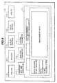
- Fig. 1 shows the entire configuration of the automatic analyzer.
- a multiplicity of reaction containers 12 made of light transmission material are mounted along the circular periphery of a reaction disk 10 which is provided so as to be rotatable intermittently.
- the reaction containers 12 are maintained at a predetermined temperature (for example, 37 C) by means of a thermostat bath 14.
- the temperature of the fluid within the thermostat bath 14 is adjusted by a constant temperature maintenance device 16.
- a multiplicity of sample cups 22 containing biological sample solution such as the blood or urine are placed on a sample disk 20.
- a pipette nozzle 26 attached to a movable arm 24 sucks a predetermined amount of sample from the sample cup 22 positioned at the suction position of the sample disk 20 and pipettes or discharges the sample thus sucked within the reaction container 12 positioned at the pipette position on the reaction disk 10.
- Each of these reagent bottles contains reagent solution corresponding to the analysis item to be analyzed by the automatic analyzer.
- Each of bar code readers annexed to the reagent cold reserving boxes 30A, 30B reads bar codes indicated at the outer walls of the reagent bottles at the time of registration of the reagents.
- the reagent identification information thus read is stored in a memory 56 described later together with the positional information of the reagent bottles on the reagent disk.
- the reagent pipette nozzles of the reagent pipetting mechanisms 36A, 36B suck reagent solution from the reagent bottles within the reagent cold reserving boxes 30A, 30B corresponding to the inspection items and pipette the reagent solution within the corresponding reaction containers 12 which are positioned at the reagent receiving positions on the reaction disk 10, respectively.
- the mixtures of the samples and the reagent solution within the reaction containers 12 are stirred by stirring mechanisms 38A, 38B, respectively.
- a sequence of the reaction containers 12 are rotated so as to pass a light measurement position sandwiched between a white light source 40 and a multi-wavelength photometer 42.
- the light passed through the reaction solution of the sample and the reagent solution within each of the reaction containers 12 is measured during the rotation of the reaction disk 10.
- An analog signal thus obtained through the light measurement at every sample is inputted into an analog-to-digital (A/D) converter 44.
- a reaction container washing mechanism 18 disposed in the vicinity of the reaction disk 10 washes the insides of the reaction containers 12 having been subjected to the light measurement thereby to make it possible to use the reaction containers repeatedly.
- a computer 50 is connected to a sample pipetting control section 28, a reagent pipetting control section 39 and the A/D converter 44 through an interface 52.
- the computer 50 sends a command to the sample pipetting control section 28 thereby to control the pipetting operation of the sample. Further, the computer 50 sends a command to the reagent pipetting control section 39 thereby to control the pipetting operation of the reagent.
- the light measurement value is converted into a digital value by the A/D converter 44 and then taken into the computer 50.
- the interface 52 is connected to a printer 54 for printing, the memory 56 serving as a storage device, a floppy disc drive device 58, a key board 60 for inputting an operation command or the like, and a CRT display 100 serving as a display device for displaying the screens.
- a screen display device a liquid crystal display or the like may be employed in place of the CRT display.
- the memory 56 is formed by a hard disc memory or an external memory, for example.
- the memory 56 stores information such as passwords of the respective operators, levels of the respective screens, analysis parameters, contents of the request for the analysis items, calibration results, analysis results, or the like.
- the analyzing operation of the sample in the automatic analyzer of Fig. 1 will be explained.
- the analysis parameters relating to the items capable of being analyzed by the automatic analyzer are inputted through an information input device such as the key board 60 and stored in the memory 56.
- An operator selects the inspection item requested at every sample by using the operation function screen described later.
- the information such as a patient ID is also inputted from the key board 60.
- the pipette nozzle 26 sucks a predetermined amount of the sample from the sample cup 22 and pipettes the sample thus sucked within the reaction container 12 in accordance with the analysis parameter.
- the reaction container 12 thus received the sample therein is transferred in accordance with the rotation of the reaction disk 10 and stopped at the reagent receiving position.
- the reagent pipette nozzles of the reagent pipetting mechanisms 36A, 36B suck predetermined amounts of reagent solution from the reagent bottles in accordance with the analysis parameter(s) of the inspection item(s) and pipette the reagent solution within the corresponding container(s) 12.
- the pipetting order between the sample and the reagent may not be limited to the aforesaid order and the reagent may be pipetted prior to the pipetting of the sample.
- the mixtures of the samples and the reagent solution within the reaction containers 12 are stirred by the stirring mechanisms 38A, 38B, respectively.
- the absorbance of the reaction solution within the reaction container 12 is measured by the multi-wavelength photometer 42.
- the absorbance thus measured is taken into the computer 50 through the A/D converter 44 and the interface 52.
- the absorbance is converted into component concentration data on the basis of the calibration curve which has been measured in advance by using the analysis method designated at every inspection item.
- the component concentration data representing the analysis results of the respective inspection items is outputted to the printer 54 and/or displayed on the CRT display 100.
- an operator Prior to the execution of the aforesaid measuring operation, an operator sets various kinds of parameters and registers the sample necessary for the analysis measurement. Further, the operator confirms the analysis result after the measurement by the operation screen displayed on the CRT display 100.
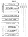
- Fig. 2 shows the relation between the kinds of the operation screens capable of being displayed on the CRT display 100 and the levels being allowed to an operator.
- the operation functions relating to the automatic analyzer are divided into a plurality of groups as shown by A to E in Fig. 2.
- the information of these operation function screens are stored in the memory 56.
- the operation function screens are selectively displayed under the control of the computer 50.
- the screens corresponding to the entire operation functions of the automatic analyzer are classified into the five groups, that is, a routine screen A, a reagent management screen B, an quality control screen C, a calibration screen D and a utility screen E.
- the operation function(s) of each of these groups accepts an instruction through at least one operation function screen and the operation function thus instructed is executed under the control of the computer 50.
- the routine screen A in Fig. 2 is formed by a patient sample request screen A1, a patient sample measuring result screen A2 and an initial setting screen A3.
- the utility screen E is formed by a maintenance and inspection screen E1, an analysis parameter setting screen E2 and a system parameter setting screen E3.
- the patient sample request screen A1 within the routine screen A is a screen for selecting an inspection item at every sample of each patient and registering the selected inspection item.
- the patient sample measuring result screen A2 is a screen for displaying the measured data of each patient so that an operator can confirm the measured data.
- the initial setting screen A3 is a screen for setting the condition and instructing the preparation operation for the automatic analyzer at the time of starting the analysis.
- the reagent management screen B is a screen for confirming the remaining amounts of the reagents within the respective reagent bottles and registering new reagents.
- the quality control screen C is a screen for setting the condition for monitoring the abnormality of the measured data or the degradation states of the reagents and for displaying the monitored result.
- the calibration screen D is a setting screen for executing the calibration by reacting the reagent with the standard reagent or calibrator.
- the maintenance and inspection screen E1 of the utility screen E is used at the time of setting the condition for executing the maintenance of the analyzer and used at the time of displaying the stored date representing the result of the periodical maintenance operation.
- the analysis parameter setting screen E2 is a screen for setting the parameter as the analysis condition to be stored as to the respective items capable of being analyzed.
- the system parameter setting screen E3 is a screen for setting the kinds of samples, the connection information of the system interface, the passwords of each operator, or the like.
- the operators of the automatic analyzer are persons of various levels from a beginner such as a doctor or a nurse who is not familiar with the operation of the automatic analyzer to a person in charge of the management of an analyzing room who is familiar with the operation of the automatic analyzer, or the like. Accordingly, in this embodiment, the operation functions accessible for these operators are divided into four levels from a level 1 to a level 4. Of these levels, the level 1 includes only the operation function which is required when a beginner such as a doctor or a nurse who usually does not operate the automatic analyzer uses the automatic analyzer, at the time of requiring an urgent inspection in the nighttime.
- the level 2 includes the operation function which is required in a hospital in the daytime or the like when an inspector operates the automatic analyzer and when a person in charge of the management of the analyzing room uses the automatic analyzer in order to check data.
- the level 3 includes, in addition to the operation functions of the levels 1 and 2, the operation function which is required when a skilled inspector changes the analysis parameter relating to the reagent etc.
- the level 4 includes, in addition to the operation functions of the levels 1 to 3, the operation function which is required when a service engineer or a person in charge of the management of the analyzing room uses the automatic analyzer. In other words, an operator of the level 4 can access all the operation functions of the automatic analyzer.
- the automatic analyzer uses the automatic analyzer at the time of urgent inspection, if an unnecessary screen is displayed, the urgent inspection of the sample can not be performed smoothly and further erroneous operation may be performed.
- a person in charge of the management of the analyzing room is required to set the system parameter or the like.
- the screens accessible for persons of the respective levels except for the level 4 are restricted as follows.
- the controller of the automatic analyzer displays only the operation function screens of the routine screen A, that is, the patient sample request screen A1, the patient sample measuring result screen A2 and the initial setting screen A3 on the CRT display 100 serving as the display device.
- the operator is able to set the minimum input necessary for the analysis of a sample by using these operation function screens.
- a doctor or a nurse can request the automatic analyzer to perform the urgent inspection of the sample and obtain the measured result of the sample by means of the operation function of the level 1.
- the controller inhibits the usage of the operation functions of the levels 2 to 4.
- the controller of the automatic analyzer allows to display, in addition to the respective screens A1, A2 and A3 of the routine screen A, the reagent management screen B, the quality control screen C, the calibration screen D and the maintenance and inspection screen E1 of the utility screen E on the CRT display 100 so that the operator can access to these operation function screens.
- the operator of the level 2 is not allowed to use all operation functions of the maintenance and inspection screen E1 but is restricted to use a part thereof.
- the controller of the automatic analyzer allows to display, in addition to all the operation function screens of the routine screen A, the reagent management screen B, the quality control screen C and the calibration screen D, the maintenance and inspection screen E1 and the analysis parameter setting screen E2 of the utility screen E on the CRT display 100 so that the operator can access to these operation function screens.
- the operator of the level 3 is allowed to access to all the operation function screens of Fig. 2 except for the system parameter setting screen E3.
- the controller of the automatic analyzer allows to display, in addition to all the operation screens allowed to the operator of the level 3, the system parameter setting screen E3 of the utility screen E on the CRT display 100 so that the operator can access to all the operation function screens of Fig. 2.
- the controller of the automatic analyzer allows a person in charge of the management of the analyzing room to access to the system parameter setting screen E3, other persons are selectively allowed to access to the operation function screens of the levels 1 to 3 but can not change the system parameter.
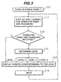
- step 300 when the power supply of the automatic analyzer is turned on, the screen display processing is started.
- step 310 the computer 50 serving as the controller shown in Fig. 1 displays an input screen for an operator name and a password on the CRT display 100.
- the operator name and the password are registered in the memory 56 in advance by using the system parameter setting screen E3.
- step 320 the computer 50 determines whether the operator name and the password have been inputted or not. If it is determined that the operator name and the password have been inputted, the process proceeds to step 330, while if it is determined that the operator name and the password have not been inputted, the process proceeds to step 340.
- the operator name and the password are not inputted in the case where the urgent inspection of a sample is required, for example.
- the automatic analyzer is controlled so as to perform the minimum operation function (that is, the urgent inspection request of a sample and the display of the measured result thereof) due to the emergency of the inspection even if the operator name and the password are not inputted.
- Such an operation function corresponds to the level 1 of Fig. 2.
- the determination that the operator name and the password have not been inputted is made on the basis of the state where the password etc. were not inputted within a predetermined period or the state where an instruction button for accessing to the level 1 was pushed without inputting the password.
- the controller displays the operation function selection screen described later with reference to Fig. 4 on the CRT display so that an operator can access only to an operation function selection button 110 for instructing the display of the operation function screen corresponding to the level 1. Accordingly, the analysis operation necessary for the urgent inspection of a sample can be executed by the automatic analyzer.
- the computer confirms the coincidence between the operator name and the password thus inputted and those registered in the memory 56 and then determines the level to be allowed for the operator, in step 330.
- step 340 the controller allows the operator to access to the operation function of the particular group in accordance with the level thus determined. That is, the computer 50 displays the operation function selection screen on the CRT display and controls the permission of the access to the selection buttons provided in corresponding to the respective operation function groups A to E, respectively, thereby to control the screen display so that the operator can open the operation function screen(s) corresponding to the level of the operator.
- the concrete contents of the screen display will be described later with reference to Figs. 4 to 6.
- step 350 the computer 50 accepts the input from the display screen or the key board 60 and executes the processing corresponding to the input. Thereafter, the process returns to step 310, whereat the computer 50 displays the input screen for a password etc. on the CRT display and waits for the next input.
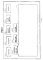
- a plurality of operation function selection buttons 110, 120, 130, 140 and 150 are displayed within the screen in Fig. 4 on the CRT display 100 but the individual operation function screens A1, A2 and A3 are not displayed yet.
- These operation function selection buttons are displayed in both cases where the operator inputted a password and where the operator did not input a password.
- the selection buttons accessible by the operator differ depending on the level of the operator. That is, when an operator is allowed to access only to the operation function of the level 1, since the operator is not allowed to access to the operation function groups B to E, the controller controls so that the operator can not access to the selection buttons 120, 130, 140, 150 corresponding to these groups.
- an area for displaying the selection buttons corresponding to the plurality of the operation function groups is formed at the upper side, and an area for displaying the operation function screen corresponding to the selection button selected thereafter is formed at the lower side.
- the operation function selection button 110 is used for instructing to display the routine screen A.
- the operation function selection button 110 is selected by using the key board 60, a mouse or the like, the patient sample request screen A1, the patient sample measuring result screen A2 and the initial setting screen A3 which are subclass operation function screens of the routine screen A can be displayed.
- the subclass operation function screens relating to the routine screen A are displayed in a hierarchy fashion or a multi-layer fashion.
- On the uppermost layer there appears the patient sample request screen A1 which is most high in necessity for an operator and has a tag 112.
- the patient sample measuring result screen A2 which is secondarily high in necessity for an operator appears in a manner that this screen is hidden and only a tag 114 appears.
- the initial setting screen A3 appear in a manner that this screen is hidden and only a tag 116 appears.
- subclass operation function screens are configured and selected in a form fashion.
- the subclass operation function screen corresponding to the selected tag appears on the uppermost layer.
- the patient sample request screen A1 is displayed.
- a column 112A for inputting the number of a sample (sample No.) and a plurality of inspection item selection buttons 112B are displayed.
- the list of these inspection items may be configured as a plural sheets of form.
- the operator can easily operate the request for the inspection of a sample by merely inputting the sample No. into the column 112A and selecting the inspection item from the series of selection buttons 112B at every sample.
- the button 120 is used for selecting the operation function group of the reagent management screen B
- the button 130 is used for selecting the operation function group of the quality control screen C
- the button 140 is used for selecting the operation function group of the calibration screen D
- the button 150 is used for selecting the operation function group of the utility screen E.
- an operator is allowed to access only to the operation function of the level 1, the operator is restricted not to access to the selection buttons 120, 130, 140, 150 other than the selection button 110.
- the operation function selection buttons corresponding to the groups which are allowed to be accessed in accordance with the level are displayed in different color from the operation function selection buttons corresponding to the groups which are not allowed to be accessed in accordance with the level.
- the screen to be accessible and the screen not to be accessible are displayed in a different way visually in a manner that the non-accessible buttons 120 to 150 shown by dotted lines are displayed by gray and the accessible button 110 is displayed in a highlight manner, for example. For instance, even when an operator allowed to access only to the operation function of the level 1 tries to select the button 120, the reagent management screen B corresponding to the button 120 is not displayed.
- the controller allows an operator to access to the reagent management screen B, the quality control screen C and the calibration screen D in addition to the subclass operation function screens A1, A2 and A3 of the routine screen A. Further, the operator is allowed to partially access to the maintenance and inspection screen E1 which is the subclass operation function screen of the utility screen E. However, the operator is not allowed to access to both the analysis parameter setting screen E2 and the system parameter setting screen E3. Accordingly, in step 340 of Fig. 3, the plurality of operation function selection buttons 110, 120, 130, 140 and 150shown at the upper area of the display screen of the CRT display 100 are displayed in a highlight manner representing to be accessible as shown by steady lines in Fig. 5.
- step 350 of Fig. 3 when the operation function selection button 150 corresponding to the operation function group of the utility screen E is selected, the plurality of the subclass operation function screens E1, E2, E3 relating to this selection button 150 are displayed in a hierarchy fashion or a multi-layer fashion.
- the level of the operator is the level 2
- the operator is allowed to access only to the maintenance and inspection screen E1 of the utility screen E.
- both the analysis parameter setting screen E2 and the system parameter setting screen E3 are hidden by the maintenance and inspection screen E1 except for tags 154 and 156 of these screens E2 and E3.
- the tag 152 of the maintenance and inspection screen E1 accessible by an operator is displayed in a highlight manner as shown by the steady line in Fig. 5, but the tag 154 of the analysis parameter setting screen E2 and the tag 156 of the system parameter setting screen E3 each not allowed to access are displayed by gray as shown by dotted lines in Fig. 5.
- the utility screen E includes the plurality of the subclass operation function screens E1, E2, E3 which are arranged in a manner that the order of the multi-layers thereof is the order of the higher level of the subclass operation functions.
- an operator who is allowed to access to the operation function of the level 2 can access to the maintenance and inspection screen E1 of the uppermost layer.
- An operator who is allowed to access to the operation function of the level 3 can access to the analysis parameter setting screen E2 of the secondary layer, and an operator who is allowed to access to the operation function of the level 4 can access to the system parameter setting screen E3 of the lowermost layer.
- An operator who is allowed to access to the operation function of the upper level 3 or 4 can open the corresponding lower operation function screen E2 or E3 on the uppermost layer by selecting the tag 154 or 156. In this manner, since an operator determined to be the level 2 can not access to both the analysis parameter setting screen E2 and the system parameter setting screen E3, the operator is prevented from erroneously changing the setting on the basis of these screens.
- the erasure of the management data and the accumulation of the management data can not be accessed by an operator of the level 2 but are allowed to be accessed by an operator of the levels 3 and 4, whereby the management data is prevented from being erroneously erased by an operator of the level 2.
- An operator who is allowed to access to the operation function of the level 3 can also manage the reagent, the calibration or the like.
- the setting operation of the analysis parameter or the like requires the special knowledge such as the designation of an amount of reagent, wavelength, light measurement point, designation of an alarm level, determination of the calibration result or the like, However, since such a setting operation can be performed only by the specialist, it can be prevented that the reliability of the measured data is degraded due to the access of an operator not having such a special knowledge.
- a person in charge of the management of the analyzing room can set the level to be accessible by an operator by using the system parameter setting screen E3.
- Passwords allocated to the respective operators can be registered also by using the system parameter setting screen E3.
- the passwords are allocated only to persons of the levels 2 to 4 so as to prevent that other person illegally use the automatic analyzer.
- the password can be changed also by using the system parameter setting screen E3.
- the automatic analyzer since the levels of operators are set and the screens accessible by the operators are restricted depending on the levels in advance, even a beginner etc. of the automatic analyzer can easily operate the automatic analyzer and further the erroneous operation can be prevented. Since the automatic analyzer is provided with a user interface having such a screen configuration that the operation functions accessible by respective operators among the entire operation functions are clearly indicated and the plurality of the subclass operation function screens belonging to the operation function group selected by an operator are displayed in a hierarchy fashion or a multi-layer fashion, so that the operability and the reliability of the automatic analyzer can be improved.
Landscapes
- Physics & Mathematics (AREA)
- Health & Medical Sciences (AREA)
- Life Sciences & Earth Sciences (AREA)
- Chemical & Material Sciences (AREA)
- Analytical Chemistry (AREA)
- Biochemistry (AREA)
- General Health & Medical Sciences (AREA)
- General Physics & Mathematics (AREA)
- Immunology (AREA)
- Pathology (AREA)
- Automatic Analysis And Handling Materials Therefor (AREA)
Claims (4)
- Ein automatischer Analysierer zum automatischen Analysieren einer Probe und zum Erhalt einer Konzentration eines Untersuchungsgegenstandes der Probe, mit:dadurch gekennzeichnet, dasseinem Speicher (56), der Informationen von Betriebsfunktionen speichert, welche dem automatischen Analysierer zugehörig sind, wobei die Betriebsfunktionen in eine Mehrzahl von Gruppen unterteilt sind;einer Steuerung (50), die so ausgelegt ist, dass sie einen Zugriffs-Berechtigungsgrad entsprechend einem Password, welches eingegenen wurde, bestimmt, und einen Zugriff auf Betriebsfunktionen einer oder mehrerer der Mehrzahl von Gruppen abhängig von dem bestimmten Zugriffs-Berechtigungsgrad erlaubt; undeiner Anzeigevorrichtung (100) zur Anzeige einer Bildschirmdarstellung mit einem Bereich zur Anzeige von Betriebsfunktions-Wahlschaltern (110, 120, 130, 140, 150) entsprechend der jeweiligen Gruppen der Betriebsfunktionen und einem Bereich zur Anzeige einer Betriebsfunktions-Bildschirmdarstellung (A, B, C, D, E) entsprechend einem Ausgewählten aus den Betriebsfunktions-Wahlschaltern, wobei:die Steuerung (50) dafür ausgelegt ist, Betriebsfunktions-Wahlschalter als darauf zugreifbar zu steuern, wenn Zugriff auf ihre jeweiligen Gruppen von Betriebsfunktionen basierend auf dem bestimmten Zugriffs-Berechtigungsgrad erlaubt wurde, und jegliche verbleibenden Betriebsfunktions-Wahlschalter als nicht darauf zugreifbar zu steuern, wenn Zugriff auf ihre jeweiligen Gruppen nicht erlaubt wurde,
die Steuerung (50) dafür ausgelegt ist, dass sie den Zugriffs-Berechtigungsgrad als einen bestimmt, in dem Zugriff zu einem der Betriebsfunktions-Wahlschalter entsprechend einer Betriebsfunktion erlaubt ist, die für eine dringende Analyse einer Probe notwendig ist, wenn das Password nach Einschalten einer Energieversorgung des automatischen Analysierers nicht eingegeben wurde. - Der automatische Analysierer nach Anspruch 1, wobei Betriebsfunktions-Wahlschalter, auf die Zugriff erlaubt ist, in unterschiedlicehn Farben zu Betriebsfunktions-Wahlschaltern dargestellt werden, für die kein Zugriff erlaubt ist.
- Der automatische Analysierer nach Anspruch 1, wobei in einem Fall, in welchem eine Mehrzahl von Betriebsfunktions-Bildschirmdarstellungen einem ausgewählten Betriebsfunktions-Wahlschalter zugeordnet ist, für welchen Zugriff erlaubt wurde, die Mehrzahl von Betriebsfunktions-Bildschirmdarstellungen in mehrlagiger Weise dargestellt wird.
- Der automatische Analysierer nach Anspruch 3, wobei eine aus der Mehrzahl von Betriebsfunktions-Bildschirmdarstellungen entsprechend einer Betriebsfunktion mit dem niedrigsten Wert in einer obersten Lage dargestellt wird.
Applications Claiming Priority (2)
| Application Number | Priority Date | Filing Date | Title |
|---|---|---|---|
| JP11043698 | 1998-04-21 | ||
| JP11043698 | 1998-04-21 |
Publications (2)
| Publication Number | Publication Date |
|---|---|
| EP0952452A1 EP0952452A1 (de) | 1999-10-27 |
| EP0952452B1 true EP0952452B1 (de) | 2005-07-20 |
Family
ID=14535688
Family Applications (1)
| Application Number | Title | Priority Date | Filing Date |
|---|---|---|---|
| EP99107304A Expired - Lifetime EP0952452B1 (de) | 1998-04-21 | 1999-04-19 | Automatische Analysevorrichtung mit einstellbarer Betriebsfunktionsbeschränkung |
Country Status (3)
| Country | Link |
|---|---|
| US (1) | US6544476B1 (de) |
| EP (1) | EP0952452B1 (de) |
| DE (1) | DE69926168T2 (de) |
Families Citing this family (29)
| Publication number | Priority date | Publication date | Assignee | Title |
|---|---|---|---|---|
| US7249372B1 (en) * | 2000-01-14 | 2007-07-24 | Target Training International Performance Systems | Network based document distribution method |
| JP3603019B2 (ja) * | 2000-12-15 | 2004-12-15 | 株式会社日立製作所 | 生化学自動分析装置 |
| US20020168292A1 (en) * | 2001-05-14 | 2002-11-14 | Whisenhunt Donald Wayne | Systems and methods for the high throughput preparation and analysis of chemical reactions |
| JP4184721B2 (ja) * | 2002-06-21 | 2008-11-19 | シスメックス株式会社 | ユーザインターフェイスおよびそれを備えた分析装置 |
| JP3990944B2 (ja) * | 2002-06-28 | 2007-10-17 | 株式会社日立ハイテクノロジーズ | 自動分析装置 |
| US7185288B2 (en) * | 2003-07-18 | 2007-02-27 | Dade Behring Inc. | Operator interface module segmented by function in an automatic clinical analyzer |
| JP4733949B2 (ja) * | 2004-09-17 | 2011-07-27 | シスメックス株式会社 | 分析装置、プログラムおよびそのプログラムを記録した記録媒体 |
| JP2006308366A (ja) * | 2005-04-27 | 2006-11-09 | Hitachi High-Technologies Corp | 化学分析装置及び化学分析カートリッジ |
| JP4755874B2 (ja) * | 2005-09-27 | 2011-08-24 | シスメックス株式会社 | 検体分析装置、検体分析用処理コンピュータ、検体分析装置における操作用画面の表示方法、及び検体分析装置用処理コンピュータのためのコンピュータプログラム |
| ES2629330T3 (es) | 2006-08-22 | 2017-08-08 | Sysmex Corporation | Analizador de muestras |
| JP2008209326A (ja) * | 2007-02-28 | 2008-09-11 | Hitachi High-Technologies Corp | 自動分析装置 |
| EP1986013A3 (de) | 2007-04-27 | 2013-04-03 | Sysmex Corporation | Probenanalysegerät |
| JP3133890U (ja) * | 2007-05-16 | 2007-07-26 | 株式会社日立ハイテクノロジーズ | 検体処理システム |
| JP5123111B2 (ja) | 2008-09-03 | 2013-01-16 | 株式会社東芝 | 自動分析装置 |
| JP5346737B2 (ja) * | 2009-08-12 | 2013-11-20 | シスメックス株式会社 | 検体検査装置およびそれに用いる情報管理装置 |
| JP5855372B2 (ja) * | 2011-07-07 | 2016-02-09 | シスメックス株式会社 | 検体分析装置及びコンピュータプログラム |
| EP3553690B8 (de) * | 2012-03-02 | 2021-12-08 | F. Hoffmann-La Roche AG | Bestimmung einer endgeräteposition zur anzeige eines gui-elements |
| DE102012102918A1 (de) * | 2012-04-03 | 2013-10-10 | Eppendorf Ag | Laborgerätesystem und Laborgerät zum Behandeln von Fluiden und Feststoffen sowie Verfahren zum Betreiben eines Laborgerätes |
| US11354560B2 (en) | 2013-01-18 | 2022-06-07 | Amatech Group Limited | Smartcards with multiple coupling frames |
| EP2857842B1 (de) | 2013-10-07 | 2022-09-21 | Eppendorf SE | Zugriffssteuerung für ein Laborgerät, Laborgerät mit Zugriffssteuerung und Verfahren zur gerätegesteuerten Behandlung von Laborproben |
| ES2877222T3 (es) | 2013-10-07 | 2021-11-16 | Eppendorf Ag | Instrumento de laboratorio para el procesamiento controlado por instrumento de al menos una muestra de laboratorio, y un método para configurar el instrumento de laboratorio mediante el sistema de control de configuración |
| EP2857844B1 (de) | 2013-10-07 | 2021-12-01 | Eppendorf AG | Laborgerät, System und Verfahren zur gerätegesteuerten Behandlung mindestens einer Laborprobe unter Verwendung mindestens eines Verbrauchsartikels |
| EP2857843A1 (de) | 2013-10-07 | 2015-04-08 | Eppendorf Ag | System aufweisend mindestens zwei Laborgeräte zur gerätegesteuerten Bearbeitung einer Teilaufgabe bei einem Behandlungsprozess beinhaltend Behandlungen mindestens einer Laborprobe, Laborgerät und Verfahren |
| JP5820498B2 (ja) * | 2014-04-03 | 2015-11-24 | シスメックス株式会社 | 検体検査装置 |
| EP3153864B1 (de) | 2015-10-06 | 2019-11-20 | Roche Diagniostics GmbH | Vorrichtung und verfahren zum verarbeiten von mindestens einer probe |
| EP3660513A4 (de) * | 2017-07-25 | 2021-04-28 | Hitachi High-Tech Corporation | Automatische analysevorrichtung |
| CN108693363B (zh) * | 2018-04-17 | 2020-10-27 | 杭州电子科技大学 | 一种未知血型的交叉配血试验仪 |
| CN108982881B (zh) * | 2018-04-17 | 2021-03-23 | 杭州电子科技大学 | 适用于已知血型的自动交叉配血试验方法 |
| CN108693362B (zh) * | 2018-04-17 | 2020-10-27 | 杭州电子科技大学 | 一种适用于已知血型的交叉配血方法 |
Family Cites Families (13)
| Publication number | Priority date | Publication date | Assignee | Title |
|---|---|---|---|---|
| US3693166A (en) * | 1970-09-21 | 1972-09-19 | Searle Medidata Inc | Data interpretation terminal |
| US4873633A (en) * | 1985-10-18 | 1989-10-10 | Cetus Corporation | User controlled off-center light absorbance reading adjuster in a liquid handling and reaction system |
| US4857716A (en) * | 1986-05-12 | 1989-08-15 | Clinicom Incorporated | Patient identification and verification system and method |
| US5029065A (en) | 1986-12-16 | 1991-07-02 | Ciba-Geigy Corporation | Control system for a sample preparation system |
| JPH01250758A (ja) * | 1988-03-31 | 1989-10-05 | Toshiba Corp | 自動化学分析装置 |
| US5068798A (en) | 1989-03-03 | 1991-11-26 | Precision Systems, Inc. | Process environment monitoring system |
| CA2155932A1 (en) * | 1993-12-14 | 1995-06-22 | Tadakazu Yamauchi | Medical measuring apparatus |
| JP3048029B2 (ja) * | 1994-03-16 | 2000-06-05 | 株式会社日立製作所 | 液体クロマトグラフ分析システム |
| JP3063564B2 (ja) | 1995-03-17 | 2000-07-12 | 株式会社日立製作所 | 自動分析装置 |
| JPH09211003A (ja) | 1996-02-01 | 1997-08-15 | Hitachi Ltd | 自動分析装置 |
| JP3597958B2 (ja) * | 1996-11-15 | 2004-12-08 | 株式会社日立製作所 | 自動分析装置 |
| EP0871034B1 (de) | 1997-04-10 | 2007-03-07 | Hitachi, Ltd. | Automatische Analysevorrichtung |
| JP3424547B2 (ja) * | 1998-02-26 | 2003-07-07 | 株式会社日立製作所 | 液体クロマトグラフ |
-
1999
- 1999-04-19 DE DE69926168T patent/DE69926168T2/de not_active Expired - Lifetime
- 1999-04-19 EP EP99107304A patent/EP0952452B1/de not_active Expired - Lifetime
- 1999-04-20 US US09/294,433 patent/US6544476B1/en not_active Expired - Lifetime
Also Published As
| Publication number | Publication date |
|---|---|
| DE69926168T2 (de) | 2006-01-12 |
| EP0952452A1 (de) | 1999-10-27 |
| DE69926168D1 (de) | 2005-08-25 |
| US6544476B1 (en) | 2003-04-08 |
Similar Documents
| Publication | Publication Date | Title |
|---|---|---|
| EP0952452B1 (de) | Automatische Analysevorrichtung mit einstellbarer Betriebsfunktionsbeschränkung | |
| JP3849343B2 (ja) | 自動分析装置 | |
| JP3156550B2 (ja) | 試薬管理の方法および装置 | |
| EP1873530B1 (de) | Probenanalysegerät | |
| US8741229B2 (en) | Sample analyzer, reagent information displaying method and computer program product | |
| EP1873531B1 (de) | Probenanalysegerät | |
| EP0510686B1 (de) | Automatischer Analysenapparat, geeignet zum Lesen von Behälterdaten, und Verfahren zur Handhabung von darin verwendeten Reagenzien | |
| US7185288B2 (en) | Operator interface module segmented by function in an automatic clinical analyzer | |
| EP0973115A2 (de) | Benutzerschnittstelle für ein biomedizinisches Analysesystem | |
| US20110208536A1 (en) | Clinical test information managing apparatus and non-transitory storage medium | |
| US7716607B2 (en) | Automatic analyzer | |
| EP3745140A1 (de) | Automatisierter analysator und verfahren zur steuerung des automatisierten analysators | |
| JPWO2019021625A1 (ja) | 自動分析装置 | |
| JP6925194B2 (ja) | 自動分析装置 | |
| JPH0972909A (ja) | 自動分析装置 | |
| JP4434180B2 (ja) | 自動分析装置 | |
| JP3061963B2 (ja) | 自動分析装置 | |
| JPH0821839A (ja) | 自動分析装置の検体種識別方法 | |
| JP5351606B2 (ja) | 生化学自動分析装置 | |
| JPH06138131A (ja) | 自動分析装置 | |
| JP7669494B2 (ja) | 自動分析装置、データ処理装置、データ処理方法及びプログラム | |
| JP2018124223A (ja) | 自動分析装置及びプログラム |
Legal Events
| Date | Code | Title | Description |
|---|---|---|---|
| PUAI | Public reference made under article 153(3) epc to a published international application that has entered the european phase |
Free format text: ORIGINAL CODE: 0009012 |
|
| 17P | Request for examination filed |
Effective date: 19990419 |
|
| AK | Designated contracting states |
Kind code of ref document: A1 Designated state(s): DE FR GB |
|
| AX | Request for extension of the european patent |
Free format text: AL;LT;LV;MK;RO;SI |
|
| AKX | Designation fees paid |
Free format text: DE FR GB |
|
| 17Q | First examination report despatched |
Effective date: 20040628 |
|
| TPAC | Observations filed by third parties |
Free format text: ORIGINAL CODE: EPIDOSNTIPA |
|
| GRAP | Despatch of communication of intention to grant a patent |
Free format text: ORIGINAL CODE: EPIDOSNIGR1 |
|
| GRAS | Grant fee paid |
Free format text: ORIGINAL CODE: EPIDOSNIGR3 |
|
| GRAA | (expected) grant |
Free format text: ORIGINAL CODE: 0009210 |
|
| RAP1 | Party data changed (applicant data changed or rights of an application transferred) |
Owner name: HITACHI, LTD. |
|
| AK | Designated contracting states |
Kind code of ref document: B1 Designated state(s): DE FR GB |
|
| REG | Reference to a national code |
Ref country code: GB Ref legal event code: FG4D |
|
| REF | Corresponds to: |
Ref document number: 69926168 Country of ref document: DE Date of ref document: 20050825 Kind code of ref document: P |
|
| PG25 | Lapsed in a contracting state [announced via postgrant information from national office to epo] |
Ref country code: GB Free format text: LAPSE BECAUSE OF NON-PAYMENT OF DUE FEES Effective date: 20060419 |
|
| ET | Fr: translation filed | ||
| PLBE | No opposition filed within time limit |
Free format text: ORIGINAL CODE: 0009261 |
|
| STAA | Information on the status of an ep patent application or granted ep patent |
Free format text: STATUS: NO OPPOSITION FILED WITHIN TIME LIMIT |
|
| 26N | No opposition filed |
Effective date: 20060421 |
|
| GBPC | Gb: european patent ceased through non-payment of renewal fee |
Effective date: 20060419 |
|
| REG | Reference to a national code |
Ref country code: FR Ref legal event code: PLFP Year of fee payment: 18 |
|
| REG | Reference to a national code |
Ref country code: FR Ref legal event code: PLFP Year of fee payment: 19 |
|
| REG | Reference to a national code |
Ref country code: FR Ref legal event code: PLFP Year of fee payment: 20 |
|
| PGFP | Annual fee paid to national office [announced via postgrant information from national office to epo] |
Ref country code: FR Payment date: 20180315 Year of fee payment: 20 |
|
| PGFP | Annual fee paid to national office [announced via postgrant information from national office to epo] |
Ref country code: DE Payment date: 20180404 Year of fee payment: 20 |
|
| REG | Reference to a national code |
Ref country code: DE Ref legal event code: R071 Ref document number: 69926168 Country of ref document: DE |