EP0952621B1 - Alkalische speicherbatterie und verfahren zum laden dieser batterie - Google Patents
Alkalische speicherbatterie und verfahren zum laden dieser batterie Download PDFInfo
- Publication number
- EP0952621B1 EP0952621B1 EP97949220A EP97949220A EP0952621B1 EP 0952621 B1 EP0952621 B1 EP 0952621B1 EP 97949220 A EP97949220 A EP 97949220A EP 97949220 A EP97949220 A EP 97949220A EP 0952621 B1 EP0952621 B1 EP 0952621B1
- Authority
- EP
- European Patent Office
- Prior art keywords
- charging
- positive electrode
- storage battery
- potential
- alkali storage
- Prior art date
- Legal status (The legal status is an assumption and is not a legal conclusion. Google has not performed a legal analysis and makes no representation as to the accuracy of the status listed.)
- Expired - Lifetime
Links
- 238000000034 method Methods 0.000 title claims description 18
- 239000003513 alkali Substances 0.000 claims description 77
- MYMOFIZGZYHOMD-UHFFFAOYSA-N Dioxygen Chemical compound O=O MYMOFIZGZYHOMD-UHFFFAOYSA-N 0.000 claims description 54
- 229910001882 dioxygen Inorganic materials 0.000 claims description 54
- 239000006182 cathode active material Substances 0.000 claims description 44
- 239000011572 manganese Substances 0.000 claims description 33
- PWHULOQIROXLJO-UHFFFAOYSA-N Manganese Chemical compound [Mn] PWHULOQIROXLJO-UHFFFAOYSA-N 0.000 claims description 30
- 229910052748 manganese Inorganic materials 0.000 claims description 30
- 239000003792 electrolyte Substances 0.000 claims description 14
- 239000006183 anode active material Substances 0.000 claims description 5
- HCHKCACWOHOZIP-UHFFFAOYSA-N Zinc Chemical compound [Zn] HCHKCACWOHOZIP-UHFFFAOYSA-N 0.000 claims description 4
- 229910052725 zinc Inorganic materials 0.000 claims description 4
- 239000011701 zinc Substances 0.000 claims description 4
- 230000000052 comparative effect Effects 0.000 description 40
- 239000003795 chemical substances by application Substances 0.000 description 22
- 238000007599 discharging Methods 0.000 description 22
- BFDHFSHZJLFAMC-UHFFFAOYSA-L nickel(ii) hydroxide Chemical compound [OH-].[OH-].[Ni+2] BFDHFSHZJLFAMC-UHFFFAOYSA-L 0.000 description 16
- 230000003247 decreasing effect Effects 0.000 description 14
- 229940099596 manganese sulfate Drugs 0.000 description 11
- 239000011702 manganese sulphate Substances 0.000 description 11
- 235000007079 manganese sulphate Nutrition 0.000 description 11
- SQQMAOCOWKFBNP-UHFFFAOYSA-L manganese(II) sulfate Chemical compound [Mn+2].[O-]S([O-])(=O)=O SQQMAOCOWKFBNP-UHFFFAOYSA-L 0.000 description 11
- LGQLOGILCSXPEA-UHFFFAOYSA-L nickel sulfate Chemical compound [Ni+2].[O-]S([O-])(=O)=O LGQLOGILCSXPEA-UHFFFAOYSA-L 0.000 description 11
- 229910000363 nickel(II) sulfate Inorganic materials 0.000 description 11
- 239000000243 solution Substances 0.000 description 10
- 230000014759 maintenance of location Effects 0.000 description 7
- 229910052759 nickel Inorganic materials 0.000 description 5
- CSNNHWWHGAXBCP-UHFFFAOYSA-L Magnesium sulfate Chemical compound [Mg+2].[O-][S+2]([O-])([O-])[O-] CSNNHWWHGAXBCP-UHFFFAOYSA-L 0.000 description 4
- PXHVJJICTQNCMI-UHFFFAOYSA-N Nickel Chemical compound [Ni] PXHVJJICTQNCMI-UHFFFAOYSA-N 0.000 description 4
- QVGXLLKOCUKJST-UHFFFAOYSA-N atomic oxygen Chemical compound [O] QVGXLLKOCUKJST-UHFFFAOYSA-N 0.000 description 4
- OSGAYBCDTDRGGQ-UHFFFAOYSA-L calcium sulfate Chemical compound [Ca+2].[O-]S([O-])(=O)=O OSGAYBCDTDRGGQ-UHFFFAOYSA-L 0.000 description 4
- 238000011161 development Methods 0.000 description 4
- 230000018109 developmental process Effects 0.000 description 4
- NUJOXMJBOLGQSY-UHFFFAOYSA-N manganese dioxide Chemical compound O=[Mn]=O NUJOXMJBOLGQSY-UHFFFAOYSA-N 0.000 description 4
- 239000001301 oxygen Substances 0.000 description 4
- 229910052760 oxygen Inorganic materials 0.000 description 4
- 239000011800 void material Substances 0.000 description 4
- KWYUFKZDYYNOTN-UHFFFAOYSA-M Potassium hydroxide Chemical compound [OH-].[K+] KWYUFKZDYYNOTN-UHFFFAOYSA-M 0.000 description 3
- HEMHJVSKTPXQMS-UHFFFAOYSA-M Sodium hydroxide Chemical compound [OH-].[Na+] HEMHJVSKTPXQMS-UHFFFAOYSA-M 0.000 description 3
- 239000011149 active material Substances 0.000 description 3
- 229910052793 cadmium Inorganic materials 0.000 description 3
- BDOSMKKIYDKNTQ-UHFFFAOYSA-N cadmium atom Chemical compound [Cd] BDOSMKKIYDKNTQ-UHFFFAOYSA-N 0.000 description 3
- OJIJEKBXJYRIBZ-UHFFFAOYSA-N cadmium nickel Chemical compound [Ni].[Cd] OJIJEKBXJYRIBZ-UHFFFAOYSA-N 0.000 description 3
- 238000006243 chemical reaction Methods 0.000 description 3
- 229910052987 metal hydride Inorganic materials 0.000 description 3
- 150000002815 nickel Chemical group 0.000 description 3
- QELJHCBNGDEXLD-UHFFFAOYSA-N nickel zinc Chemical compound [Ni].[Zn] QELJHCBNGDEXLD-UHFFFAOYSA-N 0.000 description 3
- 239000002245 particle Substances 0.000 description 3
- 229920001343 polytetrafluoroethylene Polymers 0.000 description 3
- 239000004810 polytetrafluoroethylene Substances 0.000 description 3
- 238000001556 precipitation Methods 0.000 description 3
- QGZKDVFQNNGYKY-UHFFFAOYSA-N Ammonia Chemical compound N QGZKDVFQNNGYKY-UHFFFAOYSA-N 0.000 description 2
- XEEYBQQBJWHFJM-UHFFFAOYSA-N Iron Chemical compound [Fe] XEEYBQQBJWHFJM-UHFFFAOYSA-N 0.000 description 2
- 238000002441 X-ray diffraction Methods 0.000 description 2
- XLOMVQKBTHCTTD-UHFFFAOYSA-N Zinc monoxide Chemical compound [Zn]=O XLOMVQKBTHCTTD-UHFFFAOYSA-N 0.000 description 2
- DIZPMCHEQGEION-UHFFFAOYSA-H aluminium sulfate (anhydrous) Chemical compound [Al+3].[Al+3].[O-]S([O-])(=O)=O.[O-]S([O-])(=O)=O.[O-]S([O-])(=O)=O DIZPMCHEQGEION-UHFFFAOYSA-H 0.000 description 2
- 239000011230 binding agent Substances 0.000 description 2
- QCUOBSQYDGUHHT-UHFFFAOYSA-L cadmium sulfate Chemical compound [Cd+2].[O-]S([O-])(=O)=O QCUOBSQYDGUHHT-UHFFFAOYSA-L 0.000 description 2
- 229910000331 cadmium sulfate Inorganic materials 0.000 description 2
- 229910017052 cobalt Inorganic materials 0.000 description 2
- 239000010941 cobalt Substances 0.000 description 2
- GUTLYIVDDKVIGB-UHFFFAOYSA-N cobalt atom Chemical compound [Co] GUTLYIVDDKVIGB-UHFFFAOYSA-N 0.000 description 2
- 229910000361 cobalt sulfate Inorganic materials 0.000 description 2
- 229940044175 cobalt sulfate Drugs 0.000 description 2
- KTVIXTQDYHMGHF-UHFFFAOYSA-L cobalt(2+) sulfate Chemical compound [Co+2].[O-]S([O-])(=O)=O KTVIXTQDYHMGHF-UHFFFAOYSA-L 0.000 description 2
- 239000004020 conductor Substances 0.000 description 2
- 229910052943 magnesium sulfate Inorganic materials 0.000 description 2
- 235000019341 magnesium sulphate Nutrition 0.000 description 2
- WPBNNNQJVZRUHP-UHFFFAOYSA-L manganese(2+);methyl n-[[2-(methoxycarbonylcarbamothioylamino)phenyl]carbamothioyl]carbamate;n-[2-(sulfidocarbothioylamino)ethyl]carbamodithioate Chemical compound [Mn+2].[S-]C(=S)NCCNC([S-])=S.COC(=O)NC(=S)NC1=CC=CC=C1NC(=S)NC(=O)OC WPBNNNQJVZRUHP-UHFFFAOYSA-L 0.000 description 2
- 239000000203 mixture Substances 0.000 description 2
- -1 polytetrafluoroethylene Polymers 0.000 description 2
- 230000000630 rising effect Effects 0.000 description 2
- 229910052720 vanadium Inorganic materials 0.000 description 2
- NWONKYPBYAMBJT-UHFFFAOYSA-L zinc sulfate Chemical compound [Zn+2].[O-]S([O-])(=O)=O NWONKYPBYAMBJT-UHFFFAOYSA-L 0.000 description 2
- 229910000368 zinc sulfate Inorganic materials 0.000 description 2
- 229960001763 zinc sulfate Drugs 0.000 description 2
- OYPRJOBELJOOCE-UHFFFAOYSA-N Calcium Chemical compound [Ca] OYPRJOBELJOOCE-UHFFFAOYSA-N 0.000 description 1
- OKTJSMMVPCPJKN-UHFFFAOYSA-N Carbon Chemical compound [C] OKTJSMMVPCPJKN-UHFFFAOYSA-N 0.000 description 1
- 229920000298 Cellophane Polymers 0.000 description 1
- 229910021503 Cobalt(II) hydroxide Inorganic materials 0.000 description 1
- FYYHWMGAXLPEAU-UHFFFAOYSA-N Magnesium Chemical compound [Mg] FYYHWMGAXLPEAU-UHFFFAOYSA-N 0.000 description 1
- 229910021529 ammonia Inorganic materials 0.000 description 1
- 229910052791 calcium Inorganic materials 0.000 description 1
- 239000011575 calcium Substances 0.000 description 1
- ASKVAEGIVYSGNY-UHFFFAOYSA-L cobalt(ii) hydroxide Chemical compound [OH-].[OH-].[Co+2] ASKVAEGIVYSGNY-UHFFFAOYSA-L 0.000 description 1
- 150000001875 compounds Chemical class 0.000 description 1
- 239000013078 crystal Substances 0.000 description 1
- 230000001419 dependent effect Effects 0.000 description 1
- 238000010586 diagram Methods 0.000 description 1
- 239000008151 electrolyte solution Substances 0.000 description 1
- 229910002804 graphite Inorganic materials 0.000 description 1
- 239000010439 graphite Substances 0.000 description 1
- IGUXCTSQIGAGSV-UHFFFAOYSA-K indium(iii) hydroxide Chemical compound [OH-].[OH-].[OH-].[In+3] IGUXCTSQIGAGSV-UHFFFAOYSA-K 0.000 description 1
- 229910052742 iron Inorganic materials 0.000 description 1
- 238000010030 laminating Methods 0.000 description 1
- 229910052749 magnesium Inorganic materials 0.000 description 1
- 239000011777 magnesium Substances 0.000 description 1
- 150000002697 manganese compounds Chemical class 0.000 description 1
- 239000011259 mixed solution Substances 0.000 description 1
- 239000004745 nonwoven fabric Substances 0.000 description 1
- 229920000098 polyolefin Polymers 0.000 description 1
- 239000002244 precipitate Substances 0.000 description 1
- 238000004321 preservation Methods 0.000 description 1
- 229910052709 silver Inorganic materials 0.000 description 1
- 239000004332 silver Substances 0.000 description 1
- 230000008961 swelling Effects 0.000 description 1
- XLYOFNOQVPJJNP-UHFFFAOYSA-N water Substances O XLYOFNOQVPJJNP-UHFFFAOYSA-N 0.000 description 1
- 238000004804 winding Methods 0.000 description 1
- 239000011787 zinc oxide Substances 0.000 description 1
Images

Classifications
-
- H—ELECTRICITY
- H01—ELECTRIC ELEMENTS
- H01M—PROCESSES OR MEANS, e.g. BATTERIES, FOR THE DIRECT CONVERSION OF CHEMICAL ENERGY INTO ELECTRICAL ENERGY
- H01M10/00—Secondary cells; Manufacture thereof
- H01M10/42—Methods or arrangements for servicing or maintenance of secondary cells or secondary half-cells
- H01M10/44—Methods for charging or discharging
-
- H—ELECTRICITY
- H01—ELECTRIC ELEMENTS
- H01M—PROCESSES OR MEANS, e.g. BATTERIES, FOR THE DIRECT CONVERSION OF CHEMICAL ENERGY INTO ELECTRICAL ENERGY
- H01M10/00—Secondary cells; Manufacture thereof
- H01M10/24—Alkaline accumulators
-
- H—ELECTRICITY
- H01—ELECTRIC ELEMENTS
- H01M—PROCESSES OR MEANS, e.g. BATTERIES, FOR THE DIRECT CONVERSION OF CHEMICAL ENERGY INTO ELECTRICAL ENERGY
- H01M4/00—Electrodes
- H01M4/02—Electrodes composed of, or comprising, active material
- H01M4/36—Selection of substances as active materials, active masses, active liquids
- H01M4/48—Selection of substances as active materials, active masses, active liquids of inorganic oxides or hydroxides
- H01M4/52—Selection of substances as active materials, active masses, active liquids of inorganic oxides or hydroxides of nickel, cobalt or iron
-
- Y—GENERAL TAGGING OF NEW TECHNOLOGICAL DEVELOPMENTS; GENERAL TAGGING OF CROSS-SECTIONAL TECHNOLOGIES SPANNING OVER SEVERAL SECTIONS OF THE IPC; TECHNICAL SUBJECTS COVERED BY FORMER USPC CROSS-REFERENCE ART COLLECTIONS [XRACs] AND DIGESTS
- Y02—TECHNOLOGIES OR APPLICATIONS FOR MITIGATION OR ADAPTATION AGAINST CLIMATE CHANGE
- Y02E—REDUCTION OF GREENHOUSE GAS [GHG] EMISSIONS, RELATED TO ENERGY GENERATION, TRANSMISSION OR DISTRIBUTION
- Y02E60/00—Enabling technologies; Technologies with a potential or indirect contribution to GHG emissions mitigation
- Y02E60/10—Energy storage using batteries
-
- Y—GENERAL TAGGING OF NEW TECHNOLOGICAL DEVELOPMENTS; GENERAL TAGGING OF CROSS-SECTIONAL TECHNOLOGIES SPANNING OVER SEVERAL SECTIONS OF THE IPC; TECHNICAL SUBJECTS COVERED BY FORMER USPC CROSS-REFERENCE ART COLLECTIONS [XRACs] AND DIGESTS
- Y02—TECHNOLOGIES OR APPLICATIONS FOR MITIGATION OR ADAPTATION AGAINST CLIMATE CHANGE
- Y02P—CLIMATE CHANGE MITIGATION TECHNOLOGIES IN THE PRODUCTION OR PROCESSING OF GOODS
- Y02P70/00—Climate change mitigation technologies in the production process for final industrial or consumer products
- Y02P70/50—Manufacturing or production processes characterised by the final manufactured product
Definitions
- the present invention relates to an alkali storage battery such as a nickel-zinc storage battery, a nickel-cadmium storage battery, or a nickel-metal hydride storage battery using nickel hydroxide for its positive electrode and a method of charging, and more particularly, to an alkali storage battery, whose energy density can be increased by suppressing oxygen gas evolution during the charging and a method of charging.
- an alkali storage battery such as a nickel-zinc storage battery, a nickel-cadmium storage battery, or a nickel-metal hydride storage battery using nickel hydroxide for its positive electrode and a method of charging, and more particularly, to an alkali storage battery, whose energy density can be increased by suppressing oxygen gas evolution during the charging and a method of charging.
- nickel hydroxide has been generally used as a cathode active material for its positive electrode.
- an electrolyte solution (hereinafter referred to as an electrolyte) leaks from the battery, and charge/discharge cycle performance is degraded.
- manganese dioxide electrode when used for a positive electrode of an alkali manganese battery, it is possible to suppress the oxygen gas evolution during the charging. However, the reversibility of manganese dioxide electrode is very poor.
- Proposed as the developments are one so adapted as to mix at least one type of manganese, silver, cobalt and their compounds with nickel hydroxide to produce a large-capacity nickel electrode, as disclosed in JP, 54-4334, A, one so adapted as to contain a manganese compound in a positive electrode to obtain a battery which is hardly self-discharged and has a low life, as disclosed in JP, 5-121073, A, one so adapted as to contain at least one type of cadmium, calcium, zinc, magnesium, iron, cobalt and manganese in an active material composed of powdered nickel hydroxide, to inhibit swelling of a positive electrode and improve the energy density and the cycle life, as disclosed in JP, 5-21064, A, and one so adapted that not less than 50 % of manganese exists in a state where its valence is 3 in nickel hydroxide containing manganese, to improve the active material utilization of nickel hydroxide, as disclosed in JP, 7-335214, A.
- US-5567549A discloses an alkali storage battery according to the preamble of independent claim 1.
- EP-0 712 174-A discloses nickel hydroxide containing manganese for a battery.
- An object of the present invention is to solve the above-mentioned problems in an alkali storage battery such as a nickel-zinc storage battery, a nickel-cadmium storage battery, or a nickel-metal hydride storage battery using nickel hydroxide as a cathode active material for its positive electrode.
- an alkali storage battery such as a nickel-zinc storage battery, a nickel-cadmium storage battery, or a nickel-metal hydride storage battery using nickel hydroxide as a cathode active material for its positive electrode.
- an object of the present invention is to make it possible to simply suppress, in an alkali storage battery using nickel hydroxide as a cathode active material for its positive electrode, oxygen gas evolution during the charging of the battery.
- Another object is to obtain an alkali storage battery having a large battery capacity by increasing the energy density of the battery without enlarging a void inside the battery and increasing the area of its negative electrode such that oxygen gas is absorbed at the negative electrode, as in the conventional example, in order to inhibit the pressure in the battery from rising by oxygen gas evolution during the charging.
- Still another object is to obtain an alkali storage battery which is superior in charge/discharge cycle performance.
- the alkali storage battery when ⁇ -nickel hydroxide containing manganese is used as the cathode active material for the positive electrode, the difference between an oxygen gas evolution potential and a charging potential at the positive electrode is increased, so that the alkali storage battery can be simply charged to a predetermined potential while suppressing oxygen gas evolution during the charging without decreasing a voltage and a battery capacity in the alkali storage battery.
- the necessities of spirally winding an electrode to enlarge a void inside the battery and increasing the area of its negative electrode such that oxygen gas is absorbed at the negative electrode as in the conventional alkali storage battery are eliminated.
- the alkali storage battery It is possible to charge the alkali storage battery to a predetermined potential while suppressing oxygen gas evolution during the charging as described above. Even when the battery is fabricated so as to have an inside out structure in which the volume percentage of the cathode active material and the anode active material in the containing portion of the battery can is not less than 75 %, therefore, there occurs no leakage of an electrolyte from the battery by the rise in the pressure in the battery, and charge/discharge cycle performance is not degraded. Therefore, the alkali storage battery has a high energy density and a large battery capacity.
- the oxygen gas evolution potential means a potential at the time point where charging is performed at an electrochemical equivalent which is 1.5 times as large as that for the cathode active material
- the charging potential means a potential at the time point where charging is performed at an electrochemical equivalent which is 0.5 times as large as that for the cathode active material
- the amount of manganese contained in the cathode active material is less, the difference between the oxygen gas evolution potential and the charging potential at the positive electrode is decreased, so that oxygen is easily generated during the charging.
- the amount of manganese is too large, the ratio of nickel hydroxide in the cathode active material is decreased, so that the battery capacity is decreased. Therefore, the amount of manganese in the cathode active material is preferably in the range of 8 to 60 mole %, and more preferably in the range of 15 to 40 mole %.
- the alkali storage battery is prevented from being self-discharged, for example, in such a manner that manganese is uniformly contained in ⁇ -nickel hydroxide, so that it is desirable to uniformly dissolve and precipitate manganese in ⁇ -nickel hydroxide using nickel sulfate or manganese sulfate.
- the charging potential is preferably 120 to 300 mV, more preferably 120 to 180 mV lower than the oxygen gas evolution potential.
- a potential at the positive electrode at which the charging is stopped is 120 to 300 mV, preferably 120 to 180 mV lower than the oxygen gas evolution potential, oxygen gas evolution is suppressed during the charging, so that no electrolyte leaks from the alkali storage battery, and the alkali storage battery can be sufficiently charged. Further, the voltage and the battery capacity in the alkali storage battery are not decreased.
- the anode active material used for the negative electrode is not particularly limited, provided that it is generally used in the alkali storage battery.
- zinc having a low redox potential is used as the anode active material for the negative electrode in order that a sufficient battery voltage is obtained even when the difference between the oxygen gas evolution potential and the charging potential at the positive electrode is increased as described above.
- An alkali storage battery according to an embodiment of the present invention and a method of charging will be specifically described, and it will be clarified by taking comparative examples that in the alkali storage battery in the present embodiment, oxygen gas evolution is sufficiently suppressed during the charging, so that the battery capacity can be increased, and superior charge/discharge cycle performance is obtained.
- the alkali storage battery and the method of charging in the present invention are not particularly limited to those described in the following embodiments, and can be embodied by being suitably changed within a range in which the gist thereof is not changed.
- a solution of nickel sulfate and a solution of manganese sulfate were mixed such that the molar ratio of manganese sulfate to nickel sulfate would be 1 : 9.
- the content of manganese was 10 mole %, and the mean particle diameter thereof was 10 ⁇ m.
- the cathode active material, graphite serving as a conductive material, cobalt hydroxide serving as a conductive material, and powdered polytetrafluoroethylene (PTFE) serving as a binder were kneaded in a weight ratio of 84 : 8 : 3 : 5.
- cadmium sulfate was used in place of manganese sulfate in the above-mentioned embodiment 1.
- a positive electrode agent was obtained in the same manner as that in the embodiment 1 except that the molar ratio of nickel sulfate to cadmium sulfate would be 9 : 1.
- magnesium sulfate was used in place of manganese sulfate in the above-mentioned embodiment 1.
- a positive electrode agent was obtained in the same manner as that in the embodiment 1 except that the molar ratio of nickel sulfate to magnesium sulfate would be 9 : 1.
- the cathode active materials obtained in the embodiment 1 and the comparative examples 1 to 6 its crystal structure was analyzed by an X-ray diffraction method (XRD).
- XRD X-ray diffraction method
- the testing battery In measuring an oxygen gas evolution potential V1 and a charging potential V2 at each of the positive electrodes for testing, the testing battery was charged at 30 mA/g for 15 hours. After the charging, it was kept for one hour. Thereafter, the testing battery was then discharged with constant current of 100 mA up to 1.0 V to measure the oxygen gas evolution potential V1 and the charging potential V2 at the positive electrode for testing as well as to find the difference (V1 - V2) between the oxygen gas evolution potential and the charging potential, and to further find the number of exchanged electrons related to reaction on the basis of one mole of the nickel atom in the cathode active material. The results were shown in the following Table 1.
- the difference between the oxygen gas evolution potential and the charging potential was as large as 0.258 V.
- the difference between the oxygen gas evolution potential and the charging potential was smaller than that in the embodiment 1.
- the battery for testing using each of the positive electrode agents in the embodiment 1 and the comparative example 1 was charged and discharged as described above in 10 cycles, and the relationship between a potential and a charging capacity in the battery in the 10-th cycle was examined. The results were shown in Fig. 1.
- the rise in the voltage in a portion from the charging capacity of 200 mAh/g to the charging capacity of 250 mAh/g was more rapid, as compared with that in the battery for testing using the positive electrode agent in the comparative example 1.
- the charging voltage was set such that the charging capacity would be in the range of 200 to 250 mAh/g, so that a large battery capacity was obtained by sufficiently charging the battery while suppressing oxygen gas evolution during the charging.
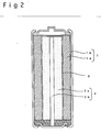
- the positive electrode agent in each of the embodiment 1 and the comparative examples 1 to 6 was used for the positive electrode, while a kneaded mixture of zinc oxide having an average particle diameter of 0.4 ⁇ m, zinc having an average particle diameter of 120 ⁇ m, indium hydroxide for suppressing oxygen gas evolution, and polytetrafluoroethylene serving as a binder in a weight ratio of 60 : 35 : 3 : 2 was used as the negative electrode agent at the negative electrode, thereby fabricating an alkali storage battery having an inside out structure as shown in Fig. 2.
- the above-mentioned positive electrode agent 1a was formed in a cylindrical shape and was inserted into a positive electrode can 1b, to construct a positive electrode 1, while an alkali solution as an electrolyte was impregnated in a separator 3 obtained by laminating cellophane and a polyolefin nonwoven fabric, the separator 3 was provided around a hollow portion at the center of the positive electrode 1, the hollow portion of the positive electrode 1 was filled with the above-mentioned negative electrode agent 2a through the separator 3, and a negative electrode collector 2b in the shape of a stick was arranged at its central part to construct a negative electrode 2, thereby fabricating an alkali storage battery having an inside out structure.
- Each of the alkali storage batteries in the embodiment 1 and the comparative examples 1 to 6 fabricated in the above-mentioned manner was then charged with constant current of 100 mA up to 1.95 V, was preserved at a temperature of 40°C for one week, and was then discharged with constant current of 100 mA up to 1.0 V to measure a charging capacity C1 and a discharging capacity C2 as well as to find the ratio of the discharging capacity C2 to the charging capacity C1 (C2/C1). Further, 10 alkali storage batteries in each of the embodiment 1 and the comparative examples 1 to 6 were used, and were charged and discharged, as described above, to find the number of alkali storage batteries from which an electrolyte leaks. The results were shown in the following Table 2.
- the ratio of the discharging capacity C2 to the charging capacity C1 (C2/C1) was higher, as compared with that in each of the alkali storage batteries in the comparative examples 1 to 6, and leakage of an electrolyte as in each of the alkali storage batteries in the comparative examples 1 to 6 did not occur.
- the alkali storage battery in the above-mentioned embodiment 1 was used, and was charged and discharged in the same manner as that in the above-mentioned case except that a charging final voltage was changed as shown in the following Table 3 in charging the battery with constant current of 100 mA, and a charging capacity C1 and a discharging capacity C2 were measured, to find the ratio of the discharging capacity to the charging capacity C1 (C2/C1). Further, 10 alkali storage batteries were charged and discharged, as described above, to find the number of batteries from which an electrolyte leaks. The results were shown in Table 3.
- the charging final voltage 120 In order to increase the charging and discharging efficiency while preventing an electrolyte from leaking as well as to make the decrease in the battery capacity slight, therefore, it was preferable to make the charging final voltage 120 to 300 mV lower than 2.13 V which is an oxygen gas evolution potential. In order to make the decrease in the battery capacity slighter, it was preferable to make the charging final voltage 120 to 180 mV lower than the oxygen gas evolution potential.
- nickel sulfate and manganese sulfate were used, as in the above-mentioned embodiment 1.
- the mixture ratio of nickel sulfate to manganese sulfate was changed, to obtain cathode active materials composed of ⁇ -nickel hydroxide containing manganese whose amount was 7 mole %, 8 mole %, 10 mole %, 15 mole %, 25 mole %, 40 mole %, 60 mole %, and 70 mole %.
- Positive electrode agents were respectively prepared in the same manner as that in the above-mentioned embodiment 1 using the above-mentioned cathode active materials, and batteries for testing were respectively fabricated in the same manner as that in the above-mentioned case using the positive electrode agents thus prepared, to measure the above-mentioned oxygen gas evolution potential V1 and charging potential V2 at each of the positive electrodes for testing, find the difference (V1 - V2) between the oxygen gas evolution potential and the charging potential, and further find the number of exchanged electrons related to reaction on the basis of one mole of the nickel atom in the cathode active material and find the number of excahged electrons related to reaction on the basis of one mole of the sum of the nickel atom and the manganese atom.
- Alkali storage batteries having an inside out structure as shown in Fig. 2 were respectively fabricated in the same manner as that in the above-mentioned embodiment 1 using the above-mentioned cathode active materials containing manganese whose amount was changed.
- Each of the alkali storage batteries thus fabricated was charged with constant current of 100 mA up to 1.95 V, was preserved at a temperature of 40 °C for one week, and was then discharged with constant current of 100 mA up to 1.0 V, after which the discharging was stopped for one hour.
- the above-mentioned charging and discharging were considered as one cycle. 20 cycles of charging and discharging were performed, to find a discharging capacity Q1 at the first cycle time and a discharging capacity Q20 at the 20-th cycle time as well as to calculate the percentage of capacity retention at the 20-th cycle time on the basis of the following equation. The results were shown in the following Table 5.
- Percentage of capacity retention ( Q 20 / Q 1 ) ⁇ 100 (Table 5) amount of Mn (mole %) discharging capacity (mAh) percentage of capacity retention at 20-th cycle time (%) first cycle time 20-th cycle time 7 1600 980 61 8 1630 1380 85 10 1640 1460 89 15 1620 1550 96 25 1580 1510 96 40 1480 1450 98 60 1240 1200 97 70 980 950 97
- the amount of manganese in the cathode active material was preferably in the range of 8 to 60 mole %, and more preferably in the range of 15 to 40 mole %.
- ⁇ -nickel hydroxide containing manganese is used as a cathode active material for a positive electrode of the alkali storage battery. Therefore, the difference between an oxygen gas evolution potential and a charging potential at the positive electrode is increased, the alkali storage battery is simply charged to a predetermined voltage while suppressing oxygen gas evolution without decreasing a voltage in the alkali storage battery, and the range of a voltage at which charging and discharging can be performed is widened, so that a large battery capacity is obtained, and charge/discharge cycle performance is also improved.
- the battery can be simply charged to a predetermined potential while suppressing oxygen gas evolution as described above.
- the battery can be simply charged to a predetermined potential while suppressing oxygen gas evolution as described above.
- it is possible to fabricate a battery having an inside out structure to increase the energy density of the battery without enlarging a void inside the battery and increasing the area of its negative electrode such that oxygen gas is absorbed at the negative electrode as in the conventional example.
Landscapes
- Chemical & Material Sciences (AREA)
- Chemical Kinetics & Catalysis (AREA)
- Electrochemistry (AREA)
- General Chemical & Material Sciences (AREA)
- Engineering & Computer Science (AREA)
- Manufacturing & Machinery (AREA)
- Inorganic Chemistry (AREA)
- Battery Electrode And Active Subsutance (AREA)
- Secondary Cells (AREA)
Claims (12)
- Alkalische Speicherbatterie mit einer positiven Elektrode (1), einer negativen Elektrode (2) und einem alkalischen Elektrolyten in einem Batteriebehälter, wobei α-Nickelhydroxid, das Mangan enthält, als aktives Kathodenmaterial für die positive Elektrode (1) verwendet wird, und dadurch gekennzeichnet, dass der Volumenanteil des aktiven Kathodenmaterials und des aktiven Anodenmaterials für die negative Elektrode (2) nicht weniger als 75% in dem Batteriebehälter beträgt, wobei der Anteil von Mangan in dem aktiven Kathodenmaterial im Bereich von 8 bis 60 Mol- % liegt.
- Alkalische Speicherbatterie nach Anspruch 1, dadurch gekennzeichnet, dass die positive Elektrode (1) und die negative Elektrode (2) auf der Außenseite eines Separators (3) bzw. auf der Innenseite des Separators angeordnet sind.
- Alkalische Speicherbatterie nach Anspruch 1, dadurch gekennzeichnet, dass der Inhalt von Mangan in dem Aktivkathodenmaterial im Bereich von 15 bis 40 Mol-% liegt.
- Alkalische Speicherbatterie nach Anspruch 1, dadurch gekennzeichnet, dass das Ladepotential (V2) an der positiven Elektrode (1) um 120 bis 300 mV geringer ist als ein Sauerstoffgasentwicklungspotential (V1) an der positiven Elektrode (1).
- Alkalische Speicherbatterie nach Anspruch 1, dadurch gekennzeichnet, dass das Ladepotential (V2) an der positiven Elektrode (1) um 120 bis 180 mV geringer ist als das Sauerstoffgasentwicklungspotential (V1) an der positiven Elektrode (1).
- Alkalische Speicherbatterie nach Anspruch 1, dadurch gekennzeichnet, dass Zink als aktives Anodenmaterial für die negative Elektrode (2) verwendet wird.
- Ladeverfahren für eine alkalische Speicherbatterie, wobei eine alkalische Speicherbatterie geladen wird, die α-Nickelhydroxid, das Mangan enthält, als aktives Kathodenmaterial für ihre positive Elektrode (1) verwendet, das Laden bei einem Potential (V2) beendet wird, das geringer ist als ein Sauerstoffgasentwicklungspotential (V1) an der positiven Elektrode (1), wobei der Anteil von Mangan in dem aktiven Kathodenmaterial im Bereich von 8 bis 60 Mol- % liegt.
- Ladeverfahren für die alkalische Speicherbatterie nach Anspruch 7, dadurch gekennzeichnet, dass das Potential (V2) an der positiven Elektrode (1), bei dem das Laden beendet wird, um 120 bis 300 mV geringer ist als das Sauerstoffgasentwicklungspotential (V1) an der positiven Elektrode (1).
- Ladeverfahren für die alkalische Speicherbatterie nach Anspruch 7, dadurch gekennzeichnet, dass das Potential (V2) an der positiven Elektrode (1), bei dem das Laden beendet wird, um 120 bis 180 mV geringer ist als das Sauerstoffgasentwicklungspotential (V1) an der positiven Elektrode (1).
- Ladeverfahren für die alkalische Speicherbatterie nach Anspruch 7, dadurch gekennzeichnet, dass der Anteil von Mangan in dem aktiven Kathodenmaterial im Bereich von 15 bis 40 Mol- % liegt.
- Ladeverfahren für die alkalische Speicherbatterie nach Anspruch 7, dadurch gekennzeichnet, dass die Batterie mit einem vorgegebenen Strom auf ein Potential geladen wird, das geringer ist als der Sauerstoffgasentwicklungspotential (V1) an der positiven Elektrode (1).
- Ladeverfahren für die alkalische Speicherbatterie nach Anspruch 7, dadurch gekennzeichnet, dass der Wert eines Stroms, bei dem die Batterie auf ein vorgegebenes Potential geladen wird, geändert wird, um die Batterie auf ein Potential zu laden, das geringer ist als das Sauerstoffgasentwicklungspotential (V1) an der positiven Elektrode (1).
Applications Claiming Priority (3)
| Application Number | Priority Date | Filing Date | Title |
|---|---|---|---|
| JP179697 | 1997-01-09 | ||
| JP179697 | 1997-01-09 | ||
| PCT/JP1997/004774 WO1998031063A1 (en) | 1997-01-09 | 1997-12-22 | Alkaline storage battery and method for charging battery |
Publications (3)
| Publication Number | Publication Date |
|---|---|
| EP0952621A1 EP0952621A1 (de) | 1999-10-27 |
| EP0952621A4 EP0952621A4 (de) | 2004-09-29 |
| EP0952621B1 true EP0952621B1 (de) | 2006-09-20 |
Family
ID=11511542
Family Applications (1)
| Application Number | Title | Priority Date | Filing Date |
|---|---|---|---|
| EP97949220A Expired - Lifetime EP0952621B1 (de) | 1997-01-09 | 1997-12-22 | Alkalische speicherbatterie und verfahren zum laden dieser batterie |
Country Status (8)
| Country | Link |
|---|---|
| US (1) | US6077626A (de) |
| EP (1) | EP0952621B1 (de) |
| JP (1) | JP3389252B2 (de) |
| KR (1) | KR100386874B1 (de) |
| CN (1) | CN1226801C (de) |
| CA (1) | CA2272386C (de) |
| DE (1) | DE69736718T2 (de) |
| WO (1) | WO1998031063A1 (de) |
Families Citing this family (9)
| Publication number | Priority date | Publication date | Assignee | Title |
|---|---|---|---|---|
| US6235428B1 (en) * | 1997-01-30 | 2001-05-22 | Sanyo Electric Co., Ltd. | Enclosed alkali storage battery |
| US6265101B1 (en) | 1998-08-21 | 2001-07-24 | Eveready Battery Company, Inc. | Battery constructions having increased internal volume for active components |
| USRE38518E1 (en) | 1998-08-21 | 2004-05-18 | Eveready Battery Company, Inc. | Battery constructions having increased internal volume for active components |
| JP4049484B2 (ja) * | 1999-08-02 | 2008-02-20 | 三洋電機株式会社 | 密閉型アルカリ蓄電池 |
| DE10045622A1 (de) * | 2000-09-15 | 2002-03-28 | Nbt Gmbh | Verfahren zur Überwachung der Ladung gasdichter alkalischer Akkumulatoren |
| US6991875B2 (en) * | 2002-08-28 | 2006-01-31 | The Gillette Company | Alkaline battery including nickel oxyhydroxide cathode and zinc anode |
| US7527890B2 (en) | 2003-01-31 | 2009-05-05 | Yuasa Corporation | Sealed alkaline storage battery, electrode structure and charging method for the same, and charger for sealed alkaline storage battery |
| CN102013527B (zh) * | 2009-09-08 | 2012-08-29 | 清华大学深圳研究生院 | 可充电锌离子电池 |
| CN117712515B (zh) * | 2024-01-04 | 2025-03-28 | 德之昭科技(苏州)有限公司 | 一种碱性铁锰蓄电池 |
Citations (1)
| Publication number | Priority date | Publication date | Assignee | Title |
|---|---|---|---|---|
| EP0712174A2 (de) * | 1994-11-09 | 1996-05-15 | H.C. Starck GmbH & Co. KG | Mangan-haltige Nickel(II)-hydroxid-Pulver, Verfahren zu ihrer Herstellung sowie deren Verwendung |
Family Cites Families (14)
| Publication number | Priority date | Publication date | Assignee | Title |
|---|---|---|---|---|
| JPS5828181A (ja) * | 1981-08-13 | 1983-02-19 | Furukawa Battery Co Ltd:The | 密閉型ニツケル・カドミウム蓄電池の充電方式 |
| DE68926642T2 (de) * | 1988-01-22 | 1996-11-28 | Japan Storage Battery Co Ltd | Alkalische batterien und verfahren zur herstellung |
| US5071722A (en) * | 1989-02-15 | 1991-12-10 | Japan Storage Battery Co., Ltd. | Process for preparing cadmium hydroxide, and alkaline secondary battery and method for charging the same |
| JP2898421B2 (ja) * | 1991-01-16 | 1999-06-02 | 日立マクセル株式会社 | アルカリ二次電池用の焼結式ニッケル電極の製造方法 |
| JP3092222B2 (ja) * | 1991-07-08 | 2000-09-25 | 松下電器産業株式会社 | 水酸化ニッケル活物質およびニッケル正極とこれを用いたアルカリ蓄電池 |
| US5700596A (en) * | 1991-07-08 | 1997-12-23 | Matsushita Electric Industrial Co., Ltd. | Nickel hydroxide active material powder and nickel positive electrode and alkali storage battery using them |
| JP3136668B2 (ja) * | 1991-07-08 | 2001-02-19 | 松下電器産業株式会社 | 水酸化ニッケル活物質粉末およびニッケル正極とこれを用いたアルカリ蓄電池 |
| JP3200822B2 (ja) * | 1991-10-24 | 2001-08-20 | 日本電池株式会社 | ニッケル−金属水素化物蓄電池 |
| US5567549A (en) * | 1992-11-12 | 1996-10-22 | Ovonic Battery Company, Inc. | Nickel metal hydride battery containing a modified disordered multiphase nickel aluminum based positive electrode |
| US5569563A (en) * | 1992-11-12 | 1996-10-29 | Ovshinsky; Stanford R. | Nickel metal hybride battery containing a modified disordered multiphase nickel hydroxide positive electrode |
| DE4323007C2 (de) * | 1993-07-09 | 1995-06-08 | Starck H C Gmbh Co Kg | Mangan(III)-haltiges Nickel(II)-hydroxid, ein Verfahren zu seiner Herstellung sowie seine Verwendung als Elektrodenmaterial für Sekundärbatterien |
| JPH0745281A (ja) * | 1993-07-29 | 1995-02-14 | Yuasa Corp | アルカリ蓄電池用ニッケル電極とこれを用いたアルカリ蓄電池 |
| JP3373957B2 (ja) * | 1994-10-18 | 2003-02-04 | 三洋電機株式会社 | ニッケル・水素化物アルカリ蓄電池 |
| US5905003A (en) * | 1995-06-26 | 1999-05-18 | Energy Conversion Devices, Inc. | Beta to gamma phase cycleable electrochemically active nickel hydroxide material |
-
1997
- 1997-12-22 KR KR10-1999-7006091A patent/KR100386874B1/ko not_active Expired - Fee Related
- 1997-12-22 JP JP53073198A patent/JP3389252B2/ja not_active Expired - Fee Related
- 1997-12-22 CN CNB971812586A patent/CN1226801C/zh not_active Expired - Fee Related
- 1997-12-22 DE DE69736718T patent/DE69736718T2/de not_active Expired - Lifetime
- 1997-12-22 WO PCT/JP1997/004774 patent/WO1998031063A1/ja not_active Ceased
- 1997-12-22 US US09/284,860 patent/US6077626A/en not_active Expired - Lifetime
- 1997-12-22 CA CA002272386A patent/CA2272386C/en not_active Expired - Fee Related
- 1997-12-22 EP EP97949220A patent/EP0952621B1/de not_active Expired - Lifetime
Patent Citations (1)
| Publication number | Priority date | Publication date | Assignee | Title |
|---|---|---|---|---|
| EP0712174A2 (de) * | 1994-11-09 | 1996-05-15 | H.C. Starck GmbH & Co. KG | Mangan-haltige Nickel(II)-hydroxid-Pulver, Verfahren zu ihrer Herstellung sowie deren Verwendung |
Also Published As
| Publication number | Publication date |
|---|---|
| CA2272386A1 (en) | 1998-07-16 |
| CN1244295A (zh) | 2000-02-09 |
| CA2272386C (en) | 2004-11-30 |
| JP3389252B2 (ja) | 2003-03-24 |
| EP0952621A4 (de) | 2004-09-29 |
| CN1226801C (zh) | 2005-11-09 |
| EP0952621A1 (de) | 1999-10-27 |
| WO1998031063A1 (en) | 1998-07-16 |
| US6077626A (en) | 2000-06-20 |
| KR100386874B1 (ko) | 2003-06-11 |
| KR20000069898A (ko) | 2000-11-25 |
| DE69736718D1 (de) | 2006-11-02 |
| DE69736718T2 (de) | 2007-09-13 |
Similar Documents
| Publication | Publication Date | Title |
|---|---|---|
| EP0544011B1 (de) | Nickelelektrode für alkalibatterien | |
| EP1195832A1 (de) | Hochtemperatur nickel-wasserstoffbatterie und verfahren zu deren herstellung | |
| EP0952621A1 (de) | Alkalische speicherbatterie und verfahren zum laden dieser batterie | |
| EP1958278B1 (de) | Wiederaufladbare alkali-mangan-zelle mit verringertem kapazitäts-fading und verbesserter zykluslebensdauer | |
| JP3568408B2 (ja) | アルカリ二次電池用正極活物質及びアルカリ二次電池 | |
| JP4243449B2 (ja) | アルカリ一次電池 | |
| JPWO1998031063A1 (ja) | アルカリ蓄電池及びその充電方法 | |
| KR100404658B1 (ko) | 니켈-금속수소화물축전지및그제조방법 | |
| JP3338361B2 (ja) | アルカリ二次電池 | |
| US6881519B2 (en) | Ni/metal hydride secondary element | |
| JP2966627B2 (ja) | 金属水素化物蓄電池 | |
| EP1139465B1 (de) | Alkalische Speicherbatterie und Verfahren zu ihrer Herstellung | |
| JP2517936B2 (ja) | 空気亜鉛電池 | |
| JP3200822B2 (ja) | ニッケル−金属水素化物蓄電池 | |
| JP3454641B2 (ja) | アルカリ蓄電池用カドミウム負極およびその製造方法 | |
| JP2591988B2 (ja) | カドミウム負極板およびその負極板を用いたアルカリ二次電池 | |
| JP3101622B2 (ja) | ニッケル・水素アルカリ蓄電池 | |
| EP1755181A1 (de) | Alkali-speicherbatterie | |
| JP2000251924A (ja) | 密閉型アルカリ亜鉛蓄電池 | |
| JP2600307B2 (ja) | カドミウム負極板およびその負極板を用いたアルカリ二次電池 | |
| JP2000106184A (ja) | アルカリ蓄電池用水酸化ニッケル電極とその電極を用いたアルカリ蓄電池 | |
| JP2591986B2 (ja) | カドミウム負極板およびその負極板を用いたアルカリ二次電池 | |
| JPH103940A (ja) | ニッケル−金属水素化物蓄電池及びその製造方法 | |
| JP2591987B2 (ja) | カドミウム負極板およびその負極板を用いたアルカリ二次電池 | |
| JP2000251883A (ja) | 密閉型アルカリ亜鉛蓄電池 |
Legal Events
| Date | Code | Title | Description |
|---|---|---|---|
| PUAI | Public reference made under article 153(3) epc to a published international application that has entered the european phase |
Free format text: ORIGINAL CODE: 0009012 |
|
| 17P | Request for examination filed |
Effective date: 19990708 |
|
| AK | Designated contracting states |
Kind code of ref document: A1 Designated state(s): BE DE FR GB |
|
| A4 | Supplementary search report drawn up and despatched |
Effective date: 20040812 |
|
| GRAJ | Information related to disapproval of communication of intention to grant by the applicant or resumption of examination proceedings by the epo deleted |
Free format text: ORIGINAL CODE: EPIDOSDIGR1 |
|
| GRAP | Despatch of communication of intention to grant a patent |
Free format text: ORIGINAL CODE: EPIDOSNIGR1 |
|
| GRAP | Despatch of communication of intention to grant a patent |
Free format text: ORIGINAL CODE: EPIDOSNIGR1 |
|
| GRAS | Grant fee paid |
Free format text: ORIGINAL CODE: EPIDOSNIGR3 |
|
| GRAA | (expected) grant |
Free format text: ORIGINAL CODE: 0009210 |
|
| RIN1 | Information on inventor provided before grant (corrected) |
Inventor name: NISHIO, KOJI Inventor name: YONEZU, IKUO Inventor name: MAEDA, REIZO Inventor name: FUJITANI, SHIN Inventor name: SUZUKI, SYUICHI Inventor name: TOKUDA, MITSUNORI Inventor name: YANO, MUTSUMI Inventor name: NOGAMI, MITSUZOU |
|
| AK | Designated contracting states |
Kind code of ref document: B1 Designated state(s): BE DE FR GB |
|
| PG25 | Lapsed in a contracting state [announced via postgrant information from national office to epo] |
Ref country code: BE Free format text: LAPSE BECAUSE OF FAILURE TO SUBMIT A TRANSLATION OF THE DESCRIPTION OR TO PAY THE FEE WITHIN THE PRESCRIBED TIME-LIMIT Effective date: 20060920 |
|
| REG | Reference to a national code |
Ref country code: GB Ref legal event code: FG4D |
|
| REF | Corresponds to: |
Ref document number: 69736718 Country of ref document: DE Date of ref document: 20061102 Kind code of ref document: P |
|
| ET | Fr: translation filed | ||
| PLBE | No opposition filed within time limit |
Free format text: ORIGINAL CODE: 0009261 |
|
| STAA | Information on the status of an ep patent application or granted ep patent |
Free format text: STATUS: NO OPPOSITION FILED WITHIN TIME LIMIT |
|
| 26N | No opposition filed |
Effective date: 20070621 |
|
| PGFP | Annual fee paid to national office [announced via postgrant information from national office to epo] |
Ref country code: GB Payment date: 20121219 Year of fee payment: 16 |
|
| PGFP | Annual fee paid to national office [announced via postgrant information from national office to epo] |
Ref country code: FR Payment date: 20130107 Year of fee payment: 16 |
|
| PGFP | Annual fee paid to national office [announced via postgrant information from national office to epo] |
Ref country code: DE Payment date: 20121219 Year of fee payment: 16 |
|
| REG | Reference to a national code |
Ref country code: DE Ref legal event code: R119 Ref document number: 69736718 Country of ref document: DE |
|
| GBPC | Gb: european patent ceased through non-payment of renewal fee |
Effective date: 20131222 |
|
| REG | Reference to a national code |
Ref country code: DE Ref legal event code: R119 Ref document number: 69736718 Country of ref document: DE Effective date: 20140701 |
|
| REG | Reference to a national code |
Ref country code: FR Ref legal event code: ST Effective date: 20140829 |
|
| PG25 | Lapsed in a contracting state [announced via postgrant information from national office to epo] |
Ref country code: DE Free format text: LAPSE BECAUSE OF NON-PAYMENT OF DUE FEES Effective date: 20140701 |
|
| PG25 | Lapsed in a contracting state [announced via postgrant information from national office to epo] |
Ref country code: GB Free format text: LAPSE BECAUSE OF NON-PAYMENT OF DUE FEES Effective date: 20131222 Ref country code: FR Free format text: LAPSE BECAUSE OF NON-PAYMENT OF DUE FEES Effective date: 20131231 |