EP0952630B1 - Connecteur électrique pour des circuits plats flexibles - Google Patents
Connecteur électrique pour des circuits plats flexibles Download PDFInfo
- Publication number
- EP0952630B1 EP0952630B1 EP99107251A EP99107251A EP0952630B1 EP 0952630 B1 EP0952630 B1 EP 0952630B1 EP 99107251 A EP99107251 A EP 99107251A EP 99107251 A EP99107251 A EP 99107251A EP 0952630 B1 EP0952630 B1 EP 0952630B1
- Authority
- EP
- European Patent Office
- Prior art keywords
- connector
- body member
- flexible circuit
- circuit
- length
- Prior art date
- Legal status (The legal status is an assumption and is not a legal conclusion. Google has not performed a legal analysis and makes no representation as to the accuracy of the status listed.)
- Expired - Lifetime
Links
- 239000004020 conductor Substances 0.000 claims description 16
- 239000004033 plastic Substances 0.000 claims description 10
- 230000000295 complement effect Effects 0.000 claims description 9
- 239000013536 elastomeric material Substances 0.000 claims description 9
- 229920002379 silicone rubber Polymers 0.000 claims description 9
- 239000004945 silicone rubber Substances 0.000 claims description 9
- 239000000463 material Substances 0.000 claims description 8
- 230000013011 mating Effects 0.000 claims description 8
- 239000003989 dielectric material Substances 0.000 description 2
- 239000011241 protective layer Substances 0.000 description 2
- 206010035148 Plague Diseases 0.000 description 1
- 241000607479 Yersinia pestis Species 0.000 description 1
- 230000001668 ameliorated effect Effects 0.000 description 1
- 239000013070 direct material Substances 0.000 description 1
- 230000037431 insertion Effects 0.000 description 1
- 238000003780 insertion Methods 0.000 description 1
- 239000000758 substrate Substances 0.000 description 1
Images


Classifications
-
- H—ELECTRICITY
- H01—ELECTRIC ELEMENTS
- H01R—ELECTRICALLY-CONDUCTIVE CONNECTIONS; STRUCTURAL ASSOCIATIONS OF A PLURALITY OF MUTUALLY-INSULATED ELECTRICAL CONNECTING ELEMENTS; COUPLING DEVICES; CURRENT COLLECTORS
- H01R12/00—Structural associations of a plurality of mutually-insulated electrical connecting elements, specially adapted for printed circuits, e.g. printed circuit boards [PCB], flat or ribbon cables, or like generally planar structures, e.g. terminal strips, terminal blocks; Coupling devices specially adapted for printed circuits, flat or ribbon cables, or like generally planar structures; Terminals specially adapted for contact with, or insertion into, printed circuits, flat or ribbon cables, or like generally planar structures
- H01R12/70—Coupling devices
- H01R12/77—Coupling devices for flexible printed circuits, flat or ribbon cables or like structures
- H01R12/771—Details
- H01R12/772—Strain relieving means
-
- H—ELECTRICITY
- H01—ELECTRIC ELEMENTS
- H01R—ELECTRICALLY-CONDUCTIVE CONNECTIONS; STRUCTURAL ASSOCIATIONS OF A PLURALITY OF MUTUALLY-INSULATED ELECTRICAL CONNECTING ELEMENTS; COUPLING DEVICES; CURRENT COLLECTORS
- H01R11/00—Individual connecting elements providing two or more spaced connecting locations for conductive members which are, or may be, thereby interconnected, e.g. end pieces for wires or cables supported by the wire or cable and having means for facilitating electrical connection to some other wire, terminal, or conductive member, blocks of binding posts
-
- H—ELECTRICITY
- H01—ELECTRIC ELEMENTS
- H01R—ELECTRICALLY-CONDUCTIVE CONNECTIONS; STRUCTURAL ASSOCIATIONS OF A PLURALITY OF MUTUALLY-INSULATED ELECTRICAL CONNECTING ELEMENTS; COUPLING DEVICES; CURRENT COLLECTORS
- H01R12/00—Structural associations of a plurality of mutually-insulated electrical connecting elements, specially adapted for printed circuits, e.g. printed circuit boards [PCB], flat or ribbon cables, or like generally planar structures, e.g. terminal strips, terminal blocks; Coupling devices specially adapted for printed circuits, flat or ribbon cables, or like generally planar structures; Terminals specially adapted for contact with, or insertion into, printed circuits, flat or ribbon cables, or like generally planar structures
- H01R12/70—Coupling devices
- H01R12/77—Coupling devices for flexible printed circuits, flat or ribbon cables or like structures
- H01R12/79—Coupling devices for flexible printed circuits, flat or ribbon cables or like structures connecting to rigid printed circuits or like structures
-
- H—ELECTRICITY
- H01—ELECTRIC ELEMENTS
- H01R—ELECTRICALLY-CONDUCTIVE CONNECTIONS; STRUCTURAL ASSOCIATIONS OF A PLURALITY OF MUTUALLY-INSULATED ELECTRICAL CONNECTING ELEMENTS; COUPLING DEVICES; CURRENT COLLECTORS
- H01R12/00—Structural associations of a plurality of mutually-insulated electrical connecting elements, specially adapted for printed circuits, e.g. printed circuit boards [PCB], flat or ribbon cables, or like generally planar structures, e.g. terminal strips, terminal blocks; Coupling devices specially adapted for printed circuits, flat or ribbon cables, or like generally planar structures; Terminals specially adapted for contact with, or insertion into, printed circuits, flat or ribbon cables, or like generally planar structures
- H01R12/70—Coupling devices
- H01R12/82—Coupling devices connected with low or zero insertion force
- H01R12/85—Coupling devices connected with low or zero insertion force contact pressure producing means, contacts activated after insertion of printed circuits or like structures
- H01R12/87—Coupling devices connected with low or zero insertion force contact pressure producing means, contacts activated after insertion of printed circuits or like structures acting automatically by insertion of rigid printed or like structures
-
- H—ELECTRICITY
- H01—ELECTRIC ELEMENTS
- H01R—ELECTRICALLY-CONDUCTIVE CONNECTIONS; STRUCTURAL ASSOCIATIONS OF A PLURALITY OF MUTUALLY-INSULATED ELECTRICAL CONNECTING ELEMENTS; COUPLING DEVICES; CURRENT COLLECTORS
- H01R13/00—Details of coupling devices of the kinds covered by groups H01R12/70 or H01R24/00 - H01R33/00
- H01R13/46—Bases; Cases
- H01R13/50—Bases; Cases formed as an integral body
- H01R13/501—Bases; Cases formed as an integral body comprising an integral hinge or a frangible part
-
- H—ELECTRICITY
- H01—ELECTRIC ELEMENTS
- H01R—ELECTRICALLY-CONDUCTIVE CONNECTIONS; STRUCTURAL ASSOCIATIONS OF A PLURALITY OF MUTUALLY-INSULATED ELECTRICAL CONNECTING ELEMENTS; COUPLING DEVICES; CURRENT COLLECTORS
- H01R13/00—Details of coupling devices of the kinds covered by groups H01R12/70 or H01R24/00 - H01R33/00
- H01R13/62—Means for facilitating engagement or disengagement of coupling parts or for holding them in engagement
- H01R13/627—Snap or like fastening
- H01R13/6271—Latching means integral with the housing
- H01R13/6273—Latching means integral with the housing comprising two latching arms
Definitions
- This invention generally relates to the art of electrical connectors and, particularly, to connectors for electrically interconnecting flat flexible circuitry.
- a flat flexible circuit conventionally includes an elongated flat flexible dielectric substrate having laterally spaced strips of conductors on one or both sides thereof.
- the conductors may be covered with a thin, flexible protective layer on one or both sides of the circuit. If protective layers are used, cutouts are formed therein to expose the underlying conductors at desired contact locations where the conductors are to engage the conductors of a complementary mating connecting device which may be a second flat flexible circuit, a printed circuit board or the terminals of a mating connector.
- US 5,009,607 discloses a flexible circuit connector according to the pre-characterizing portion of claim 1 which is used to electrically and mechanically connect a flexible circuit to a circuit board or other electronic device.
- the present invention is directed to solving these problems by providing an extremely simple, inexpensive and reliable connector structure not heretofore available.
- a newand improved connector for electrically interconnecting the conductors of a flat flexible circuit to the conductors of a complementary mating connecting device.
- the connector includes a body member on which a first length of the flexible circuit is fixed, with a second length of the circuit extending away from the body member.
- a resilient strain relief means is provided on the body member engageable with the flexible circuit such as to locate the second length of the flexible circuit in a plane offset from the plane of the first length of the circuit. Therefore, pulling forces on the second length of the flexible circuit away from the body member biases the circuit against the resilient strain relief means.
- the body member includes a passage through which the second length of the flexible circuit extends.
- the passage is offset from the plane of the first length of the circuit.
- the resilient strain relief means is located in the passage.
- the body member is disposed herein as being elongated, and the passage is formed by a relatively narrow slot extending lengthwise of the body member.
- the body member is shown herein as a unitarily molded structure of plastic material, and the strain relief means is a molded-in-place component of an elastomeric material.
- the body member preferably is molded of relatively rigid plastic material, and the strain relief means may be of silicone rubber.
- the invention also contemplates the connector including a multi-part housing for receiving the flat flexible circuit.
- the housing includes at least a pair of rigid housing parts relatively movable between open and closed positions.
- a flexible hinge means is molded between the rigid housing parts to accommodate the movement of the housing parts between their positions.
- the flexible hinge means comprises at least one molded-in-place component of elastomeric material such as silicone rubber.
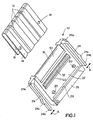
- a first embodiment of a male connector is shown for electrically interconnecting the conductors 12 of a flat flexible circuit or cable 14 to the conductors of a complementary mating connecting device (not shown).
- male connector 10 can be mated with a complementary female connector by inserting a leading edge 16 of the male connector into an appropriate receptacle of the female connector.
- the male connector could be connected to another complementary male connector.
- flat flexible circuit 14 is wrapped around leading edge 16 of the connector, and locating holes 18 in the circuit are positioned over locating pegs 20 on opposite sides of the male connector.
- male connector 10 includes a male body member 22 about which flat flexible circuit 14 is wrapped.
- the male body member is generally flat and elongated and includes a pair of cantilevered latch arms 24 at opposite ends thereof.
- the body member, including the latch arms, is unitarily molded of relatively rigid dielectric material such as plastic or the like.
- Cantilevered latch arms 24 are joined to the body member at proximal ends 24a of the latch arms near opposite ends of leading edge 16 of the connector. Therefore, free ends 24b of the latch arms can flex in the direction of doubleheaded arrows "A".
- a pair of latch hooks 24c project outwardly of latch arms 24 for engagement with appropriate latch means on the complementary mating connecting device.
- a raised rib or flange 26 extends longitudinally along the top rear edge of the body member to define a slot 28 therebeneath and through which flat flexible circuit 14 extends, as best seen in Figure 5 described hereinafter.
- the invention contemplates the provision of resilient means in the form of an elongated resilient component 30 which extends along and defines leading edge 16 of the connector for spring loading flexible circuit 14 to enhance the engagement thereof with locating pegs 20.
- Resilient component 30 is a molded-in-place strip fabricated of elastomeric material, such as silicone rubber.
- connector 10 (Figs. 1 and 2) includes a molded-in-place resilient backing rib 32 (Fig. 1) which extends longitudinally of the width of body member 22 and engages the underside of flexible circuit 14 to bias conductors 12 of the circuit against the conductors of the complementary mating connecting device.
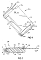
- Figures 3-5 show a second embodiment of a male connector, generally designated 10A, which is substantially identical to connector 10 (Figs. 1 and 2) except that connector 10A includes a resilient strain relief member 33 on the underside of flange 26 as best seen in Figure 5. Consequently, like numerals have been applied in Figures 3-5 designating like components of male connector 10A corresponding to the components described above in relation to connector 10 in Figures 1 and 2.
- flange 26 is a separate rigid plastic component joined to body member 22 by a living hinge 34.
- the living hinge is a molded-in-place component of elastomeric material such as silicone rubber.
- the opposite end of separate flange 26 has a hooked latch 35a for latching over a surface 35b of body member 22. Therefore, the flange can be unlatched to open slot 28 significantly to enable easy positioning of the flexible circuit in the slot.
- Figure 5 clearly shows how resilient component 30 is molded-in-place about a leading edge 22a of body member 22. It also can be seen how flexible circuit 14 is wrapped around leading edge 16 of the connector defined by resilient component 30.
- the invention contemplates that locating holes 18 (Fig. 1) in flexible circuit 14 be spaced such that, when the holes are positioned about locating pegs 20 as seen in Figure 5, the flexible circuit will be wrapped tightly about resilient component 30, even to the extent of slightly compressing the resilient component in the direction of arrow "B". Therefore, the resilient component is effective to spring load the flexible circuit to enhance the engagement thereof with locating pegs 20. In other words, the resilient component is effective to take out any looseness or slack in the flexible circuit which, otherwise, might simply fall off of the locating pegs.
- a first length 14a of the circuit is disposed on top of body member 22, and a second length 14b of the circuit extends beneath flange 26 and away from the rear of the body member. It can be seen that the second length 14b of the circuit is in a plane offset from the plane of the first length 14a of the circuit.
- Resilient strain relief member 33 engages the top of length 14b of the circuit in its plane offset from length 14a of the circuit.
- resilient strain relief member 33 is a molded-in-place structure on the underside of flange 26 and is fabricated of such elastomeric material as silicone rubber.
- connector 10B for interconnecting the conductors 40 on opposite sides of a flat flexible circuit, generally designated 42, to the circuit traces on opposite sides of a printed circuit board 44 as seen in Figures 7 and 8.
- connector 10B includes a multi-part housing, generally designated 46, which is formed by a pair of rigid housing parts 48 and 50.
- Each housing part is a one-piece structure unitarily molded of dielectric material such as rigid plastic.
- the housing parts are movable between open positions shown in Figure 6 to facilitate loading of flexible circuit 42, and closed positions shown in Figures 7 and 8 for interconnecting the conductors of the flexible circuit to the circuit traces of printed circuit board 44.
- the housing parts have complementarily interengaging latch arms 52 which are flexible and molded integrally with the housing parts.
- the latch arms are cantilevered and include complementarily interengaging latch hooks 52a when the housing parts are in their closed positions.
- Housing part 50 has an elongated slot 54 for the passage therethrough of flexible circuit 42 as best seen in Figure 8.
- each housing part includes a resilient spring-loading component 30 at edges thereof about which the flexible circuit is wrapped similar to connectors 10 and 10A.
- the invention contemplates that relatively rigid plastic housing parts 48 and 50 be joined by flexible hinge means provided by a pair of molded-in-place hinge components 56.
- the hinge components are molded of elastomeric material such as silicone rubber. The hinge components accommodate movement of the rigid housing parts from their open positions shown in Figure 6 to their closed positions shown in Figures 7 and 8.
- FIG 8 shows how flexible circuit 42 is interconnected to printed circuit board 44 by connector 10B.
- flexible circuit 42 is a two-sided circuit in that it has conductors on both the top side 42a and the bottom side 42b as viewed in Figure 8.
- printed circuit board 44 will have circuit traces on both sides thereof.
- the flexible circuit is threaded through slot 54 in housing part 50, beneath the housing part and around resilient spring-loading member 30 at the leading edge of the housing part, whereupon bottom side 42b of the flexible circuit becomes the top side for engaging circuit traces on the bottom of printed circuit board 44.
- the circuit is wrapped about a rear edge 60 of housing part 48, over the top of the housing part, around resilient spring-loading component 30 at the front edge of the body part and into engagement with the top of printed circuit board 44.
- the top side 42a of the flexible circuit becomes the bottom side thereof for engaging the circuit traces on the top of the circuit board.
- Both housing parts 48 and 50 are shown in Figure 8 to include locating pegs 20 for insertion into appropriate locating holes in the flexible circuit to tightly wrap the circuit about resilient spring-loading members 30, as described above in relation to connectors 10 and 10A.
- Both housing parts 48 and 50 also include molded-in-place resilient backing structures 62 for biasing the flexible circuit against the top and bottom of the printed circuit board.
Landscapes
- Coupling Device And Connection With Printed Circuit (AREA)
- Multi-Conductor Connections (AREA)
Claims (19)
- Connecteur (10, 10A) destiné à interconnecter électriquement les conducteurs (12) d'un circuit souple et plat (14) aux conducteurs d'un dispositif de connexion s'accouplant de façon complémentaire, comportant :caractérisé parun élément de corps (22) sur lequel est fixée une première longueur (14a) du circuit souple (14), une seconde longueur (14b) du circuit (14) s'étendant en s'éloignant à partir de l'élément de corps ; et
un moyen élastique (33) de soulagement de contrainte sur l'élément de corps pouvant être engagé avec le circuit souple (14) afin de placer la seconde longueur (14b) du circuit souple dans un plan décalé du plan de la première longueur (14a) du circuit,
grâce à quoi des forces de traction exercées sur la seconde longueur (14b) du circuit souple (14) dans un sens s'éloignant de l'élément de corps (22) rappellent le circuit contre le moyen élastique (33) de soulagement de contrainte. - Connecteur selon la revendication 1, dans lequel ledit élément de corps présente un passage (28) dans lequel s'étend la seconde longueur (14b) du circuit souple (14), le passage étant décalé du plan de la première longueur (14a) du circuit souple, et le moyen élastique (33) de soulagement de contrainte étant placé dans le passage (28).
- Connecteur selon la revendication 2, dans lequel ledit élément de corps (22) est allongé, et ledit passage présente une fente relativement étroite (28) s'étendant longitudinalement à l'élément de corps.
- Connecteur selon l'une des revendications 1 à 3, dans lequel ledit élément de corps (22) comporte un bord avant (22a) autour duquel le circuit souple (14) est enroulé, et ladite seconde longueur (14b) du circuit souple s'étend en s'éloignant d'une partie arrière de l'élément de corps.
- Connecteur selon l'une des revendications 1 à 4, dans lequel ledit moyen élastique de soulagement de contrainte comprend une pièce (33) moulée sur place.
- Connecteur selon la revendication 5, dans lequel ledit élément de corps (22) est moulé d'une seule pièce en matière plastique et ladite pièce (33) moulée sur place est en une matière élastomérique.
- Connecteur selon l'une des revendications 1 à 6, dans lequel ledit élément de corps (22) est moulé en une matière plastique relativement rigide.
- Connecteur selon l'une des revendications 1 à 7, dans lequel ledit moyen élastique (33) de soulagement de contrainte est une structure en caoutchouc de silicone.
- Connecteur (10, 10A) selon l'une des revendications 1 à 8,
dans lequel ledit moyen (33) de soulagement de contrainte comporte une bande élastique (33) de soulagement de contrainte moulée en place sur l'élément de corps (22) et formée d'une matière élastomérique, la bande élastique (33) de soulagement de contrainte pouvant être engagée avec le circuit souple (14) afin de placer la seconde longueur (14b) du circuit souple dans un plan décalé du plan de la première longueur (14a) du circuit,
grâce à quoi des forces de traction sur la seconde longueur (14b) du circuit souple (14) dans un sens s'éloignant de l'élément de corps (22) rappellent le circuit contre la bande élastique (33) de soulagement de contrainte. - Connecteur selon la revendication 9, dans lequel la fente est décalée du plan de la première longueur (14a) du circuit souple (14), et la bande élastique (33) de soulagement de contrainte est placée dans la fente (28).
- Connecteur (10, 10A) selon l'une des revendications 1 à 10,
dans lequel ledit élément de corps (22) est un élément de corps relativement rigide (22) sur lequel le circuit souple (14) est fixé, une partie (14b) du circuit s'étendant à l'écart de l'élément de corps ; et
ledit moyen élastique (33) de soulagement de contrainte est un moyen moulé (33) de soulagement de contrainte rappelé contre le circuit souple (14) en réponse à des forces de traction s'exerçant sur ladite partie (14b) du circuit dans un sens s'éloignant de l'élément de corps (22). - Connecteur (10, 10A) selon l'une des revendications 1 à 11,
dans lequel l'élément de corps comporte un boítier (46) en plusieurs parties conçu pour recevoir le circuit souple et plat (42) comprenant au moins une paire de parties rigides (48, 50) de boítier mobiles l'une par rapport à l'autre entre des positions ouverte et fermée ; et
un moyen d'articulation flexible (56) est moulé entre les parties rigides (48, 50) du boítier pour permettre ledit mouvement des parties du boítier entre lesdites positions. - Connecteur selon la revendication 12, dans lequel ledit moyen d'articulation flexible comporte au moins une pièce (56) moulée en place.
- Connecteur selon la revendication 12 ou 13, dans lequel chacune desdites parties (48, 50) du boítier est moulée d'une seule pièce en matière plastique.
- Connecteur selon l'une des revendications 12 à 14, dans lequel ledit moyen d'articulation flexible (56) est en une matière du type caoutchouc de silicone.
- Connecteur selon l'une des revendications 12 à 15, dans lequel chacune desdites parties (48, 50) du boítier est moulée en une matière plastique relativement rigide.
- Connecteur selon l'une des revendications 12 à 16, dans lequel ledit moyen d'articulation flexible comporte une paire de pièces d'articulation espacées (56).
- Connecteur selon la revendication 17, dans lequel lesdites paires de pièces d'articulation espacées comprennent des pièces (56) moulées en place en matière élastomérique.
- Connecteur selon la revendication 18, dans lequel lesdites pièces (56) d'articulation sont en une matière du type caoutchouc de silicone.
Priority Applications (1)
| Application Number | Priority Date | Filing Date | Title |
|---|---|---|---|
| EP02012963A EP1249896A3 (fr) | 1998-04-22 | 1999-04-14 | Connecteur électrique pour circuits plats et flexibles |
Applications Claiming Priority (2)
| Application Number | Priority Date | Filing Date | Title |
|---|---|---|---|
| US64448 | 1998-04-22 | ||
| US09/064,448 US6027363A (en) | 1998-04-22 | 1998-04-22 | Electrical connector for flat flexible circuitry |
Related Child Applications (1)
| Application Number | Title | Priority Date | Filing Date |
|---|---|---|---|
| EP02012963A Division EP1249896A3 (fr) | 1998-04-22 | 1999-04-14 | Connecteur électrique pour circuits plats et flexibles |
Publications (3)
| Publication Number | Publication Date |
|---|---|
| EP0952630A2 EP0952630A2 (fr) | 1999-10-27 |
| EP0952630A3 EP0952630A3 (fr) | 2000-08-02 |
| EP0952630B1 true EP0952630B1 (fr) | 2004-06-16 |
Family
ID=22056054
Family Applications (2)
| Application Number | Title | Priority Date | Filing Date |
|---|---|---|---|
| EP02012963A Withdrawn EP1249896A3 (fr) | 1998-04-22 | 1999-04-14 | Connecteur électrique pour circuits plats et flexibles |
| EP99107251A Expired - Lifetime EP0952630B1 (fr) | 1998-04-22 | 1999-04-14 | Connecteur électrique pour des circuits plats flexibles |
Family Applications Before (1)
| Application Number | Title | Priority Date | Filing Date |
|---|---|---|---|
| EP02012963A Withdrawn EP1249896A3 (fr) | 1998-04-22 | 1999-04-14 | Connecteur électrique pour circuits plats et flexibles |
Country Status (8)
| Country | Link |
|---|---|
| US (1) | US6027363A (fr) |
| EP (2) | EP1249896A3 (fr) |
| JP (1) | JP3205905B2 (fr) |
| KR (1) | KR100296901B1 (fr) |
| CN (1) | CN1116714C (fr) |
| BR (1) | BR9901389A (fr) |
| DE (1) | DE69917982T2 (fr) |
| ES (1) | ES2218900T3 (fr) |
Families Citing this family (29)
| Publication number | Priority date | Publication date | Assignee | Title |
|---|---|---|---|---|
| DE4329898A1 (de) | 1993-09-04 | 1995-04-06 | Marcus Dr Besson | Kabelloses medizinisches Diagnose- und Überwachungsgerät |
| FR2807220A1 (fr) * | 2000-04-03 | 2001-10-05 | Raymond Bernier | Dispositif d'interconnexion electrique de deux composants |
| US6496705B1 (en) * | 2000-04-18 | 2002-12-17 | Motorola Inc. | Programmable wireless electrode system for medical monitoring |
| US6441747B1 (en) * | 2000-04-18 | 2002-08-27 | Motorola, Inc. | Wireless system protocol for telemetry monitoring |
| DE10034615C2 (de) * | 2000-07-17 | 2003-07-03 | Kostal Leopold Gmbh & Co Kg | Verfahren zum Ausbilden eines Steckverbinders aus einer elektrischen Flachleitung sowie Steckverbinder erstellt durch dieses Verfahren sowie Tragekörper zur Ausbildung eines solchen Steckverbinders |
| US6611705B2 (en) * | 2000-07-18 | 2003-08-26 | Motorola, Inc. | Wireless electrocardiograph system and method |
| FR2814864B1 (fr) * | 2000-10-02 | 2005-01-14 | Fci Automotive France | Dispositif de maintien des zones de sertissage d'un circuit souple dans un connecteur electrique et le connecteur equipe |
| US7197357B2 (en) | 2001-07-17 | 2007-03-27 | Life Sync Corporation | Wireless ECG system |
| US7933642B2 (en) * | 2001-07-17 | 2011-04-26 | Rud Istvan | Wireless ECG system |
| JP2003031288A (ja) * | 2001-07-18 | 2003-01-31 | Yazaki Corp | フラット回路体及びその製造方法 |
| DE10250935B3 (de) * | 2002-10-31 | 2004-08-12 | Fci | Steckverbinder für Flex-Flachbandkabel |
| DE10350233A1 (de) * | 2003-10-27 | 2005-05-19 | Behr Gmbh & Co. Kg | Steckverbinder zur elektrischen Kontaktierung von Verbrauchern |
| US20070054544A1 (en) * | 2005-09-07 | 2007-03-08 | Toshihisa Hirata | Holder for flat flexible circuitry |
| US7387542B1 (en) * | 2007-06-07 | 2008-06-17 | Sony Corporation | HDMI connector |
| US7540752B1 (en) * | 2008-02-06 | 2009-06-02 | Tucker Timothy J | High conductor density connector for zero transmitted force engagement |
| FR2936658B1 (fr) * | 2008-10-01 | 2013-01-18 | Axon Cable Sa | Ensemble et systeme de raccordement pour la connexion d'un cable plat a une embase, et leur procede de fabrication |
| JP5312288B2 (ja) * | 2009-10-27 | 2013-10-09 | ホシデン株式会社 | シールドケース及びこれを備えたコネクタ |
| JP5800598B2 (ja) * | 2011-06-24 | 2015-10-28 | 矢崎総業株式会社 | フラット回路体組付け構造 |
| JP5800597B2 (ja) * | 2011-06-24 | 2015-10-28 | 矢崎総業株式会社 | フラット回路体組付け構造 |
| JP6074711B2 (ja) * | 2013-09-10 | 2017-02-08 | パナソニックIpマネジメント株式会社 | ケーブル保持部材、電気的接続装置、コネクタ装置 |
| EP3026761A1 (fr) * | 2014-11-27 | 2016-06-01 | odelo GmbH | Connexion enfichable directe destinée à la mise en contact électrique de supports de pistes conductrices souples dans des feux de véhicules |
| DK3292595T3 (da) | 2015-05-06 | 2025-06-02 | Lego As | Elektrisk konnektor og konnektorelementer til et modulært konstruktionselement og/eller -system |
| CN106007401A (zh) * | 2016-05-16 | 2016-10-12 | 赛柏利安工业技术(苏州)有限公司 | 全介质阳光选择车窗玻璃复合膜系连续磁控溅射沉积工艺 |
| CN106602304A (zh) * | 2016-12-23 | 2017-04-26 | 青岛海信移动通信技术股份有限公司 | 一种终端设备 |
| US10790608B2 (en) * | 2018-11-13 | 2020-09-29 | Mellanox Technologies, Ltd. | Apparatuses for improved cable-to-board connections |
| KR102690961B1 (ko) * | 2019-07-16 | 2024-08-05 | 셀링크 코포레이션 | 무-단자 커넥터 및 무-단자 커넥터를 포함하는 회로 |
| WO2021011486A1 (fr) | 2019-07-16 | 2021-01-21 | Cellink Corporation | Connecteurs sans bornes et circuits comprenant des connecteurs sans bornes |
| JP7542397B2 (ja) * | 2020-10-26 | 2024-08-30 | 株式会社ヨコオ | プラグ、コネクタ及びレセプタクル |
| US12345398B2 (en) * | 2022-02-04 | 2025-07-01 | Elemental LED, Inc. | Connectors for linear lighting |
Family Cites Families (13)
| Publication number | Priority date | Publication date | Assignee | Title |
|---|---|---|---|---|
| US3432794A (en) * | 1966-08-29 | 1969-03-11 | Thomas & Betts Corp | Card frame assembly |
| US3701071A (en) * | 1971-01-18 | 1972-10-24 | Berg Electronics Inc | Hinge type circuit board connector block |
| IT975428B (it) * | 1972-10-31 | 1974-07-20 | Fiat Spa | Connettore stagno fra cavi e cir cuiti stampati |
| US3989336A (en) * | 1975-04-28 | 1976-11-02 | Molex Incorporated | Flexible circuit connector assembly |
| US4770645A (en) * | 1983-08-05 | 1988-09-13 | Antes Jack E | Cable conductor to printed wiring board conductor clamp |
| US4740867A (en) * | 1987-03-26 | 1988-04-26 | Advanced Circuit Technology, Inc. | Printed circuit connection system |
| US5009607A (en) * | 1989-07-24 | 1991-04-23 | Rogers Corporation | Flexible circuit connector |
| US4975076A (en) * | 1990-03-01 | 1990-12-04 | Molex Incorporated | Contact wiping electrical connector |
| GB9100135D0 (en) * | 1991-01-04 | 1991-02-20 | Amp Great Britain | Electrical connector and an electrical contact element |
| US5145381A (en) * | 1991-08-22 | 1992-09-08 | Amp Incorporated | Wedge driven elastomeric connector |
| GB9221103D0 (en) * | 1992-10-07 | 1992-11-18 | Amp Holland | Electrical connector having improved strain relief |
| JP3362591B2 (ja) * | 1996-02-23 | 2003-01-07 | 住友電装株式会社 | フレキシブルプリント基板用コネクタ |
| US6086412A (en) | 1998-04-22 | 2000-07-11 | Molex Incorporated | Electrical connector for flat flexible circuitry |
-
1998
- 1998-04-22 US US09/064,448 patent/US6027363A/en not_active Expired - Lifetime
-
1999
- 1999-04-13 JP JP10493499A patent/JP3205905B2/ja not_active Expired - Fee Related
- 1999-04-14 EP EP02012963A patent/EP1249896A3/fr not_active Withdrawn
- 1999-04-14 DE DE69917982T patent/DE69917982T2/de not_active Expired - Fee Related
- 1999-04-14 ES ES99107251T patent/ES2218900T3/es not_active Expired - Lifetime
- 1999-04-14 EP EP99107251A patent/EP0952630B1/fr not_active Expired - Lifetime
- 1999-04-20 BR BR9901389-4A patent/BR9901389A/pt not_active Application Discontinuation
- 1999-04-21 KR KR1019990014320A patent/KR100296901B1/ko not_active Expired - Fee Related
- 1999-04-21 CN CN99105223A patent/CN1116714C/zh not_active Expired - Fee Related
Also Published As
| Publication number | Publication date |
|---|---|
| DE69917982D1 (de) | 2004-07-22 |
| ES2218900T3 (es) | 2004-11-16 |
| DE69917982T2 (de) | 2004-11-11 |
| US6027363A (en) | 2000-02-22 |
| EP0952630A3 (fr) | 2000-08-02 |
| EP1249896A2 (fr) | 2002-10-16 |
| JP3205905B2 (ja) | 2001-09-04 |
| KR19990083381A (ko) | 1999-11-25 |
| CN1116714C (zh) | 2003-07-30 |
| EP1249896A3 (fr) | 2003-01-15 |
| BR9901389A (pt) | 2000-01-18 |
| CN1233087A (zh) | 1999-10-27 |
| JPH11329625A (ja) | 1999-11-30 |
| EP0952630A2 (fr) | 1999-10-27 |
| KR100296901B1 (ko) | 2001-07-12 |
Similar Documents
| Publication | Publication Date | Title |
|---|---|---|
| EP0952630B1 (fr) | Connecteur électrique pour des circuits plats flexibles | |
| US6086412A (en) | Electrical connector for flat flexible circuitry | |
| US6039600A (en) | Male connector for flat flexible circuit | |
| US6077124A (en) | Electrical connectors for flat flexible circuitry with yieldable backing structure | |
| US6146190A (en) | Electrical connector assembly for connecting flat flexible circuitry to discrete electrical terminals | |
| US20080261422A1 (en) | Flat Circuit Connector | |
| US6244890B1 (en) | Male electrical connector for flat flexible circuit | |
| CN1284765A (zh) | 在外壳和可移动致动器之间固定印刷电路的连接器 | |
| US5525072A (en) | Electrical connector assembly for interconnecting a flat cable to a circuit board | |
| KR100403531B1 (ko) | 편평한 가요성 회로용 전기 커넥터 조립체 | |
| US6726504B2 (en) | Electrical connector for connecting flat flexible circuitry to discrete terminal pins | |
| US6186811B1 (en) | Electrical connector for flat circuitry | |
| MXPA98008372A (es) | Conectores para circuiteria flexible plana |
Legal Events
| Date | Code | Title | Description |
|---|---|---|---|
| PUAI | Public reference made under article 153(3) epc to a published international application that has entered the european phase |
Free format text: ORIGINAL CODE: 0009012 |
|
| AK | Designated contracting states |
Kind code of ref document: A2 Designated state(s): DE ES FR IT |
|
| AX | Request for extension of the european patent |
Free format text: AL;LT;LV;MK;RO;SI |
|
| RIC1 | Information provided on ipc code assigned before grant |
Free format text: 7H 01R 12/08 A, 7H 01R 12/24 B |
|
| PUAL | Search report despatched |
Free format text: ORIGINAL CODE: 0009013 |
|
| AK | Designated contracting states |
Kind code of ref document: A3 Designated state(s): AT BE CH CY DE DK ES FI FR GB GR IE IT LI LU MC NL PT SE |
|
| AX | Request for extension of the european patent |
Free format text: AL;LT;LV;MK;RO;SI |
|
| 17P | Request for examination filed |
Effective date: 20010126 |
|
| AKX | Designation fees paid |
Free format text: DE ES FR IT |
|
| 17Q | First examination report despatched |
Effective date: 20010703 |
|
| GRAP | Despatch of communication of intention to grant a patent |
Free format text: ORIGINAL CODE: EPIDOSNIGR1 |
|
| GRAS | Grant fee paid |
Free format text: ORIGINAL CODE: EPIDOSNIGR3 |
|
| GRAA | (expected) grant |
Free format text: ORIGINAL CODE: 0009210 |
|
| AK | Designated contracting states |
Kind code of ref document: B1 Designated state(s): DE ES FR IT |
|
| REF | Corresponds to: |
Ref document number: 69917982 Country of ref document: DE Date of ref document: 20040722 Kind code of ref document: P |
|
| REG | Reference to a national code |
Ref country code: ES Ref legal event code: FG2A Ref document number: 2218900 Country of ref document: ES Kind code of ref document: T3 |
|
| ET | Fr: translation filed | ||
| PG25 | Lapsed in a contracting state [announced via postgrant information from national office to epo] |
Ref country code: IT Free format text: LAPSE BECAUSE OF NON-PAYMENT OF DUE FEES Effective date: 20050414 |
|
| PG25 | Lapsed in a contracting state [announced via postgrant information from national office to epo] |
Ref country code: ES Free format text: LAPSE BECAUSE OF NON-PAYMENT OF DUE FEES Effective date: 20050415 |
|
| PLBE | No opposition filed within time limit |
Free format text: ORIGINAL CODE: 0009261 |
|
| STAA | Information on the status of an ep patent application or granted ep patent |
Free format text: STATUS: NO OPPOSITION FILED WITHIN TIME LIMIT |
|
| 26N | No opposition filed |
Effective date: 20050317 |
|
| PGFP | Annual fee paid to national office [announced via postgrant information from national office to epo] |
Ref country code: FR Payment date: 20060417 Year of fee payment: 8 |
|
| PGFP | Annual fee paid to national office [announced via postgrant information from national office to epo] |
Ref country code: DE Payment date: 20060531 Year of fee payment: 8 |
|
| REG | Reference to a national code |
Ref country code: ES Ref legal event code: FD2A Effective date: 20050415 |
|
| PG25 | Lapsed in a contracting state [announced via postgrant information from national office to epo] |
Ref country code: DE Free format text: LAPSE BECAUSE OF NON-PAYMENT OF DUE FEES Effective date: 20071101 |
|
| PG25 | Lapsed in a contracting state [announced via postgrant information from national office to epo] |
Ref country code: FR Free format text: LAPSE BECAUSE OF NON-PAYMENT OF DUE FEES Effective date: 20070430 |