EP0952641A2 - Résonateur laser à l'état solide - Google Patents
Résonateur laser à l'état solide Download PDFInfo
- Publication number
- EP0952641A2 EP0952641A2 EP99302856A EP99302856A EP0952641A2 EP 0952641 A2 EP0952641 A2 EP 0952641A2 EP 99302856 A EP99302856 A EP 99302856A EP 99302856 A EP99302856 A EP 99302856A EP 0952641 A2 EP0952641 A2 EP 0952641A2
- Authority
- EP
- European Patent Office
- Prior art keywords
- resonator
- active region
- deformation
- mode
- quadrupolar
- Prior art date
- Legal status (The legal status is an assumption and is not a legal conclusion. Google has not performed a legal analysis and makes no representation as to the accuracy of the status listed.)
- Granted
Links
Images


Classifications
-
- H—ELECTRICITY
- H01—ELECTRIC ELEMENTS
- H01S—DEVICES USING THE PROCESS OF LIGHT AMPLIFICATION BY STIMULATED EMISSION OF RADIATION [LASER] TO AMPLIFY OR GENERATE LIGHT; DEVICES USING STIMULATED EMISSION OF ELECTROMAGNETIC RADIATION IN WAVE RANGES OTHER THAN OPTICAL
- H01S3/00—Lasers, i.e. devices using stimulated emission of electromagnetic radiation in the infrared, visible or ultraviolet wave range
- H01S3/05—Construction or shape of optical resonators; Accommodation of active medium therein; Shape of active medium
- H01S3/08—Construction or shape of optical resonators or components thereof
- H01S3/081—Construction or shape of optical resonators or components thereof comprising three or more reflectors
- H01S3/083—Ring lasers
Definitions
- This invention relates generally to solid state lasers and, more particularly, to micro-cylinder solid state lasers.
- a laser includes two basic components: an active region and an optical resonator.
- the active region When suitably pumped by an energy source, the active region generates light at a center wavelength determined by the active region material or its structure.
- the resonator which contains the active region and provides optical feedback for the stimulated emission of light, influences the special characteristics of the emitted light; e.g., its optical power, beam directionality and spectral properties.
- the resonator also determines the physical features of the laser such as its size and shape.
- Semiconductor lasers typically employ resonator mirrors in the form of either cleaved crystal facets (Fabry-Perot cavities), etched distributed feedback (DFB) gratings, etched distributed Bragg reflectors (DBRs), or a suitable combination of them.
- resonator mirrors in the form of either cleaved crystal facets (Fabry-Perot cavities), etched distributed feedback (DFB) gratings, etched distributed Bragg reflectors (DBRs), or a suitable combination of them.
- DBRs distributed Bragg reflectors
- the WG mode always impinges on the boundary at the same angle such that sin ⁇ ⁇ 1/n.
- the sense of rotation for a light ray propagating along a particular modal path is constant in time and fixed in space; e.g., it is either clockwise or counter clockwise along a given modal path, and it does not change its sense of rotation with time.
- resonators studied were asymmetric resonant cavities (ARCs), which are WG resonators with weak deformations from circular cylindrical (or spherical) symmetry.
- the ray dynamics of these deformed resonators is either partially or fully chaotic in the generic case. See, Noeckel 95, supra.
- ARCs asymmetric resonant cavities
- the trajectory of a subsequent ray which differs in launch conditions (i.e., starting point and launch angle) by even the smallest amount from an original ray, cannot be predicted from the launch conditions of the original ray.
- n refractive index materials
- a solid state laser comprises a cylindrical cavity resonator having a curved boundary and, located within the resonator, an active region which generates stimulated emission of radiation when suitably pumped.
- the effective refractive index of the resonator is sufficiently high (n > 2 and typically n > 3), and the curved boundary (i.e., the relevant cross-section) of the resonator is sufficiently deformed from circularity so as to support at least one librational mode.
- a librational mode is characterized by a sense of rotation that is not constant (or conserved) and by a modal path that is not confined to the vicinity of the resonator boundary.
- librational modes propagate along trajectories that pass through the central region of the resonator.
- the librational mode has a V-shape or a bow-tie shape, the latter being presently preferred for generating relatively high power, directional outputs.
- a quantum cascade (QC) laser having both a highly directional output emission and a three-order of magnitude increase in optical output power compared to conventional semiconductor microdisk, mid-infrared, QC lasers having circularly symmetric resonators.
- This embodiment of our laser operated in a bow-tie mode supported by an ARC defined approximately by a flattened quadrupolar distortion with a distortion parameter in the approximate range of 0.12 ⁇ ⁇ ⁇ 0.2.
- the distortion function is given by r( ⁇ ) ⁇ (1 + 2 ⁇ cos2 ⁇ ) 1 ⁇ 2
- other forms of distortion such as dipolar, bulging quadrupolar or octapolar, may also be useful in the context of generating librational modes.
- FIG. 3A main graph , shows the maximum output power vs. deformation parameter for lasers with relatively low deformation parameter ( ⁇ ⁇ 0.11). These lasers operated in WG modes, not in librational modes.
- the circles and squares represent two independent, but similar sets of lasers for each orientation of the aperture. Both curves rise approximately exponentially as indicated by the dashed lines.
- FIG. 3A, left inset shows a spectrum in linear scale obtained close to the laser threshold from a laser with low deformation (e.g., ⁇ ⁇ 0.06).
- FIG. 3A right inset , is a schematic representation of the WG modes of these lasers.
- FIG. 3B is a calculated representation (obtained by numerical solution of Maxwell's wave equations) of the radiation (light) intensity pattern of an exemplary WG mode for a laser with low deformation ⁇ ⁇ 0.06.
- FIG. 3C, left inset is a logarithmic plot of the measured spectrum at maximum power (power P vs. wavelength ⁇ ) of a laser with ⁇ ⁇ 0,16..
- FIG. 3C right inset , is a schematic representation of a bow-tie mode of these lasers at relatively high deformation (e.g., ⁇ ⁇ 0.12 approximately).
- FIG. 4 compares the spectrum of a microdisk QC laser having a circular cylindrical resonator ( FIG. 4B ) with that of micro-cylinder QC laser having a flattened quadrupolar resonator ( ⁇ ⁇ 0.16) in accordance with one embodiment of our invention ( FIG. 4A ). Both lasers had a center wavelength of about 5.14 ⁇ m.
- the data show that even at threshold (150 mA) the circular resonator laser exhibited multiple (angular) longitudinal and (radial) transversal modes, whereas at approximately twice threshold (350 mA) the laser deformed in accordance with our invention was spectrally pure (reduced spectral density), exhibiting only a single longitudinal mode, with side mode suppression ratio greater than 20 dB.
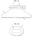
- FIG. 6 is a top view of a resonator having the shape of a modified stadium.
- FIGs 1, 5 and 6 have not been drawn to scale.
- the symbol A stands for Angstroms
- electric current it stands for Amperes.
- a solid state, micro-cylinder laser 10 in accordance with one aspect of our invention comprises a cylindrical body 12 disposed on a support or pedestal 14.
- An active region 12.1 is included within the body.
- the active region When suitably pumped, the active region generates stimulated emission of radiation (light) at a center wavelength determined by the bandgap of the active region material (e.g., in semiconductor diode lasers) or by quantum confinement characteristics of the structure (e.g., in semiconductor quantum cascade (QC) lasers).
- Illustrative semiconductors include Group III-V, Group II-VI and Group IV-VI compound materials.
- the active region material is not limited to semiconductors; it could comprise other relatively high refractive index, solid state materials.
- the laser 10 is depicted as having a pair of electrodes or contacts 16 (on body 12) and 18 (on pedestal 14) so that the active region can be pumped by means of an electric current supplied by a voltage source (not shown) connected across the electrodes.
- a voltage source not shown
- other forms of pumping well known in the art may also be utilized; e.g., optical pumping, in which case the electrodes could be omitted or made transparent to the pumping radiation.
- the active region is disposed between an upper cladding region 12.2, on which electrode 12.2 is formed, and a lower cladding region 12.3 disposed on the pedestal 14.
- the cladding regions generally have a lower refractive index than the active region and thereby serve to confine most of the energy of the lasing modes to the active region; i.e., the light intensity decreases exponentially in the cladding regions.
- the boundary of body 12, or at least the boundary of active region 12.1 forms a cylindrical cavity resonator which is sufficiently deformed from circularity, and the effective refractive index of the resonator is sufficiently high, so that the resonator supports at least one librational mode (e.g. a V-shaped mode or a bow-tie mode as shown in FIGs. 5C and 5D, respectively) and provides a directional output beam.
- librational mode e.g. a V-shaped mode or a bow-tie mode as shown in FIGs. 5C and 5D, respectively
- the body 12 includes a solid state waveguide that strongly confines the light to the body l2
- the effective refractive index would be essentially the average of the refractive indices of the layers making up the active and cladding regions (e.g., n ⁇ 3.5 for many Group III-V compound semiconductors).
- the body 12 contains no cladding layers and, therefore, the light penetrates significantly into air, then the effective refractive index would be lower. An illustration of the latter is found in C.
- a resonator with dipolar deformation could be particularly useful in supporting V-shaped modes.
- higher order deformations such as octapolar may also be useful.
- the curved boundary of the resonator be convex (i.e., at no point does the curvature of the relevant cross-section of the boundary change sign), but not precisely elliptical (the latter shape does not support librational modes).
- the curved boundary of the resonator may be convex (i.e., at no point does the curvature of the relevant cross-section of the boundary change sign), but not precisely elliptical (the latter shape does not support librational modes).
- the micro-cylinder laser 10 comprises a QC laser made of Group III-V compound semiconductors having a relatively high refractive index (i.e., n > 3.3) and the resonator is deformed from circularity approximately in accordance with the flattened quadrupolar equation (2).
- Deformation parameters ⁇ ⁇ 0.12, approximately, provide resonators which support librational modes, particularly bow-tie modes. Lasers operating in such modes have produced directional output beams at nearly 10 mW of optical power, more than three orders of magnitude greater than that of mid-infrared QC microdisk lasers having circular resonators.
- This example describes a Group III-V compound semiconductor, micro-cylinder, QC laser in accordance with one embodiment of our invention.
- Various materials, dimensions and operating conditions are provided by way of illustration only and, unless otherwise expressly stated, are not intended to limit the scope of the invention.
- the QC laser is particularly suited for two-dimensional micro-cylinder geometries. See, for example, J. Faist et al., Appl. Phys. Lett., Vol. 69, No.17, pp. 2456-2458 (1996), which is incorporated herein by reference, and C. Gmachl et al., supra..
- This type of laser is based on a transition between quantized conduction band states of a cascaded InGaAs/InAlAs coupled quantum-well structure (intersubband transition).
- intersubband transition the selection rule of the optical transition allows light emission only in the two-dimensional plane with polarization normal to the quantum well layers; i.e., transverse magnetic (TM) polarization.
- the QC laser is a unipolar device based on only electron transport, unlike diode lasers.
- the surface does not cause excess, unwanted non-radiative surface recombination of electrons and holes.
- the wavelength of operation e.g., 3.5-13 ⁇ m
- the material used is a well understood semiconductor system.
- MBE molecular beam epitaxy
- the effective refractive index of the body 12 i.e., active region together with the cladding regions
- the heterostructure was ultimately shaped into the form of disk 12 and the substrate into the form of pedestal 14.
- the InGaAs/InAlAs active region is well known in the art and is considered a mature and virtually optimized design for high quality laser performance. More specifically, the active region included 25 cascaded stages of so-called three-well vertical radiative transition regions with matching electron injection/relaxation regions. See, J. Faist et al, Appl. Phys. Lett., Vol. 68, No. 26, pp. 3680-3682 (1996) and J. Faist et al., IEEEJ. Quantum Electron, Vol. 34, No. 2, pp. 336-343 (1998), which are incorporated herein by reference.
- the cladding regions 12.2 and 12.3 each comprised three sublayers: (1) a low doped InGaAs layer (Si doped to 2 x 10 17 cm -3 and 350 nm thick) adjacent the active region, (2) an inner, low doped InAlAs layer (itself actually two sublayers: a first sub-layer Si doped to 2 x 10 17 cm -3 and 300 nm thick; and a second sub-layer Si doped to 3 x 10 17 cm -3 and 400 nm thick), and an outer, highly doped InAlAs layer (Si doped to 7 x 10 18 cm -3 and 1000 nm thick).
- a low doped InGaAs layer Si doped to 2 x 10 17 cm -3 and 350 nm thick
- an inner, low doped InAlAs layer itself actually two sublayers: a first sub-layer Si doped to 2 x 10 17 cm -3 and 300 nm thick; and a second sub-layer Si doped to 3
- a two-dimensional gas (2DEG) was formed by a highly doped, thin portion (Si doped to 5 x 10 18 cm -3 and 8 nm thick) of the InAlAs layer close to the interface.
- 2DEG two-dimensional gas
- the entire waveguide, formed by the active region and the two cladding regions, was designed to be symmetric and such that the lasing mode (the lowest order TM mode) had little ( ⁇ 0.5%) overlap with the InP substrate/pedestal. Thus, the possible detrimental effects of coupling light into the substrate were strongly reduced.
- the geometry of the resonator was realized by optical lithography and wet chemical etching.
- the approximate flattened quadrupolar shape was obtained by starting from a photoresist pattern that was composed of two semi-circles connected by a rectangle. The samples were then etched in an aged solution of 1:1:10 HBr:HNO 3 :H 2 O until deep mesas were obtained. Due to the smoothing action of the etchant the straight section of the etch mask bends towards the curved parts rendering a quadrupole-like shape of the disk 12, as shown in FIG. 1B.
- We controlled the photolithographic and etching processes so that we were able to fabricate lasers with deformation parameters ranging from 0 to about 0.2 in ten steps of 0.02 each. For all such lasers the height of the disk was about 5.4 ⁇ m (i.e., the total thickness of the MBE layers), whereas the lengths of its major and minor axes were varied as discussed below.
- Electrode 16 non-alloyed Ti/Au
- electrode 18 non-alloyed Ge/Au/Ag/Au
- the rim of the top electrode 16 had essentially the same distance from the edge of the disk 12 for all lasers (with the same length of the minor axis) and in all directions of ⁇ .
- the lasers were tested with their major axis oriented at 0°, 45° and 90° to the major orientation of the semiconductor crystal.
- the lasers were driven with current pulses (duration about 50 ns; repetition rate about 40 kHz) and the light output was measured using a cooled HgCdTe detector and a well known lock-in technique. To improve power output and avoid excess current heating the measurements were made at heat sink temperatures of 40° K-100° K. Nevertheless, the maximum pulsed operating temperature of the lasers was 270° K.
- the spectral properties were measured using a Fourier transform infrared (FTIR) spectrometer.
- FTIR Fourier transform infrared
- the lasers emitted light according to their symmetry into all quadrants of the two-dimensional laser plane.
- the small amount of light escaping vertical to the resonator plane results from diffraction and was measured integrated over the vertical extension.
- ⁇ 90° denotes the direction of the minor axis of the resonator
- FIG. 2 summarizes the results of the output power analysis.
- a striking result is the strong quasi-exponential) increase of the collected optical power with increasing deformation, as shown in the inset.
- the absolute power was also measured in some lasers with relatively high degrees of deformation.
- our lasers with deformed resonators also exhibit strong directionality, as demonstrated by the far-field measurements shown in FIG. 3A and FIG. 3C.
- lasers with circular cylindrical resonators display no directionality of their output emission.
- FIG. 3B shows the calculated intensity pattern (the modulus squared of the electric field) for a WG mode in a deformed resonator with ⁇ ⁇ 0.06.
- FIG. 3C shows the actual angle-resolved far-field pattern (one quadrant) of one laser having a circular resonator and two lasers having resonators with approximately flattened quadrupolar deformation.
- the general ray motion is highly chaotic in most of the phase-space. Therefore, the likely scenario for generating directional emission is for the lasing modes to be associated with the small regions of stable, regular motion which still remain, as seen in a Poincare surface of section (SOS), not shown.
- SOS Poincare surface of section
- the second region is in the vicinity of a stable four-bounce periodic orbit with the shape of a bow-tie (FIG. 5D).
- the calculated intensity pattern for this mode is shown in FIG 3D.
- the increased deformation also influences the spectral properties of the laser, which further confirms the existence of two different modal regimes manifested so clearly in the different types of far-field patterns.
- Characteristic spectra are shown in the insets to FIGs. 3A and 3C. At relatively low deformations the data exhibit a complex, dense modal spectrum, which we interpret as the lasing of several WG modes. In addition, the lasers were multi-mode starting from the lasing threshold, with close mode spacing, ⁇ ⁇ 15 nm, and show up to 10 almost equally strong modes at the maximum optical power.
- the multi-mode behavior (including the weak side modes depicted in FIG. 3C, left inset) of the more highly deformed resonators is consistent with the emission from bow-tie modes.
- the expected theoretical value was calculated assuming that adjacent modes differ by one wavelength along the modal path of the bow-tie. This calculation yielded a mode spacing of 39.5 nm, in excellent agreement with the experiment considering the uncertainty in the effective refractive index.
- the bow-tie modes can easily be distinguished from the transverse modes of the diametral curved mirror Fabry-Perot resonator along the minor axis (length L) of the resonator.
- bow-tie modes originate from a period-doubling bifurcation of the diametral modes, leading to approximately twice the optical path length.
- this example shows that semiconductor micro-cylinder lasers with a flattened quadrupolar resonators, sufficiently deformed to support bow-tie lasing modes, have substantially improved power output and directionality. In the favorable directions of the far-field power increases ofup to three orders of magnitude have been obtained.
- micro-cylinder is not so restricted and is intended to embrace cylindrical resonators with a wide variety of aspect ratios; i.e., those which have relatively small diameters and are relatively thin, as well those which have larger diameters and are thicker.
- our invention also embraces a micro-cylinder resonator which has the shape of a modified stadium shown in FIG.
- a resonator which includes a central section 20 having essentially parallel sides 20.1 and, on each end thereof, a circular section 22 which is not a full hemisphere (i.e., each circular section subtends an angle ⁇ which is less than 180°).
- the dimensions of the resonator are determined, as with other embodiments of our invention, by Poincare surface-of-section analysis to identify those configurations which support librational modes.
Landscapes
- Physics & Mathematics (AREA)
- Electromagnetism (AREA)
- Engineering & Computer Science (AREA)
- Plasma & Fusion (AREA)
- Optics & Photonics (AREA)
- Semiconductor Lasers (AREA)
- Lasers (AREA)
Applications Claiming Priority (2)
| Application Number | Priority Date | Filing Date | Title |
|---|---|---|---|
| US63577 | 1993-05-19 | ||
| US09/063,577 US6134257A (en) | 1998-04-21 | 1998-04-21 | Solid state laser for operation in librational modes |
Publications (3)
| Publication Number | Publication Date |
|---|---|
| EP0952641A2 true EP0952641A2 (fr) | 1999-10-27 |
| EP0952641A3 EP0952641A3 (fr) | 2003-04-16 |
| EP0952641B1 EP0952641B1 (fr) | 2005-09-14 |
Family
ID=22050137
Family Applications (1)
| Application Number | Title | Priority Date | Filing Date |
|---|---|---|---|
| EP99302856A Expired - Lifetime EP0952641B1 (fr) | 1998-04-21 | 1999-04-13 | Résonateur laser à l'état solide |
Country Status (4)
| Country | Link |
|---|---|
| US (2) | US6134257A (fr) |
| EP (1) | EP0952641B1 (fr) |
| JP (1) | JP3494918B2 (fr) |
| DE (1) | DE69927201T2 (fr) |
Cited By (1)
| Publication number | Priority date | Publication date | Assignee | Title |
|---|---|---|---|---|
| WO2002052653A1 (fr) * | 2000-12-25 | 2002-07-04 | Lev Vasilievich Kozhitov | Dispositifs semi-conducteurs non planaires munis d'une couche active close cylindrique |
Families Citing this family (45)
| Publication number | Priority date | Publication date | Assignee | Title |
|---|---|---|---|---|
| US6134257A (en) * | 1998-04-21 | 2000-10-17 | Lucent Technologies Inc. | Solid state laser for operation in librational modes |
| JP3658194B2 (ja) * | 1998-07-10 | 2005-06-08 | キヤノン株式会社 | リング共振器型レーザ |
| US6487232B1 (en) * | 1998-11-24 | 2002-11-26 | Agilent Technologies, Inc. | System and method for suppressing multimoding behavior of lasers |
| WO2001014929A1 (fr) * | 1999-08-23 | 2001-03-01 | The Arizona Board Of Regents Acting On Behalf Of The University Of Arizona | Dispositifs optoelectroniques integres hybrides |
| DE10108079A1 (de) * | 2000-05-30 | 2002-09-12 | Osram Opto Semiconductors Gmbh | Optisch gepumpte oberflächenemittierende Halbleiterlaservorrichtung und Verfahren zu deren Herstellung |
| US6483734B1 (en) | 2001-11-26 | 2002-11-19 | Hewlett Packard Company | Memory device having memory cells capable of four states |
| US7654140B2 (en) * | 2002-03-12 | 2010-02-02 | Cornell Research Foundation, Inc. | Heat pumped parametric MEMS device |
| US20040109692A1 (en) * | 2002-12-09 | 2004-06-10 | James Plante | FSO communication systems having high performance detectors |
| US7359418B2 (en) | 2003-02-13 | 2008-04-15 | Hamamatsu Photonics K.K. | Quantum cascade laser |
| JP4494721B2 (ja) * | 2003-02-13 | 2010-06-30 | 浜松ホトニクス株式会社 | 量子カスケードレーザ |
| US6882675B2 (en) * | 2003-04-15 | 2005-04-19 | Lucent Technologies Inc. | Optical resonators that include chaotic ray paths |
| US7535656B2 (en) | 2005-06-15 | 2009-05-19 | Daylight Solutions, Inc. | Lenses, optical sources, and their couplings |
| US7492806B2 (en) * | 2005-06-15 | 2009-02-17 | Daylight Solutions, Inc. | Compact mid-IR laser |
| US20100243891A1 (en) * | 2005-06-15 | 2010-09-30 | Timothy Day | Compact mid-ir laser |
| US7843283B2 (en) * | 2005-11-09 | 2010-11-30 | Cornell Research Foundation, Inc. | MEMS controlled oscillator |
| US7424042B2 (en) | 2006-09-22 | 2008-09-09 | Daylight Solutions, Inc. | Extended tuning in external cavity quantum cascade lasers |
| US7920608B2 (en) | 2007-03-12 | 2011-04-05 | Daylight Solutions, Inc. | Quantum cascade laser suitable for portable applications |
| US20090028197A1 (en) * | 2007-07-25 | 2009-01-29 | Daylight Solutions Inc | Fixed wavelength mid infrared laser source with an external cavity |
| US7668420B2 (en) * | 2007-07-26 | 2010-02-23 | Hewlett-Packard Development Company, L.P. | Optical waveguide ring resonator with an intracavity active element |
| US7848382B2 (en) * | 2008-01-17 | 2010-12-07 | Daylight Solutions, Inc. | Laser source that generates a plurality of alternative wavelength output beams |
| US8565275B2 (en) | 2008-04-29 | 2013-10-22 | Daylight Solutions, Inc. | Multi-wavelength high output laser source assembly with precision output beam |
| US9086375B2 (en) | 2008-04-29 | 2015-07-21 | Daylight Solutions, Inc. | Laser source with a large spectral range |
| FR2932616B1 (fr) * | 2008-06-13 | 2010-07-30 | Commissariat Energie Atomique | Dispositif laser d'emission d'onde terahertz |
| US8774244B2 (en) | 2009-04-21 | 2014-07-08 | Daylight Solutions, Inc. | Thermal pointer |
| RU2423764C1 (ru) * | 2009-12-07 | 2011-07-10 | Учреждение Российской академии наук Институт физики микроструктур РАН | Резонатор на модах шепчущей галереи с вертикальным выходом излучения |
| WO2011156033A2 (fr) | 2010-03-15 | 2011-12-15 | Daylight Solutions, Inc. | Source laser qui génère un faisceau de sortie changeant rapidement |
| US8335413B2 (en) | 2010-05-14 | 2012-12-18 | Daylight Solutions, Inc. | Optical switch |
| US8467430B2 (en) | 2010-09-23 | 2013-06-18 | Daylight Solutions, Inc. | Continuous wavelength tunable laser source with optimum orientation of grating and gain medium |
| US9225148B2 (en) | 2010-09-23 | 2015-12-29 | Daylight Solutions, Inc. | Laser source assembly with thermal control and mechanically stable mounting |
| US9042688B2 (en) | 2011-01-26 | 2015-05-26 | Daylight Solutions, Inc. | Multiple port, multiple state optical switch |
| US9059562B2 (en) | 2011-06-23 | 2015-06-16 | Daylight Solutions, Inc. | Control system for directing power to a laser assembly |
| US9093813B2 (en) | 2011-10-11 | 2015-07-28 | Daylight Solutions, Inc. | Mounting base for a laser system |
| US9496674B2 (en) | 2012-08-28 | 2016-11-15 | Daylight Solutions, Inc. | Rapidly tunable laser assembly |
| US9077137B2 (en) | 2013-03-08 | 2015-07-07 | Daylight Solutions, Inc. | Laser assembly with package beam pointing registration |
| US9147995B2 (en) | 2013-03-15 | 2015-09-29 | Daylight Solutions, Inc. | Rapidly tunable laser source assembly with long stroke grating mover |
| US9088126B2 (en) | 2013-10-17 | 2015-07-21 | The Trustees Of Princeton University | Single-mode quantum cascade lasers with enhanced tuning range |
| US10208902B2 (en) | 2013-10-23 | 2019-02-19 | Daylight Solutions, Inc. | Light source assembly with multiple, disparate light sources |
| US9791113B2 (en) | 2013-10-23 | 2017-10-17 | Daylight Solutions, Inc. | Light source assembly with multiple, disparate light sources |
| US11009217B2 (en) | 2013-10-23 | 2021-05-18 | Daylight Solutions, Inc. | Light source assembly with multiple, disparate light sources |
| RU2577787C2 (ru) | 2014-03-05 | 2016-03-20 | Юрий Георгиевич Шретер | Полупроводниковое светоизлучающее устройство с осью симметрии |
| DE102015108529A1 (de) | 2015-05-29 | 2016-12-01 | Osram Opto Semiconductors Gmbh | Halbleiterlaserdiode und Verfahren zur Herstellung einer Halbleiterlaserdiode |
| KR102384228B1 (ko) * | 2015-09-30 | 2022-04-07 | 삼성전자주식회사 | 반도체 레이저 공진기 및 이를 포함하는 반도체 레이저 소자 |
| KR102196386B1 (ko) * | 2019-07-10 | 2020-12-29 | 경북대학교 산학협력단 | 레이저 다이오드, 광 집적 소자, 및 이의 제조 방법 |
| JP7328656B2 (ja) * | 2020-05-11 | 2023-08-17 | 日本電信電話株式会社 | カオス振動発生装置 |
| CN114552349A (zh) * | 2020-11-24 | 2022-05-27 | 中国科学技术大学 | 椭圆柱形光学微谐振腔及椭圆柱形光学微谐振腔制备方法 |
Family Cites Families (6)
| Publication number | Priority date | Publication date | Assignee | Title |
|---|---|---|---|---|
| US4638485A (en) * | 1984-03-20 | 1987-01-20 | University Of Utah | Solid state vibrational lasers using F-center/molecular-defect pairs in alkali halides |
| US4829537A (en) * | 1986-12-01 | 1989-05-09 | Spectra-Physics, Inc. | Solid state lasers with spherical resonators |
| CA2068899C (fr) * | 1991-09-17 | 1997-06-17 | Samuel Leverte Mccall | Micro-resonateur a mode de chuchotement |
| US5351261A (en) * | 1993-04-14 | 1994-09-27 | At&T Bell Laboratories | Integrated optics |
| US5742633A (en) * | 1996-10-02 | 1998-04-21 | Yale University | Asymmetric resonant optical cavity apparatus |
| US6134257A (en) * | 1998-04-21 | 2000-10-17 | Lucent Technologies Inc. | Solid state laser for operation in librational modes |
-
1998
- 1998-04-21 US US09/063,577 patent/US6134257A/en not_active Expired - Lifetime
-
1999
- 1999-04-13 DE DE69927201T patent/DE69927201T2/de not_active Expired - Lifetime
- 1999-04-13 EP EP99302856A patent/EP0952641B1/fr not_active Expired - Lifetime
- 1999-04-20 JP JP11280899A patent/JP3494918B2/ja not_active Expired - Lifetime
-
2000
- 2000-06-12 US US09/591,716 patent/US6333944B1/en not_active Expired - Lifetime
Non-Patent Citations (6)
| Title |
|---|
| F. CAPASSO, C. GMACHL, D.L. SIVCO, A.Y. CHO, A.D. STONE, J. NOECKEL, E.E. NARIMANOV: "Semiconductor whispering gallery lasers with chaotic resonators" MAR98 MEETING OF THE AMERICAN PHYSICAL SOCIETY, [Online] 16 March 1998 (1998-03-16), XP001097249 Los Angeles Convention Center Retrieved from the Internet: <URL:http://www.aps.org/BAPSMAR98/abs/S104 0004.html> [retrieved on 2003-02-07] * |
| GMACHL C ET AL: "LONG-WAVELENGTH (9.5-11.5 MUM) MICRODISK QUANTUM-CASCADE LASERS" IEEE JOURNAL OF QUANTUM ELECTRONICS, IEEE INC. NEW YORK, US, vol. 33, no. 9, 1 September 1997 (1997-09-01), pages 1567-1572, XP000698860 ISSN: 0018-9197 * |
| J. N\CKEL, A. STONE, G. CHEN, H. GROSSMAN, R. CHANG: "Directional emission from asymmetric resonant cavities" OPTICS LETTERS, vol. 21, no. 19, 1 October 1996 (1996-10-01), pages 1609-1611, XP001121836 * |
| J.U. N\CKEL: "Classical phase space structure in optical microcavities" YEARBOOK OF MPI-PKS 1996-1997, April 1998 (1998-04), XP002230350 * |
| MAIR R A ET AL: "OPTICAL MODES WITHIN III-NITRIDE MULTIPLE QUANTUM WELL MICRODISK CAVITIES" APPLIED PHYSICS LETTERS, AMERICAN INSTITUTE OF PHYSICS. NEW YORK, US, vol. 72, no. 13, 30 March 1998 (1998-03-30), pages 1530-1532, XP000742885 ISSN: 0003-6951 * |
| N\CKEL J U ET AL: "RAY AND WAVE CHAOS IN ASYMMETRIC RESONANT OPTICAL CAVITIES" NATURE, MACMILLAN JOURNALS LTD. LONDON, GB, vol. 385, no. 6611, 2 January 1997 (1997-01-02), pages 45-47, XP001097502 ISSN: 0028-0836 * |
Cited By (1)
| Publication number | Priority date | Publication date | Assignee | Title |
|---|---|---|---|---|
| WO2002052653A1 (fr) * | 2000-12-25 | 2002-07-04 | Lev Vasilievich Kozhitov | Dispositifs semi-conducteurs non planaires munis d'une couche active close cylindrique |
Also Published As
| Publication number | Publication date |
|---|---|
| EP0952641B1 (fr) | 2005-09-14 |
| US6333944B1 (en) | 2001-12-25 |
| US6134257A (en) | 2000-10-17 |
| EP0952641A3 (fr) | 2003-04-16 |
| DE69927201D1 (de) | 2005-10-20 |
| JPH11330629A (ja) | 1999-11-30 |
| JP3494918B2 (ja) | 2004-02-09 |
| DE69927201T2 (de) | 2006-06-29 |
Similar Documents
| Publication | Publication Date | Title |
|---|---|---|
| EP0952641B1 (fr) | Résonateur laser à l'état solide | |
| Gerard et al. | Quantum boxes as active probes for photonic microstructures: The pillar microcavity case | |
| McCall et al. | Whispering‐gallery mode microdisk lasers | |
| Cao et al. | Optically pumped InAs quantum dot microdisk lasers | |
| AU750733B2 (en) | Narrow spectral width high power distributed feedback semiconductor lasers | |
| Gmachl et al. | Long-wavelength (9.5-11.5/spl mu/m) microdisk quantum-cascade lasers | |
| Mawst et al. | Resonant self‐aligned‐stripe antiguided diode laser array | |
| Gianordoli et al. | Long-wavelength (/spl lambda/= 10/spl mu/m) quadrupolar-shaped GaAs-AlGaAs microlasers | |
| Mawst et al. | Antiresonant reflecting optical waveguide‐type, single‐mode diode lasers | |
| Gourley et al. | High‐efficiency TEM continuous‐wave (Al, Ga) As epitaxial surface‐emitting lasers and effect of half‐wave periodic gain | |
| US20030189963A1 (en) | Low threshold microcavity light emitter | |
| US5539759A (en) | Single mode laser with a passive antiguide region | |
| Wenzel et al. | High-power diode lasers with small vertical beam divergence emitting at 808 nm | |
| US6370179B1 (en) | Low threshold microcavity light emitter | |
| Madhan Raj et al. | Multiple micro-cavity laser with benzocyclobutene/semiconductor high reflective mirrors fabricated by CH 4/H 2-reactive ion etching | |
| Shimokawa et al. | Continuous‐wave operation and mirror loss of a U‐shaped GaAs/AlGaAs laser diode with two totally reflecting mirrors | |
| Dikopoltsev et al. | Topological insulator VCSEL array | |
| US20160181470A1 (en) | High peak power quantum cascade superluminescent emitter | |
| Ou et al. | High‐power cw operation of InGaAs/GaAs surface‐emitting lasers with 45° intracavity micro‐mirrors | |
| Largent et al. | Fabrication of unstable resonator diode lasers | |
| Fang et al. | An InGaAs-GaAs strained layer single quantum-well ring laser with a reactive ion-etched tetragonal cavity | |
| Shinohara et al. | Long-path formation in a deformed microdisk laser | |
| Fang et al. | A corner reflector InGaAs-GaAs strained layer single quantum well coupled laser array | |
| Yap et al. | InGaAsP/InP buried‐heterostructure lasers with concurrent fabrication of the stripes and mirrors | |
| Mujagić et al. | Coherence and beam shaping in Quantum Cascade Lasers |
Legal Events
| Date | Code | Title | Description |
|---|---|---|---|
| PUAI | Public reference made under article 153(3) epc to a published international application that has entered the european phase |
Free format text: ORIGINAL CODE: 0009012 |
|
| AK | Designated contracting states |
Kind code of ref document: A2 Designated state(s): AT BE CH CY DE DK ES FI FR GB GR IE IT LI LU MC NL PT SE |
|
| AX | Request for extension of the european patent |
Free format text: AL;LT;LV;MK;RO;SI |
|
| RAP1 | Party data changed (applicant data changed or rights of an application transferred) |
Owner name: YALE UNIVERSITY Owner name: MAX-PLANCK-GESELLSCHAFT ZUR FOERDERUNG DER WISSEN Owner name: LUCENT TECHNOLOGIES INC. |
|
| PUAL | Search report despatched |
Free format text: ORIGINAL CODE: 0009013 |
|
| AK | Designated contracting states |
Designated state(s): AT BE CH CY DE DK ES FI FR GB GR IE IT LI LU MC NL PT SE |
|
| AX | Request for extension of the european patent |
Extension state: AL LT LV MK RO SI |
|
| 17P | Request for examination filed |
Effective date: 20031002 |
|
| 17Q | First examination report despatched |
Effective date: 20031104 |
|
| AKX | Designation fees paid |
Designated state(s): DE FR GB |
|
| GRAP | Despatch of communication of intention to grant a patent |
Free format text: ORIGINAL CODE: EPIDOSNIGR1 |
|
| GRAS | Grant fee paid |
Free format text: ORIGINAL CODE: EPIDOSNIGR3 |
|
| GRAA | (expected) grant |
Free format text: ORIGINAL CODE: 0009210 |
|
| AK | Designated contracting states |
Kind code of ref document: B1 Designated state(s): DE FR GB |
|
| REG | Reference to a national code |
Ref country code: GB Ref legal event code: FG4D |
|
| RIC1 | Information provided on ipc code assigned before grant |
Ipc: 7H 01S 5/30 B Ipc: 7H 01S 5/10 B Ipc: 7H 01S 3/06 A |
|
| REF | Corresponds to: |
Ref document number: 69927201 Country of ref document: DE Date of ref document: 20051020 Kind code of ref document: P |
|
| ET | Fr: translation filed | ||
| PLBE | No opposition filed within time limit |
Free format text: ORIGINAL CODE: 0009261 |
|
| STAA | Information on the status of an ep patent application or granted ep patent |
Free format text: STATUS: NO OPPOSITION FILED WITHIN TIME LIMIT |
|
| 26N | No opposition filed |
Effective date: 20060615 |
|
| REG | Reference to a national code |
Ref country code: FR Ref legal event code: CD Owner name: ALCATEL-LUCENT USA INC. Effective date: 20131122 |
|
| REG | Reference to a national code |
Ref country code: FR Ref legal event code: GC Effective date: 20140410 |
|
| REG | Reference to a national code |
Ref country code: FR Ref legal event code: RG Effective date: 20141015 |
|
| REG | Reference to a national code |
Ref country code: FR Ref legal event code: PLFP Year of fee payment: 18 |
|
| REG | Reference to a national code |
Ref country code: FR Ref legal event code: PLFP Year of fee payment: 19 |
|
| REG | Reference to a national code |
Ref country code: FR Ref legal event code: PLFP Year of fee payment: 20 |
|
| PGFP | Annual fee paid to national office [announced via postgrant information from national office to epo] |
Ref country code: DE Payment date: 20180420 Year of fee payment: 20 |
|
| PGFP | Annual fee paid to national office [announced via postgrant information from national office to epo] |
Ref country code: FR Payment date: 20180420 Year of fee payment: 20 |
|
| PGFP | Annual fee paid to national office [announced via postgrant information from national office to epo] |
Ref country code: GB Payment date: 20180418 Year of fee payment: 20 |
|
| REG | Reference to a national code |
Ref country code: DE Ref legal event code: R071 Ref document number: 69927201 Country of ref document: DE |
|
| REG | Reference to a national code |
Ref country code: GB Ref legal event code: PE20 Expiry date: 20190412 |
|
| PG25 | Lapsed in a contracting state [announced via postgrant information from national office to epo] |
Ref country code: GB Free format text: LAPSE BECAUSE OF EXPIRATION OF PROTECTION Effective date: 20190412 |