EP0952677A2 - Träger eines Mobilfunktelefons - Google Patents
Träger eines Mobilfunktelefons Download PDFInfo
- Publication number
- EP0952677A2 EP0952677A2 EP99302945A EP99302945A EP0952677A2 EP 0952677 A2 EP0952677 A2 EP 0952677A2 EP 99302945 A EP99302945 A EP 99302945A EP 99302945 A EP99302945 A EP 99302945A EP 0952677 A2 EP0952677 A2 EP 0952677A2
- Authority
- EP
- European Patent Office
- Prior art keywords
- carrier
- radiotelephone
- handstrap
- hanging
- user
- Prior art date
- Legal status (The legal status is an assumption and is not a legal conclusion. Google has not performed a legal analysis and makes no representation as to the accuracy of the status listed.)
- Withdrawn
Links
Images


Classifications
-
- H—ELECTRICITY
- H04—ELECTRIC COMMUNICATION TECHNIQUE
- H04B—TRANSMISSION
- H04B1/00—Details of transmission systems, not covered by a single one of groups H04B3/00 - H04B13/00; Details of transmission systems not characterised by the medium used for transmission
- H04B1/38—Transceivers, i.e. devices in which transmitter and receiver form a structural unit and in which at least one part is used for functions of transmitting and receiving
- H04B1/3827—Portable transceivers
- H04B1/3888—Arrangements for carrying or protecting transceivers
-
- A—HUMAN NECESSITIES
- A45—HAND OR TRAVELLING ARTICLES
- A45F—TRAVELLING OR CAMP EQUIPMENT: SACKS OR PACKS CARRIED ON THE BODY
- A45F5/00—Holders or carriers for hand articles; Holders or carriers for use while travelling or camping
-
- A—HUMAN NECESSITIES
- A45—HAND OR TRAVELLING ARTICLES
- A45F—TRAVELLING OR CAMP EQUIPMENT: SACKS OR PACKS CARRIED ON THE BODY
- A45F5/00—Holders or carriers for hand articles; Holders or carriers for use while travelling or camping
- A45F5/1516—Holders or carriers for portable handheld communication devices, e.g. pagers or smart phones
Definitions
- the present invention relates to a carrier for a radiotelephone.
- the present invention is concerned with enabling the user to conveniently carry a radiotelephone in different ways according to the situation.
- the present invention provides a carrier for a handportable radiotelephone comprising handstrap means connectable to first and second ends of a radiotelephone and hanging means by which the carrier is releasably hangable, in a handsfree manner, from the user's accoutrements.
- the carrier of the present invention can provide a suitable radiotelephone with dual mode support.
- a first hand-carry mode where the handstrap means provides auxiliary support to the telephone when the user holds the telephone in his hand in the normal way during a call.
- a second handsfree mode where the hanging means is attached to the user's accoutrements when the phone is in an on-hook condition, for example.
- the user's accoutrements may include the user's belt, belt loop, bag or the like.
- the hanging means includes a hanging assembly, which can be removed from the carrier.
- the hanging assembly may comprise a connector comprising a first portion connected to the handstrap means and a second portion connected to an accoutrement-connection means.
- the hanging means, or just the second portion of the connector and the accoutrement-connection means can be removed, whereby the carrier is reduced to a single mode configuration - with hand-carry capability only.
- the present invention may provide a radiotelephone comprising a housing having first and second carrier attachment means disposed at first and second ends of the housing and a carrier, the carrier comprising handstrap means connected to the first and second carrier attachment means and hanging means by which the radiotelephone is releasably hangable, in a handsfree manner, from the user's accoutrements.
- Figure 1 shows a cellular telephone which is generally designated 10.
- the internal components of the telephone 10 are located within housing 12 having a top end 12a, a bottom end 12b and sides 12c, 12d.
- a groove 13a is formed in the top end 12a.
- a groove 13b is formed in the bottom end 12b.
- the telephone 10 is provided with a keypad 14 and a display 16 as is conventional.
- the telephone 10 is provided with grips 18 on the sides.
- the grips 18 are made from a non-slip, soft elastomer and are ribbed. The grips 18 are bonded to the housing 12 and provide some measure of side-impact protection.
- the telephone 10 is also provided with metal mesh speaker and microphone covers 20,22 respectively.
- the mesh covers enable a relatively large opening to the exterior of the telephone to be used without making it more likely that foreign bodies will find their way inside the telephone and without any associated style penalty. Because relatively large openings to the audio transducers are possible, the position of the user to the telephone 10 when making a call is not so critical - this is particularly apparent with respect to the user's ear to speaker connection which benefits greatly from the greater speaker output catchment area.
- the telephone 10 also comprises first and second attachment loops 30, 40 mounted to the housing 12 in the region of the top end 12a and in the region of the bottom end 12b, respectively.
- Each attachment loop comprises a bar 32 from each end of which an arm 36,38 extends generally orthogonally therefrom to define a generally 'C' shape loop.
- the attachment loops 30,40 are mounted to the housing 12 by hinge mechanisms.
- this loop is attached to the housing 12 by a pair of hinge units 50a, 50b fixedly mounted within the housing, each hinge unit 50a, 50b being coupled to an arm of the second attachment loop 40.
- Figure 6 shows the hinge unit 50a enclosed by circle B and its connection to arm 36 in close-up detail. (The situation at the other hinge unit 50b is identical.)
- the end of the arm 36 is provided with an inwardly directed cup portion 37 which projects through an opening 42 in the housing 12.
- the cup portion 37 includes a recess 37a.
- the hinge unit 50a is fixedly mounted adjacent the opening 42 and includes a shaft 52 which mates with the recess 37a. Referring back to Figure 4, the hinge units 50a, 50b together permit the second attachment loop to be rotated about a fixed axis labelled FA.
- this loop is attached to the housing 12 by a pair of hinge units 50c, 50d, each hinge unit 50c, 50d being coupled to an arm of the first attachment loop 40.
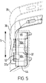
- Figure 5 shows the hinge unit 50c enclosed by circle A and its connection to arm 36 in close-up detail. (The situation at the other hinge unit 50d is identical.)
- the end of the arm 36 is provided with an inwardly directed cup portion 37 which projects through an opening 44 in the housing 12.
- the cup portion 37 includes a recess 37a.
- the hinge unit 50c includes a shaft 52 which mates with the recess 37a.
- the hinge unit 50c is mounted within a hinge carrier 46.
- the hinge carrier 46 sits in the opening 44 and permits the hinge unit 50c to slide back and forth within the carrier 46, as indicated by the double-headed arrow S. There is a tight fit between the hinge carrier 46 and the hinge unit 50c, such that the hinge unit 50c can be moved to any one of a number positions within the hinge carrier 46 by the user and will remain in that position in the absence of a force applied by the user. This is illustrated in Figures 4 and 6, where the two extreme positions which the hinge unit 50c (and hinge unit 50d) can adopt are illustrated simultaneously. In continuous lines, the hinge unit 50c is shown occupying its lowermost position within the hinge carrier 46, whereby the bar 32 (in continuous lines) rests in a retracted, idle position within the groove 13a.
- the hinge unit 50c is showing in its uppermost position within the hinge carrier 46, whereby the bar 32 (in dotted lines) stands proud from the top end 12a of the housing in an operational position. Since the hinge units 50c, 50d may be slid in this way, they together define a hinge mechanism having a movable hinge axis.
- the two extreme possible hinge axes, corresponding to the two illustrated positions of the hinge units 50c, 50d, are labeled MA1 and MA2 in Figure 4.
- Each hinge unit 50a-d is identical and is intemally constructed such that, at predetermined angular orientations, its shaft 42 occupies a favoured, rest position. Between these rest positions, the rotation of the shaft 42 is freewheeling. This is illustrated in Figure 7.
- the second attachment loop 40 is shown in three rest positions. Position P1, in continuous lines, and positions P2 and P3 in dotted lines. During rotation of the second attachment loop as indicated by the arrow R, if external forces applied by the user are removed when the attachment loop 40 is in any of positions P1, P2 or P3, it tends to remain at that position. On the other hand, if the attachment loop 40 is between rest positions P1, P2 or P3, it is free to converge under the weight of the attachment loop to one of the rest positions, where it remains.
- the second attachment loop has a rest position in which it sits in the groove 13b on the bottom side 12b of the housing 12 assuming an idle position.
- the bar 32 of each attachment loop 30, 40 is identical in construction.
- the length of the bar can be extended from its length in Figure 4 to a greater length permitting the withdrawal of the shafts 52 from their respective cup portions 37 and hence removal of the attachment loops 30, 40.
- the bar 32 comprises an outer tube 33 within which end portions 34 of the arms 36, 38 are slidably mounted.
- the end portions 34 include a short slot 34a within which a pin 33a formed on the outer tube 33 may travel.
- a spring 35 connecting the end portions 34 of the arms 36, 38 stiffly biases the attachment means into this position.
- the end portion 34 of the arm 38 can be drawn out telescopically from the tube 33, to an extent permitted by the engagement of the slot 34a and the pin 33a, thereby effectively increasing the length of the bar 32 withdrawing the shaft clear of the cup portion 37 enabling the attachment loop to be removed.
- the carrier 100 comprises a handstrap portion 105 comprising a strip of elastic material or webbing having a first end 107 and an opposite second end 109, and inner and outer faces 111 and 113, respectively.
- the inner face 111 is mainly visible.
- a further strap portion 115 projects dependently from the outer face 133 of the handstrap portion 105 from a region centrally located between the first and second ends 107,109.
- the strap portion 115 is inelastic and narrower in width than the handstrap 105. It is secured in position by being sandwiched between the handstrap portion 105 and a leather pad 121 which is stitched to the outer face thereof. Stitches pass through the strap portion 105 too.
- the leather pad can bear a logo or name, for example, that of the telephone manufacturer or service provider. No logo or name is shown in Figure 2.
- the inner and outer faces of the strap portion 115 are labelled 117 and 119, respectively.
- a first two-part velcro fastener comprises a first velcro fastener 123a on the outer face 111 of the handstrap portion 105 and a mating second velcro fastener 123b (shown in dotted outline in Figure 2) on the inner face 117 of the strap portion 105.
- a second two-part Velcro fastener comprises a first Velcro fastener 125a and a mating second Velcro fastener 125b positioned spaced apart from one another at the second end 109 of the handstrap portion 105.
- a protective tab 127 is provided on the outer face thereof. The Velcro fasteners 123,125 and the tab 127 are secured by stitching.
- the carrier 100 also comprises a hanging assembly 130.
- the hanging assembly comprises a two part plastic connector 132 and a belt-loop connector 148.
- the connector 132 comprises a base portion 134 and a disconnectable portion 144.
- the base portion 134 includes a male portion 136 for push-fit insertion into the disconnectable portion 144.
- the male portion includes a pair of wings 138a,138b which can be squeezed to towards one another to enable the two portions 134,144 of the connector to be separated.
- the base portion also includes a means by which the connector can be coupled to the strap portion 115.
- the means includes a shaft 140 which is loosely mounted to the framework of the base portion 134.
- the disconnectable portion 144 also includes a shaft (not visible in Figure 2) about which a belt connector 148 is attached.
- the belt connector 148 comprises a strip of inelastic material similar to the strap portion 105 having inner and outer faces 150, 152 respectively.
- the belt connector is folded around the shaft of the disconnectable portion of the connector 132 and secured in place by stitching. The free ends of the strip material are folded back on themselves and provided with a pair of conventional pop fasteners, one male fastener 156a and one female fastener 156b.
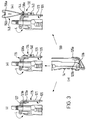
- FIG. 3 show the carrier 100 attached to the radiotelephone in various configurations. Because, in each configuration, the connection of the carrier 100 to the attachment loop 40 is the same, this is shown only once in Figure 3(iv).
- the carrier is attached via the second end 109 of the handstrap portion 105 to the attachment loop 40 by simply threading it through the attachment loop and looping it back around the bar, such that the bar is encircled, and fastening the parts of the second velcro fastener 125a, 125b together.
- the attachment loop 40 is shown extending vertically downwards. However, when the first end 107 of the handstrap portion 105 is attached to the attachment bar 30, as is about to be described variously, the tension in the handstrap portion 105, in practice, pulls the attachment bar into a position more like that shown in Figure 1.
- Figure 3(i) shows the first end 107 of the handstrap portion 105 connected to the attachment loop 30 when the hanging assembly 130 has been removed.
- the first end 107 of the handstrap portion 105 and the strap portion 115 are together passed over the bar 32 and together threaded back through the attachment loop 30, as illustrated by the arrow L, to enable the parts of the first velcro fastener 123a, 123b to join together, i.e. enabling the fastener 123b on the end of the strap portion 115 to join with the fastener 123a on the handstrap portion 105.
- the pad 127 on the first end 107 of the handstrap portion may or may not be partially sandwiched between the first Velcro fasteners 123a,123b.
- Figure 3(ii) shows the first end 107 of the handstrap portion 105 connected to the attachment loop 30 when the base portion 134 of the connector 132 is fitted.
- connection process is the same except there is the further initial step of the base portion 134 of the connector 132 being threaded onto the strap portion 115.
- Figure 3(iii) shows connection the first end 107 of the handstrap portion 105 to attachment loop 30 when the whole hanging assembly 130 has been fitted. This differs from Figure 3(ii) only in that the second portion 144 of the connector has been connected to the first base portion 134.
- the user will be able to use the carrier 100 in the hand-carry mode, in which mode the user is able to hold the telephone 10 in his palm in the normal way with his fingers passing between the handstrap portion 105 and the back of the telephone.
- the handstrap portion 105 serves to urge the telephone 10 into the palm of the user.
- the strap 100 serves to retain the telephone in contact with the hand, thereby providing auxiliary support for the telephone.
- the belt connector 148 is clipped around a belt (not shown) such that the belt is confined in the region labelled X in Figure 3(iii).
- the user wishes to make call, he has two choices. He can unclip the belt connector by unpopping the fasteners 156a and 156b or, he can squeeze the wings 138a and 138b together and disconnect the second portion of the connector 144 from the base portion 134 bringing the carrier into its Figure 3(ii) condition.
- the latter approach has the advantage that the telephone 10 can very rapidly restored to the handsfree carry mode after the call has been made.
- Figure 8 shows an alternative accoutrement-connection means showing a conventional connector suitable for connection to a belt-loop or a loop found on a bag or the like.
- the member 160 is biased into the position in Figure 8 but can by the application of a an inwardly directed force indicated by the arrow D, pivot the member 160 in a clockwise direction from the Figure 8 view to enable connection/disconnection.
- the carrier of the present invention enables the user to carry the radiotelephone 10 in a number of different ways according to the situation and to his needs or preferences.
- the user can remove the strap 100 altogether. The user may then choose to fit another strap.
- either (or even both) attachment loop 30, 40 is not required it can either be removed completely or withdrawn into its idle position (i.e. in the idle position, for the attachment loop 30, the bar 32 sits in the groove 13a and for the attachment loop 40, the bar 32 sits in the groove 13b) so as not to interfere with the user's normal use of the telephone.
- the user does not take the trouble to move the attachment loops into their respective idle positions, they are not prone to rattling caused by rotational movement because of the favoured, rest positions of the hinge units 50a-d, as previously described.
- the first attachment loop is not prone to rattling because of the linear displacement of the hinge units 50c, 50d because of the tight frictional fit between the hinge units 50c ,50d and the hinge carrier 46.
- the hinge units may simply be spring biased to a single predetermined position to avoid rattling.
Landscapes
- Engineering & Computer Science (AREA)
- Computer Networks & Wireless Communication (AREA)
- Signal Processing (AREA)
- Telephone Set Structure (AREA)
- Purses, Travelling Bags, Baskets, Or Suitcases (AREA)
Applications Claiming Priority (4)
| Application Number | Priority Date | Filing Date | Title |
|---|---|---|---|
| GB9808021A GB2336500B (en) | 1998-04-16 | 1998-04-16 | Radiotelephone |
| GB9808021 | 1998-04-16 | ||
| GB9822577A GB2339359B (en) | 1998-04-16 | 1998-10-16 | Carrier for a radio telephone |
| GB9822577 | 1998-10-16 |
Publications (2)
| Publication Number | Publication Date |
|---|---|
| EP0952677A2 true EP0952677A2 (de) | 1999-10-27 |
| EP0952677A3 EP0952677A3 (de) | 2003-04-16 |
Family
ID=26313478
Family Applications (1)
| Application Number | Title | Priority Date | Filing Date |
|---|---|---|---|
| EP99302945A Withdrawn EP0952677A3 (de) | 1998-04-16 | 1999-04-16 | Träger eines Mobilfunktelefons |
Country Status (4)
| Country | Link |
|---|---|
| US (1) | US6603856B1 (de) |
| EP (1) | EP0952677A3 (de) |
| JP (1) | JP2000036860A (de) |
| CN (1) | CN1197326C (de) |
Families Citing this family (4)
| Publication number | Priority date | Publication date | Assignee | Title |
|---|---|---|---|---|
| AU2003247348A1 (en) * | 2002-04-23 | 2003-11-10 | Digithong, Inc. | Cellular telephone and pda carrying system |
| US20040096079A1 (en) * | 2002-11-19 | 2004-05-20 | Wang Wang Dah Enterprise Co., Ltd. | Fastening device for earphone |
| US10085545B2 (en) * | 2015-10-20 | 2018-10-02 | Motorola Solutions, Inc. | Stabilized shoulder mount for electronic device |
| US20180177284A1 (en) * | 2016-12-27 | 2018-06-28 | Black Rapid, Inc. | Phone carrier |
Citations (1)
| Publication number | Priority date | Publication date | Assignee | Title |
|---|---|---|---|---|
| JPH09298370A (ja) * | 1996-05-08 | 1997-11-18 | Nec Corp | 携帯機器用ハンドストラップ |
Family Cites Families (10)
| Publication number | Priority date | Publication date | Assignee | Title |
|---|---|---|---|---|
| US2439410A (en) * | 1942-02-20 | 1948-04-13 | Motorola Inc | Combined radio transmitter and receiver |
| US3495770A (en) * | 1967-11-01 | 1970-02-17 | Robert H Seltmann Jr | Weapon sling |
| US4416405A (en) * | 1982-07-19 | 1983-11-22 | Caillouet Jerome P | Camera body tie down and quick release device |
| JPH01265750A (ja) * | 1988-04-18 | 1989-10-23 | Matsushita Electric Ind Co Ltd | 小型携帯電話機の背面ベルト装置 |
| FI90614C (fi) * | 1992-04-27 | 1994-03-10 | Nokia Mobile Phones Ltd | Rannelenkki |
| JP3255995B2 (ja) * | 1992-10-23 | 2002-02-12 | 株式会社日立製作所 | テレビ電話装置 |
| IT233685Y1 (it) | 1994-07-20 | 2000-02-03 | Stefano Uno S R L | Custodia porta-telefono del tipo portatile specialmente per borse a tracolla. |
| US5535928A (en) | 1995-03-13 | 1996-07-16 | Vel-Tye, L.L.C. | Belt-supportable carrier for portable articles |
| JP2677246B2 (ja) * | 1995-05-24 | 1997-11-17 | 日本電気株式会社 | 携帯用電話機 |
| IT235923Y1 (it) | 1995-08-10 | 2000-07-18 | Bugane Primo | Porta-custodia da cintola per telefono cellulare |
-
1999
- 1999-04-15 CN CNB991075374A patent/CN1197326C/zh not_active Expired - Fee Related
- 1999-04-15 JP JP11107348A patent/JP2000036860A/ja not_active Withdrawn
- 1999-04-16 EP EP99302945A patent/EP0952677A3/de not_active Withdrawn
- 1999-04-16 US US09/292,963 patent/US6603856B1/en not_active Expired - Lifetime
Patent Citations (1)
| Publication number | Priority date | Publication date | Assignee | Title |
|---|---|---|---|---|
| JPH09298370A (ja) * | 1996-05-08 | 1997-11-18 | Nec Corp | 携帯機器用ハンドストラップ |
Non-Patent Citations (1)
| Title |
|---|
| PATENT ABSTRACTS OF JAPAN * |
Also Published As
| Publication number | Publication date |
|---|---|
| US6603856B1 (en) | 2003-08-05 |
| CN1197326C (zh) | 2005-04-13 |
| JP2000036860A (ja) | 2000-02-02 |
| CN1241082A (zh) | 2000-01-12 |
| EP0952677A3 (de) | 2003-04-16 |
Similar Documents
| Publication | Publication Date | Title |
|---|---|---|
| EP1161358B1 (de) | Etui für ein mobiles endgerät | |
| US20030164389A1 (en) | Device for carrying articles on the wrist | |
| US7508932B1 (en) | Cell phone holder headband | |
| GB2339359A (en) | Hand strap carrier for a radiotelephone. | |
| JPH11155625A (ja) | 携帯装置のハンドストラップとこのハンドストラップの取付構造 | |
| EP0952677A2 (de) | Träger eines Mobilfunktelefons | |
| JP2003013317A (ja) | 電子機器用衣服 | |
| KR200342564Y1 (ko) | 버클폰 | |
| JP2002344590A (ja) | 携帯電話用リストホルダー | |
| KR20050117259A (ko) | 휴대 기기용 스트랩 끼움 보조 도구 | |
| KR200378096Y1 (ko) | 손등 부착용 휴대폰 홀더 | |
| JP3142789B2 (ja) | 携帯端末ホルダ | |
| CN223855262U (zh) | 低成本防勒手电子产品支撑结构 | |
| CN223194745U (zh) | 一种便携式手机夹具 | |
| WO2003045187A1 (en) | Means for attaching a lanyard to a handheld communication device | |
| KR200387238Y1 (ko) | 차량의 안전벨트에 장착되는 휴대용 단말기 케이스 | |
| JP2002051134A (ja) | 携帯電話機用収納ケース | |
| JP2006086564A (ja) | 携帯通信装置 | |
| CN210749693U (zh) | 一种矫正带 | |
| JP2001340136A (ja) | リュックサック | |
| JP3063424U (ja) | 時計バンド | |
| KR200256221Y1 (ko) | 멜빵과 탈착이 용이한 주머니 세트 | |
| US20040005050A1 (en) | Hands free personal phone holder | |
| JP3054538U (ja) | 携帯電話機用保持具および携帯電話機 | |
| JP3034011U (ja) | 移動電話用収納ケース |
Legal Events
| Date | Code | Title | Description |
|---|---|---|---|
| PUAI | Public reference made under article 153(3) epc to a published international application that has entered the european phase |
Free format text: ORIGINAL CODE: 0009012 |
|
| AK | Designated contracting states |
Kind code of ref document: A2 Designated state(s): AT BE CH CY DE DK ES FI FR GB GR IE IT LI LU MC NL PT SE |
|
| AX | Request for extension of the european patent |
Free format text: AL;LT;LV;MK;RO;SI |
|
| RAP1 | Party data changed (applicant data changed or rights of an application transferred) |
Owner name: NOKIA CORPORATION |
|
| PUAL | Search report despatched |
Free format text: ORIGINAL CODE: 0009013 |
|
| AK | Designated contracting states |
Designated state(s): AT BE CH CY DE DK ES FI FR GB GR IE IT LI LU MC NL PT SE |
|
| AX | Request for extension of the european patent |
Extension state: AL LT LV MK RO SI |
|
| RIC1 | Information provided on ipc code assigned before grant |
Ipc: 7A 45F 5/02 B Ipc: 7H 04M 1/04 B Ipc: 7H 04B 1/38 A |
|
| 17P | Request for examination filed |
Effective date: 20031016 |
|
| AKX | Designation fees paid |
Designated state(s): DE FR IT NL |
|
| 17Q | First examination report despatched |
Effective date: 20040119 |
|
| GRAP | Despatch of communication of intention to grant a patent |
Free format text: ORIGINAL CODE: EPIDOSNIGR1 |
|
| GRAC | Information related to communication of intention to grant a patent modified |
Free format text: ORIGINAL CODE: EPIDOSCIGR1 |
|
| GRAS | Grant fee paid |
Free format text: ORIGINAL CODE: EPIDOSNIGR3 |
|
| STAA | Information on the status of an ep patent application or granted ep patent |
Free format text: STATUS: THE APPLICATION IS DEEMED TO BE WITHDRAWN |
|
| 18D | Application deemed to be withdrawn |
Effective date: 20060113 |