EP0952730A2 - Dispositif à l'état solide de prise de vue et méthode pour son opération - Google Patents
Dispositif à l'état solide de prise de vue et méthode pour son opération Download PDFInfo
- Publication number
- EP0952730A2 EP0952730A2 EP99303078A EP99303078A EP0952730A2 EP 0952730 A2 EP0952730 A2 EP 0952730A2 EP 99303078 A EP99303078 A EP 99303078A EP 99303078 A EP99303078 A EP 99303078A EP 0952730 A2 EP0952730 A2 EP 0952730A2
- Authority
- EP
- European Patent Office
- Prior art keywords
- field effect
- effect transistor
- gate
- solid
- image sensing
- Prior art date
- Legal status (The legal status is an assumption and is not a legal conclusion. Google has not performed a legal analysis and makes no representation as to the accuracy of the status listed.)
- Granted
Links
Images









Classifications
-
- H—ELECTRICITY
- H04—ELECTRIC COMMUNICATION TECHNIQUE
- H04N—PICTORIAL COMMUNICATION, e.g. TELEVISION
- H04N25/00—Circuitry of solid-state image sensors [SSIS]; Control thereof
- H04N25/60—Noise processing, e.g. detecting, correcting, reducing or removing noise
- H04N25/67—Noise processing, e.g. detecting, correcting, reducing or removing noise applied to fixed-pattern noise, e.g. non-uniformity of response
- H04N25/671—Noise processing, e.g. detecting, correcting, reducing or removing noise applied to fixed-pattern noise, e.g. non-uniformity of response for non-uniformity detection or correction
- H04N25/677—Noise processing, e.g. detecting, correcting, reducing or removing noise applied to fixed-pattern noise, e.g. non-uniformity of response for non-uniformity detection or correction for reducing the column or line fixed pattern noise
-
- H—ELECTRICITY
- H04—ELECTRIC COMMUNICATION TECHNIQUE
- H04N—PICTORIAL COMMUNICATION, e.g. TELEVISION
- H04N25/00—Circuitry of solid-state image sensors [SSIS]; Control thereof
- H04N25/70—SSIS architectures; Circuits associated therewith
- H04N25/76—Addressed sensors, e.g. MOS or CMOS sensors
- H04N25/77—Pixel circuitry, e.g. memories, A/D converters, pixel amplifiers, shared circuits or shared components
-
- H—ELECTRICITY
- H04—ELECTRIC COMMUNICATION TECHNIQUE
- H04N—PICTORIAL COMMUNICATION, e.g. TELEVISION
- H04N25/00—Circuitry of solid-state image sensors [SSIS]; Control thereof
- H04N25/70—SSIS architectures; Circuits associated therewith
- H04N25/76—Addressed sensors, e.g. MOS or CMOS sensors
- H04N25/78—Readout circuits for addressed sensors, e.g. output amplifiers or A/D converters
Definitions
- the present invention relates to a solid-state image sensing apparatus and a method of operating the same and, more particularly, to a solid-state image sensing apparatus widely used in an image input apparatus, such as a video camera and a digital still camera, and a method of driving the solid-state image sensing apparatus.
- MOS-type photoelectric conversion apparatuses there are metal oxide semiconductor (MOS) type, an amplified MOS imager (AMI), a charge modulation device (CMD), and a base stored image sensor (BASIS), for instance, but not a conventional charge-coupled device (CCD) type.
- MOS-type photoelectric conversion apparatus photo-electrons generated by a photodiode, as a photoelectric conversion element, are collected at the gate of a MOS transistor, and the charge at the gate is amplified using a change in potential at the gate caused by the charge and outputted to an output unit in accordance with a driving signal from an operation circuit.
- CMOS complementary MOS
- peripheral circuits can be integrally formed on the same chip easily.
- the CMOS-type photoelectric conversion apparatus can be operated with a low voltage, which saves electrical energy; therefore, it is anticipated as a useful image sensor for a portable device. Since photodiodes, i.e., photoelectric conversion elements, of the CMOS-type image sensor and their peripheral circuits are made in the CMOS logic LSI processing, the photodiodes and the peripheral circuits are collectively called a CMOS image sensor.
- the CMOS image sensor has one or more MOS field effect transistors (FETs) in each cell (pixel).
- FETs MOS field effect transistors
- MOS amplifier MOS amplifier
- the output signal level is increased by amplifying photo-charge using the MOS amplifier provided in each pixel; however, at the same time, irregularity in threshold voltages Vth and gain of the MOS amplifier causes deterioration of the S/N ratio. Especially, it is not possible to restrain irregularity in the threshold voltages Vth below several millivolts under the current manufacturing technique. Further, the saturation voltage of the MOS amplifier is in some volts range since the saturation voltage depends upon the voltage of the power supply. Therefore, the S/N ratio is a three-digit number at best, and it is very difficult to achieve 70 to 80dB, which is the demand of the market.
- a read circuit using a capacitive clamp circuit as shown in Fig. 17, is disclosed in the Japanese Patent Application Laid-Open No. 4-61573.
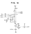
- Fig. 18 shows an equivalent circuit of a pixel of a solid state image sensing apparatus disclosed in the above reference. Below, the operation of the image sensing apparatus is briefly explained with reference to the equivalent circuit of a pixel shown in Fig. 18 and the timing chart shown in Fig. 19.
- signals ⁇ CR1, ⁇ CR2 and ⁇ CS1 at time t 31p are changed to high, thereby a MOS switch Q16 is turned on; in turn, a vertical signal line VL3 becomes a ground level, and capacitors C1 and C3 are reset to a voltage VSS.
- a signal ⁇ CR1 is changed to a low level at time t 32p , further, a reset signal ⁇ RS is changed to a high level, thereby the gate of the MOS amplifier Q2 is reset to a voltage VRS.
- the reset signal ⁇ RS is changed to a low level and a signal ⁇ V3 is changed to high, thereby a MOS FET Q3 for selection (referred to as "MOS selector” hereinafter) is turned on, and an operation voltage VDD is provided to the drain of the MOS amplifier Q2. Accordingly, a voltage VN corresponding to the gate voltage of the MOS amplifier Q2 appears on the vertical signal line VL3 (noise signal).
- the signal ⁇ CR2 is changed to low at time t 34p , which puts the output side of the capacitor C1 and one electrode of the capacitor C3 in a floating state.
- the signal ⁇ V3 is changed to low to turn the MOS selector Q3 off.
- the signal ⁇ CR1 is changed to high to reset the vertical signal line VL3, thereby the potential of the output side of the capacitor C1 and one electrode of the capacitor C3 becomes a potential, VSS - VN', that is the bias voltage VSS is reduced by a voltage VN', which is a part of the voltage VN, corresponding to the ratio of the capacitance of the capacitor C1 to the total capacitance of the capacitors C1 and C3.
- VN' is expressed by the following equation (1).
- VN' C1 ⁇ VN/(C1 + C3)
- the signal ⁇ CR1 is changed to low
- the signal ⁇ V3, applied to the gate of the MOS selector Q3, and a signal ⁇ VG, applied to the gate of a MOS FET Ql for transferring photo-charge (referred to as "MOS switch” hereinafter), are changed to high. Accordingly, the MOS switch Ql is turned on, and the photo-charge generated by the photodiode D1 is transferred to an input capacitor CP.
- the MOS selector Q3 is turned on, and the operation voltage VDD is provided to the drain of the MOS amplifier Q2 via the MOS selector Q3, thereby a voltage VS, corresponding to the gate voltage of the MOS amplifier Q2 appears on the vertical signal line VL3 (photo-charge signal).
- a voltage across the capacitor C1 is increased by a voltage VS', which is a part of the voltage VS, corresponding to the ratio of the capacitance of the capacitor C1 to the total capacitance of the capacitors C1 and C3, and becomes VSS - VN' + VS'.
- the voltage VS' is expressed by the following equation (2), similarly to the voltage VN'.
- VS' C1 ⁇ VS/(C1 + C3)
- a capacitance of a capacitor C which is connected to the gate of the FET affects the maximum charge capable of being transferred, namely, the maximum allowable charge Qsat, when transferring photo-charge generated by the photoelectric conversion element to the gate of the FET.
- the capacitor C3 needs to have capacitance of several pF.
- the capacitor C1 when reading photo-charge from each pixel, which is determined by a part of the second term of equation (3), namely C1/(C1 + C3), the capacitor C1 needs to have a capacitance of least several times larger than the capacitance of the capacitor C3.
- satisfactory sensitivity can not always be obtained.
- the voltage for resetting the vertical signal line VL3 must be sufficient to turn on the MOS amplifier Q2 for every signal level inputted to the gate of the MOS amplifier Q2, thus restricts the reset voltage.
- the concept of resetting the vertical signal line VL3 is disclosed in, e.g., the Japanese Patent Application Laid-Open No. 5848577 and the Japanese Patent Publication No. 5-18309 for preventing interference between pixels, such as leakage of charge, in a photoelectric conversion element having non-destructive reading characteristics.
- a signal ⁇ P V1 becomes high, and MOS switches S 1 1 to S 768 1 which are connected to a vertical signal line V1 of a sensor array C J i are turned on, thereby photo-charges in cells (pixels) C 1 1 to C 768 1 are outputted to signal output lines B1 to B768.
- MOS switches Q 1 1 to Q 1 32 in a horizontal switch circuit are turned on, thereby photo-charge on the left-most signal output line in each of the 32 sub-groups, each includes 24 signal output lines, of the signal output lines B1 to B768 is outputted to multiplexing output lines A1 to A32. Signals on the multiplexing output lines A1 to A32 are outputted through amplifiers T1 to T32, respectively.
- Each of the amplifiers T1 to T32 comprises a pair of differential transistors both connected between a common constant current source and ground.
- an analog pixel (photo-charge) signal is inputted, whereas to the base of the other transistor, a dark voltage from a pixel which is shielded from light is inputted. Then an analog signal obtained by subtracting the dark voltage from the analog pixel signal is outputted.
- the signal ⁇ P H1 applied to the horizontal signal line H1 becomes low, and a signal ⁇ P H2 on a horizontal signal line H2 becomes high at time t 2p .
- the MOS switches Q 2 1 to Q 2 32 in a horizontal switch circuit are turned on, thereby pixel signals on signal output lines which are the second to the left-most lines in the respective 32 sub-groups of signal output lines B1 to B768 are outputted to multiplexing output lines A1 to A32.
- signals to be applied to the horizontal signal lines H3 to H24 sequentially become high, and analog pixel signals of the respective sub-groups are outputted.
- the signal ⁇ P H24 applied to the last horizontal signal line H24 becomes low, the signal ⁇ P V1 applied to the vertical signal line V1 becomes low, thereby scanning of all the cells connected to the signal line V1 is completed.
- a blanking period elapses.
- signals ⁇ P H1 to ⁇ P H24 applied to the horizontal signal lines H1 to H24 are turned to high, thereby connecting all the signal output lines B1 to B768 to the corresponding output lines A1 to A32.
- a signal ⁇ P R on a refresh line R is turned to high and MOS switches R1 to R32 are turned on, thereby the multiplexing output lines Al to A32 are grounded. Accordingly, all the signal output lines B1 to B768 are grounded, and residues of pixel signals remaining from the previous scanning are cleared.
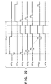
- Fig. 23 shows a case of reading pixel signals from the cells connected to the vertical signal line V1.
- a signal voltage of the cell C 1 1 is denoted by VS1
- signal voltages of the cells C 2 1 to C 24 1 are denoted by VS2 to VS24, respectively.
- parasitic capacitance of the signal output lines B1 to B24 is denoted by C11
- parasitic capacitance connected to the base of the transistor connected to the differential transistor T1 is denoted by C21
- the common signal output line is A1
- VSO a signal voltage inputted to the base of the transistor
- VSO (C21 ⁇ VSO' + C11 ⁇ VS2) / (C21 + C11)
- the present invention has been made in consideration of the above situation, and has as its object to improve the S/N ratio and widen the dynamic range of image signals obtained from a solid-state image sensing apparatus.
- the foregoing object is attained by providing a method of operating a solid-state image sensing apparatus having pixels each including a photoelectric conversion element, a field effect transistor whose gate receives photo-charge generated by the photoelectric conversion element, and a transfer switch for controlling connection between the photoelectric conversion element and the gate of the field effect transistor, wherein transference of the photo-charge from the photoelectric conversion element to the gate of the field effect transistor is performed under a condition that a channel is formed under the gate of the field effect transistor.
- the foregoing object is also attained by providing a method of operating a solid-state image sensing apparatus having pixels each including a photoelectric conversion element, a field effect transistor whose gate receives photo-charge generated by the photoelectric conversion element, a first switch for controlling connection between the photoelectric conversion element and the gate of the field effect transistor, and a first reset means for resetting the gate of the field effect transistor, and output lines for transferring an output from the field effect transistors, load means, provided on the output lines, for the field effect transistors, and second reset means for resetting the output lines to a predetermined voltage, wherein the output lines are reset by the second reset means in advance of connecting of the photoelectric conversion element and the gate of the field effect transistor.
- a solid-state image sensing apparatus having pixels each including a photoelectric conversion element, a field effect transistor whose gate receives photo-charge generated by the photoelectric conversion element, and a transfer switch for controlling connection between the photoelectric conversion element and the gate of the field effect transistor, comprising control means for controlling that transference of the photo-charge from the photoelectric conversion element to the gate of the field effect transistor is performed under a condition that a channel is formed under the gate of the field effect transistor.
- a solid-state image sensing apparatus having pixels each including a photoelectric conversion element, a field effect transistor whose gate receives photo-charge generated by the photoelectric conversion element, a first switch for controlling connection between the photoelectric conversion element and the gate of the field effect transistor, and a first reset means for resetting the gate of the field effect transistor, and output lines for transferring an output from the field effect transistors, comprising load means, provided on the output lines, for the field effect transistors; and second reset means for resetting the output lines to a predetermined voltage.
- the solid-state image sensing apparatus provides photo-charge, generated by the photodiode D1 in accordance with the quantity of light, to the MOS amplifier Q2 via the MOS switch Q1, then turns on the MOS selector Q3 to transfer the photo-charge to a vertical signal line VL3.
- the signals ⁇ CR1, ⁇ CR2 and ⁇ CS1 at time t 1 are changed to high, thereby a MOS switch Q16 is turned on; in turn, the vertical signal line VL3 becomes a ground level, and the capacitors C1 and C3 are reset to the voltage VSS.
- the signal ⁇ CR1 is changed to a low level at time t 2 , further, the reset signal ⁇ RS is changed to a high level, thereby the gate of the MOS amplifier Q2 is reset to the voltage VRS.
- the reset signal ⁇ RS is changed to a low level and the signal ⁇ V3 is changed to high, thereby the MOS selector Q3 is turned on, and the operation voltage VDD is provided to the drain of the MOS amplifier Q2. Accordingly, a voltage VN corresponding to the gate voltage of the MOS amplifier Q2 appears on the vertical signal line VL3 (noise signal).
- the signal ⁇ CR2 is changed to low at time t 4 , which puts the output side of the capacitor C1 and one electrode of the capacitor C3 in a floating state.
- the signal ⁇ V3 is changed to low to turn the MOS selector Q3 off.
- the signal ⁇ CR1 is changed to high to reset the vertical signal line VL3, thereby the potential of the output side of the capacitor C1 and one electrode of the capacitor C3 becomes a potential, VSS - VN', that is, the bias voltage VSS is reduced by a voltage VN', which is a part of the voltage VN, corresponding to the ratio of the capacitance of the capacitor C1 to the total capacitance of the capacitors C1 and C3.
- the signal ⁇ VG applied to the gate of the MOS switch Q1 is changed to high, and photo-charge is transferred from the photodiode D1 to the gate of the MOS amplifier Q2.
- the signal ⁇ CR1 is kept high to fix the source of the MOS amplifier Q2 to a ground level, and the signal ⁇ V3 is set to low to cut the supply of the voltage VDD to the drain of the MOS amplifier Q2, thereby it is possible to restrain the operational range of the MOS amplifier Q2 to the triode region.
- a potential at the drain of the MOS amplifier Q2 decreases to near the ground level, thereby a bias relationship between the gate and the drain of the MOS amplifier Q2, namely a potential difference between the gate and the drain of the MOS amplifier Q2 is greater than a threshold, is maintained.
- the signal ⁇ VG is changed to low at time t 6 , then, the signal ⁇ CR1 is changed to low and the signal ⁇ V3 is changed to high at time t 7 , a voltage VS corresponding to the photo-charge transferred to the gate of the MOS amplifier Q2 appears on the vertical signal line VL3 (photo-charge signal). Accordingly, the potential at the output side of the capacitor C1 and one electrode of the capacitor C3 becomes (VSS - VN' + VS').
- transference of a photo-charge signal from a photodiode of a photoelectric conversion element to the gate of a field effect transistor (FET) which functions as an amplifier is performed under a condition that the channel is formed under the gate of the FET by the reset voltage VRS, and the gate voltage is lowered by the transferred charge. Accordingly, a voltage corresponding to the lowered gate voltage appears on a vertical signal line.
- FET field effect transistor
- the gate voltage of the FET is higher than the sum of the source voltage and the threshold voltage of the FET.
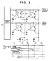
- Each pixel includes a photodiode 1, a transfer switch 2, a reset switch 3, a pixel amplifier 4, and a row selection switch 5 and a plurality of such pixels are connected as shown in Fig. 3. Note, only four pixels are shown in Fig. 3, however, a number of pixels are arranged in practice.
- a source follower configured with a source of load current 7 and the pixel amplifier 4 starts operating, and signals of a selected row are transferred to respective vertical output lines 6.
- the signals are stored in signal storage unit 11 via respective transfer gates 8.
- the signals, temporarily stored in the signal storage unit 11, are sequentially transferred to an output unit (not shown) via a horizontal scan circuit 12.
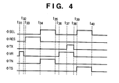
- a signal ⁇ RES becomes high at t 21
- the gate of the pixel amplifier 4 is reset to a reset potential (potential of pulse ⁇ RES minus threshold potential).
- a signal ⁇ SEL becomes high at time t 22
- the source follower configured with the pixel amplifier 4 and the source of load current 7, starts operating. Accordingly, noise corresponding to the reset potential appears on the corresponding vertical output line 6, and is temporarily stored in the signal storage unit 11 by changing a signal ⁇ TN to high as well as turning a transfer gate 13 on.
- the signals ⁇ SEL and ⁇ TN are changed to low at time t 23 , and the potential of the vertical output line 6 decreases as load current is supplied from the source of current 7.
- a transfer signal ⁇ TX becomes high at time t 24 , and photo-charge is transferred from each photodiode 1 to the gate of the pixel amplifier 4.
- the pixel amplifier 4 operates in the triode region. Therefore, the gate capacitance of the pixel amplifier becomes the maximum. Thereafter, the signal ⁇ TX is changed to low at time t 25 , then the signals ⁇ SEL and ⁇ TS are changed to high at time t 26 , and the photo-charge are read out.
- Each pixel includes a photodiode 1, a transfer switch 2, a reset switch 3, a pixel amplifier 4, and a row selection switch 5 and a plurality of such pixels are connected as shown in Fig. 5. Note, only four pixels are shown in Fig. 5, however, a number of pixels are arranged in practice.
- a source follower configured with a source of load current 7 and the pixel amplifier 4, starts operating, and signals of a selected row are transferred to respective vertical output lines 6.
- the signals are stored in signal storage unit 11 via respective transfer gates 8.
- the signals are sequentially transferred to an output unit (not shown) via a horizontal scan circuit 12. Further, vertical-output-line reset switches 9 for resetting the vertical output lines 6 to a fixed potential are also provided. Differences between Fig. 5 and Fig. 3 are that the vertical-output-line reset switches 9 are provided and a reset pulse ⁇ VR is supplied to the gate of the reset switches 9 in Fig. 5.
- the signal ⁇ VR becomes high at t 31 , and the vertical output lines 6 are reset to a fixed potential (ground potential in the third embodiment).
- a signal ⁇ RES becomes high at t 33 , then the gate of the pixel amplifier 4 is reset to a reset potential.
- the signal ⁇ RES is changed to low, and signals ⁇ SEL and ⁇ TN become high at time t 34 .
- the source follower configured with the pixel amplifier 4 and the source of load current 7, starts operating, and noise corresponding to the reset potential appears on the corresponding vertical output line 6, and is temporarily stored in the signal storage unit 11 by turning on the transfer gate 13.
- the signal ⁇ VR becomes high at time t 36 , and the vertical output lines 6 are again reset to the ground potential.
- the transfer signal ⁇ TX becomes high at time t 37 , in turn, photo-charge is transferred from the photodiode 1 to the gate of the pixel amplifier 4.
- the source of the pixel amplifier (MOS FET) 4 is fixed to the ground potential to which the vertical output lines 6 are reset. Further, since the drain of the pixel amplifier 4 is not supplied with a voltage, the operation of the pixel amplifier 4 is limited to the triode region.
- the signals ⁇ SEL and ⁇ TS are changed to high at time t 39 , and the photo-charge is transferred to the corresponding vertical output line 6, further, read out to the signal storage unit 11 by turning on the transfer gate 8.
- the vertical output lines 6 can be reset, therefore, there is no such limitation as described above associated with the configuration of the photoelectric conversion element as described in the second embodiment.
- the potential of the vertical output line 6 changes while the gate potential of the pixel amplifier 4 is in the floating state, a feed-back phenomenon is caused by gate-source capacitance of the pixel amplifier 4.
- the potential of the vertical output line 6 always increases from the ground potential, the ratio of the feed-back voltage to the voltage of the photo-charge is kept constant, and the photo-charge output is kept linear as an additional effect.
- the maximum allowable charge Qsat is increased by 13% according to the third embodiment, since the gate capacitance of the pixel amplifier 4 is maximum when transferring photo-charge to the gate of the pixel amplifier 4.
- Each pixel includes a photodiode 1, a transfer switch 2, a reset switch 3, a pixel amplifier 4, and a row selection switch 5 and a plurality of such pixels are connected as shown in Fig. 7. Note, only four pixels are shown in Fig. 7, however, a number of pixels are arranged in practice.
- the pixel amplifier 4 is connected to a corresponding vertical output line 6 via the row selection switch 5, and when the pixel amplifier 4 and the row selection switch 5 are turned on the pixel amplifier 4, with a resistor 47, operates as an inverse amplifier.
- vertical-output-line reset switches 9 for resetting the vertical output lines 6 to a fixed potential (ground potential in the fourth embodiment) are also provided.
- the pixel amplifier 4 in Fig. 7 differs from the pixel amplifier 4 in Fig. 5 in that it operates as an inverse amplifier with the resistor 47.
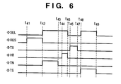
- a signal ⁇ RES becomes high at t 41
- the gate of the pixel amplifier 4 is reset to a reset potential.
- signals ⁇ SEL and ⁇ TN become high at time t 42
- the transfer gate 13 is turned on, and noise is read out.
- a signal ⁇ VR is changed to high at time t 44 , and the vertical output line 6 and the drain of the pixel amplifier 4 are reset to the ground potential.
- the signals ⁇ SEL and ⁇ VR are changed to low at time t 45 , accordingly, the drain of the pixel amplifier 4 is put into the floating state while maintaining the ground potential. At this time, the source of the pixel amplifier 4 is grounded, thus, the operation of the pixel amplifier 4 is limited to the triode region.
- a signal ⁇ TX becomes high at time t 46 , and photo-charge is transferred from the photodiode 1 to the gate of the pixel amplifier 4. Subsequently, the signal ⁇ TX is changed to low at time t 47 , the row selection signal ⁇ SEL and the signal ⁇ TS are changed to high at time t 48 . Accordingly, the transfer gates 8 are turned on and the photo-charge signals are read out. Thereafter, the noise signals and the photo-charge signals stored in a signal storage unit 11 are sequentially outputted via a horizontal scan circuit 12 in accordance with a horizontal scan signal ⁇ H(1, 2).
- the pixel amplifier 4 is in the triode state while transferring photo-charge to the gate of the pixel amplifier 4, and the maximum allowable charge Qsat is increased by 25% comparing to the conventional operation method.
- Each pixel includes a photodiode 1, a transfer switch 2, a reset switch 3, a pixel amplifier 4, and a row selection switch 5 and a plurality of such pixels are connected as shown in Fig. 9. Note, only four pixels are shown in Fig. 5, however, a number of pixels are arranged in practice.
- a source follower configured with a source of load current 7 and the pixel amplifier 4, starts operating, and signals of a selected row are transferred to respective vertical output lines 6.
- the signals are stored in signal storage unit 11 via respective transfer gates 8.
- the signals are sequentially transferred to an output unit (not shown) via a horizontal scan circuit 12. Further, vertical-output-line reset switches 9 for resetting the vertical output lines 6 to a fixed potential are also provided. Differences between Fig. 9 and Fig. 5 are that the row selection switch 5 is connected in the side of the source of the pixel amplifier 4, and a noise signal and a photo-charge signal are both read out to the corresponding vertical output line 6 via the row selection switch 5.
- a signal ⁇ RES becomes high at t 51
- the gate of the pixel amplifier 4 is reset to a reset potential.
- signals ⁇ SEL and ⁇ TN become high at time t 52
- noise is read out to the signal storage unit 11.
- the signal ⁇ TN is changed to low at time t 53
- a signal ⁇ VR is changed to high at time t 54 , thereby the vertical output line 6 is reset.
- the signal ⁇ SEL is kept high, the potential at the source of the pixel amplifier 4 is simultaneously reset and fixed to the ground potential.
- the signal ⁇ TX becomes high at time t 55 , and photo-charge is transferred from the photodiode 1 to the gate of the pixel amplifier 4.
- the gate potential of the pixel amplifier 4 decreases; however, since the source of the pixel amplifier 4 is fixed to the ground potential through the row selection switch 5, the pixel amplifier 4 is always in the on-state during transferring the photo-charge.
- the signals ⁇ VR and ⁇ TX are changed to low at time t 56 and a signal ⁇ TS is changed to high at time t 57 , thereby the photo-charge signal is read out to the signal storage unit 11. Thereafter, the signals ⁇ SEL and ⁇ TS are changed to low to finish reading operation of one row, and the process proceeds to operation of reading the next row.
- the maximum allowable charge Qsat is increased by 43% comparing to the conventional operation method.
- the solid-state image sensing apparatus has a vertical-output-line reset switches 9, however, they may be omitted if the sources of load current 7 supply sufficiently large current and the source of the pixel amplifiers 4 are quickly decreased to the ground potential before transferring photo-charges to the gate of the pixel amplifiers 4.
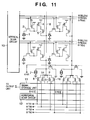
- Each pixel includes a photodiode 1, a transfer switch 2, a reset switch 3, a pixel amplifier 4, and a row selection switch 5 and a plurality of such pixels are connected as shown in Fig. 11, similarly to Fig. 9. Note, only four pixels are shown in Fig. 11, however, a number of pixels are arranged in practice.
- a source follower configured with a source of load current 7 and the pixel amplifier 4, starts operating, and signals of a selected row are transferred to respective vertical output line 6.
- the signals are stored in signal storage unit 11 via respective transfer gates 8, 14, 15, or 16.
- the signals, temporarily stored in the signal storage unit 11, are sequentially transferred to an output unit via a horizontal scan circuit 12. Further, vertical-output-line reset switches 9 for resetting the vertical output lines 6 to a fixed potential are also provided.
- signals in the even-number rows and signals in the odd-number rows are separately transferred to the signal storage unit 11 using the transfer gates 8, 14, 15 and 16. Accordingly, it is possible to read out signals of two rows during horizontal blanking period.
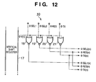
- Fig. 12 is a view showing a configuration of a part of a vertical scan circuit 10 of the solid-state image sensing apparatus shown in Fig. 11.
- a signal ⁇ SEL1 for selecting the odd-number rows and a signal ⁇ SEL2 for selecting the even-number rows which are independently provided signals of two rows are transferred to the signal storage unit 11 in the single horizontal blanking period.
- the vertical scan circuit 10 includes a vertical shift register 17 which outputs a pulse signal V(n) for selecting a n-th pair of adjoining odd- and even-number rows, and plural sets of NOR gates 18 to 21, each pair corresponds to each even-and-odd-number-row pair.
- a pulse signal ⁇ V(n) from the vertical shift register 17, configured within the vertical scan circuit 10, is inputted to one terminal of each of the NOR gates 18 to 21 of the n-th set, and the row selection signals ⁇ SEL1 and ⁇ SEL2, a reset signal ⁇ RES, and a transfer signal ⁇ TX, all of which are generated in the vertical scan circuit 10, are provided to the other terminals of the NOR gates 18 to 21, respectively.
- the NOR gates 18 to 21 When the pulse signal V(n), selecting the n-th pair of rows, is inputted, then the NOR gates 18 to 21 outputs selection signals ⁇ SEL1(n) and ⁇ SEL2(n) to the corresponding rows, and a reset signal ⁇ RES(n) and a transfer signal ⁇ TX(n) to both of the even and rows of the n-th pair for operating the respective pixels.
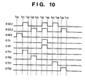
- the signals ⁇ SEL1 and ⁇ TN1 becomes high at time t 61 , and noise in the odd-number row is read out to the signal storage unit 11.
- the signals ⁇ SEL1 and ⁇ TN1 are changed to low at time t 62 , and the signals ⁇ SEL2 and ⁇ TN2 are changed to high at time t 63 , and noise in the even-number row is read out to the signal storage unit 11 by the time t 64 .
- the reset potential is the ground potential.
- a signal ⁇ TX is changed to high, and photo-charge is transferred from the photodiode 1 to the gate of the pixel amplifier 4.
- the gate potential of the pixel amplifier 4 decreases, however, since the signals ⁇ SEL1 and ⁇ SEL2 are high and the row selection switch 5 is on, the source of the pixel amplifier 4 is fixed to the ground voltage through the row selection switch 5 and the pixel amplifier 4 is always in the on-state during transferring the photo-charge.
- Photo-charges in an odd-number row and an even-number row are read out to the signal storage units 11 by sequentially changing the signals ⁇ SEL1 and ⁇ TS1, and ⁇ SEL2 and ⁇ TS2 to high (at times t 67 , t 68 , t 69 , t 70 ).
- photo-charge signals are sequentially read out for a frame image.
- the pixel amplifier 4 since the source of the pixel amplifier 4 is in the floating state while transferring photo-charge to the gate of the pixel amplifier 4, the pixel amplifier 4 is turned off when large photo-charge is transferred. In contrast, the pixel amplifier 4 is fixed to the on-state in the sixth embodiment, the maximum allowable charge Qsat is increased by 45% comparing to the conventional operation method.
- photo-charge is transferred to the gate of a MOS transistor, used as the pixel amplifier 4, in the optimum operation region of the MOS transistor by supplying operation pulses in various ways, the MOS transistor operates in the triode region where the MOS transistor operates linearly, thereby it is possible to read out the photo-charge while widening a dynamic range of the pixel amplifier 4.
- the foregoing embodiments can be generally applied to any type of solid-state image sensing apparatus having a photoelectric conversion element, a field effect transistor whose gate receives photo-charge, and a transfer switch for controlling the connection between the photoelectric conversion element and the gate of the field effect transistor in each pixel unit, and the maximum allowable charge Qsat which can be dealt with by a source-follower type amplifier and the field effect transistor for inverse amplification is increased, thereby the dynamic range is widened. Accordingly, high-quality image signals of high S/N ratio can be obtained.
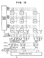
- Fig. 13 is a block diagram illustrating a configuration of a solid-state image sensing apparatus according to the seventh embodiment
- Fig. 14 is a circuit diagram illustrating a basic configuration of a pixel.
- a plurality of such pixels are formed on a single semiconductor substrate made of, e.g., mono-crystalline silicone, in CMOS LSI processing in accordance with a manufacturing technique of a semi-conductor integrated circuit, and collectively called as "CMOS sensor" in general.
- CMOS sensor CMOS sensor
- the anode of a photodiode PD which generates photo-charge is grounded in the seventh embodiment.
- the cathode of the photodiode PD is connected to the gate of a MOS transistor M3 for amplification (referred to as “MOS amplifier” hereinafter) via a charge transfer switch TX.
- MOS amplifier MOS amplifier
- the source of a MOS transistor M1 referred to as "reset MOS” hereinafter
- a reset voltage VR is provided to the drain of the reset MOS M1 to a MOS transistor M2 (referred to as "MOS selector” hereinafter) to select a row to which an operation voltage VDD is applied.
- the gates of charge transfer switches TX of the pixels S11 to Smn are connected to first row selection lines (vertical scan lines) TX1 to TXm each extending in the horizontal direction.
- first row selection lines vertical scan lines
- the gates of charge transfer switches TX of pixels S11 to S1n in the first row are connected to the first row selection line TX1
- the gates of charge transfer switches TX of pixels Sil to Sin (i is an arbitrary integer) in the i-th row are connected to the first row selection line TXi.
- the gates of the MOS transistors M1 of the pixels S11 to S1n are connected to a second row selection line (vertical scan line) RES1 which also extends in the horizontal direction.
- the gates of MOS transistors M1 of pixels Sil to Sin in the 1-th row are connected to the second row selection line RESi.
- the gates of the MOS transistors M3 of the pixels S11 to S1n are connected to a third row selection line (vertical scan line) SELl which also extends in the horizontal direction.
- the gates of MOS transistors M3 of pixels Sil to Sin in the i-th row are connected to the third row selection line SELi.
- These first to third row selection lines TXi, RESi, and SELi are connected to a vertical scan circuit 71, and applied with voltage signals in accordance with the following operation timing shown in Fig. 15.
- signals ⁇ TX1 to ⁇ TXm, ⁇ RES1 to ⁇ RESm, and ⁇ SEL1 to ⁇ SELm are provided from the vertical scan circuit 71.
- the sources of the MOS transistors M3 of the pixels S11 to Sml are connected to a vertical signal line V1 which extends in the vertical direction.
- the sources of the MOS transistors M3 of pixels Slj to Smj (j is an arbitrary integer) in the j-th column are connected to a vertical signal line Vj.
- the vertical signal line V1 is connected to a constant current source I1 which is a load, as well as applied with a vertical line reset voltage VVR via a MOS transistor M8, when it is on, for resetting the vertical signal line V1.
- the vertical signal line V1 is connected to a capacitor CTN for temporarily storing a noise signal via a noise signal transfer switch M4, and to a capacitor CTS for temporarily storing a photo-charge signal via a photo-charge signal transfer switch M5.
- the other side of the capacitors CTN and CTS are grounded.
- a node VIN between the noise signal transfer switch M4 and the capacitor CTN, and a node VIS between the photo-charge signal transfer switch M5 and the capacitor CTS are provided with a voltage VRCT via capacitor reset switches M9 and M10, respectively, when they are on, further, connected to a differential block 73 for taking the difference between the photo-charge signal and the noise signal via horizontal transfer switches M6 and M7, respectively.
- the gates of the horizontal transfer switches M6 and M7 are both connected to a column selection line H1, further connected to a horizontal scan circuit 72.
- the identical circuit for reading signals is configured.
- the gates of the vertical line reset switches M8, the noise signal transfer switches M4, and the photo-charge signal transfer switches M5, which are provided for each of the vertical signal lines V1 to Vn, are connected to lines VRES, TN, and TS, respectively, to which signals ⁇ VMS, ⁇ TN, and ⁇ TS are provided, respectively.
- the signal ⁇ RES1 applied to the gates of the reset MOS M1 in the first row, and the signal ⁇ VRES, applied to the gates of the MOS transistors M8, become high before time t 71 . Accordingly, the gates of the MOS amplifier M3 are reset to the voltage VR, and the vertical signal lines V1 to Vn are reset to the voltage VVR.
- the signal ⁇ RES1, applied to the gates of the reset MOS M1, and the signal ⁇ VRES, applied to the gates of the MOS transistors M8, are changed to low at time t 71 , the signal ⁇ SEL1, applied to the gates of the MOS selectors M2 in the first row, and the signal ⁇ TN applied to the gates of the noise signal transfer switches M4 become high at time t 72 .
- the reset signal VR is superposed with a reset noise, and multiplied by a gain A by the MOS amplifiers M3, further shifted by a gate-source voltage VGS of the MOS amplifiers. Then, the resultant noise signals are read out to the respective capacitors CTN.
- the noise signal (voltage) V1N is expressed by the following equation.
- VIN A ⁇ (VR - VGS)
- the gate-source voltage VGS varies depending upon a threshold voltage Vth of each MOS amplifier M3 in each pixel, as described above.
- the voltages of the vertical signal lines V1 to Vn gradually decrease as they are discharged at a time constant determined by parasitic capacitances CP of the vertical signal lines V1 to Vn and the constant current sources (Il). Since the constant current source (Il) is connected to each vertical signal line, even though the voltage VVR for resetting the vertical signal lines V1 to Vn is set to a substantially high voltage and the MOS amplifiers M3 are in the off state at the start of reading signals, the voltages of the vertical signal lines V1 to Vn decrease due to the constant current, and the MOS amplifiers M3 are eventually turned on, thus the signals are read out. Therefore, there is no limitation on the level of reset voltage for the vertical signal lines V1 to Vn.
- the signal ⁇ VRES, applied to the gates of the MOS transistors M8, are changed to high at time t 74 , and the vertical signal lines V1 to Vn are reset to the voltage VVR again. Accordingly, an initial voltage of the vertical signal lines V1 to Vn for reading photo-charge is set to the same voltage as that for reading the noise signals. Therefore, when it is not possible to take a sufficient period since noise signals are read until photo-charges are transferred, an initial potential of the vertical signal line when outputting a noise signal and an initial potential of the vertical signal line when outputting a photo-charge signal are identical; therefore, noise reduction operation, which will be explained later, is performed at high precision.
- the signal ⁇ TX1 applied to the gates of the charge transfer switches TX in the first row becomes high at time t 75 , and the photo-charge generated by the photodiode PD is transferred to the gates of the respective MOS amplifiers M3.
- the signals ⁇ SEL1, applied to the gates of the MOS selectors M2 in the first row, and the signal ⁇ TS applied to the gates of the photo-charge signal transfer switches M5 become high at time t 78 .
- the photo-charge signal (voltage) Vsig is amplified by the gain A of the corresponding MOS amplifier M3 and shifted by a gate-source voltage of the MOS amplifier M3, and a resultant voltage is read out to the capacitor CTS.
- the output voltage V1S is expressed by the following equation (7).
- V1S A ⁇ (Vsig - VGS)
- the signal ⁇ SEL1, applied to the gates of the MOS selectors M2, and the signal ⁇ TS, applied to the gates of the photo-charge signal transfer switches M5, are changed to low at time t 79 .
- the voltages of the vertical signal lines V1 to Vn gradually decrease as they are discharged at a time constant determined by parasitic capacitances Cp of the vertical signal lines V1 to Vn and the constant current sources (Il).
- the noise signals and photo-charge signals of the pixels S11 to S1n, connected to the first row are stored in the capacitors CTN for storing noise signals and the capacitors CTS for storing photo-charge signals, each provided for the respective columns.
- the differential block 73 takes the differences between the photo-charge signals V1S to VnS and the corresponding noise signals V1N to VnN, and sequentially outputs the differences as a voltage VOUT.
- the output voltage VOUT of the first column is expressed by the following equation, obtained by subtracting equation (6) from equation (7).
- the seventh embodiment in reading a noise signal and a photo-charge signal to the capacitors CTN and CTS, a capacitive division configuration is not adopted; thus, the capacitances of the capacitors CTN and CTS are not affected by the parasitic capacitance of the vertical output lines, and a small-size solid-state image sensing apparatus as well as high speed reading of the solid-state image sensing apparatus are realized.
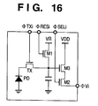
- Fig. 16 is a circuit diagram illustrating a basic configuration of a pixel according to the eighth embodiment of the present invention. Referring to Fig. 16, the basic configuration of each pixel is explained. In Fig. 16, units and elements as those shown in Fig. 14 are referred to by the same references, and a plurality of such pixels are arranged as shown in Fig. 13. Pixels and peripheral circuits are manufactured in CMOS LSI processing, and collectively called as "CMOS sensor".
- Photodiodes may be formed while forming a source-drain diffusion layer.
- the photodiodes in the pixels according to the eighth embodiment of the present invention are complete depletion type buried photodiodes, processes for forming the photodiodes are added to standard CMOS LSI processing. With the complete depletion type photodiodes, photo-charges of good linearity can be obtained.
- the anode of the photodiode PD which generates photo-charge is grounded.
- the cathode of the photodiode PD is connected to the gate of the MOS amplifier M3 via the charge transfer switch TX.
- the source of the reset MOS M1 for resetting the gate of the MOS amplifier M3 is connected, and the drain of the reset MOS M1 is applied with the reset voltage VR.
- the drain of the MOS amplifier M3 is applied with the operation voltage VDD, and the source is connected to the MOS selector M2 for connecting the MOS amplifier M3 to the vertical signal line. Since the MOS selector M2 is connected to the source of the MOS amplifier M3, it is possible to widen the dynamic range in the VDD side, compared against the pixel circuit shown in Fig. 14.
- noise signals of the respective pixels are read out in a period between time t 72 and time t 73
- photo-charge signals are read out in a period between time t 78 and time t 79
- the output signals VOUT which are the differences between the photo-charge signals and the noise signals, are obtained by the differential block 73.
- the output signals VOUT do not include components of threshold voltages Vth of the MOS transistors M1 and M3, thus, fixed pattern noise of the CMOS sensor, which has been considered as a problem, is reduced.
- the both terms Vsig and VR in the right hand side of equation (8) include reset noise, therefore, the reset noise is canceled out.
- a component of the photo-charge generated by the photodiode PD is converted to a voltage, i.e., the output voltage VOUT. Therefore, noise due to variation in the threshold voltage of the amplifier is also reduced, thereby an image signal of high S/N ratio can be obtained.
- CMOS sensor including the vertical scan circuit and the horizontal scan circuit becomes possible, which enables to produce a small-sized image sensor consuming low electrical energy.
- a load for a MOS amplifier is provided and a signal is temporary stored in a capacitor via a source follower, thus, better sensitivity is achieved with a smaller capacitance of the capacitor than a clamping capacitor C1 (Fig. 17). Accordingly, the chip size of a solid-state image sensing apparatus can be reduced.
- a switch for resetting each vertical signal line is provided and, in advance of reading of a photo-charge signal after reading a noise signal, the vertical signal line is reset to a predetermined reset voltage.
- the reset voltage for resetting the vertical signal line is set relatively high and the MOS amplifier is in the off state in an early stage of reading a photo-charge signal
- the voltage of the vertical signal line decreases in response to the constant current of the load, and the MOS amplifier is eventually turned on. Accordingly, the photo-charge signal is read out. Therefore, there is no limitation on the reset voltage to be applied to the vertical signal line.
- each vertical signal line is reset before reading noise as well as before reading photo-charge, thus the vertical signal line is refreshed each time signals is read from a pixel. Accordingly, it is possible to restrict interference between adjoining pixels as well as prevent cross modulation and blooming.
- NMOS transistors are mainly used in the circuits, however, the present invention is not limited to this, and it is possible to use PMOS transistors in place of the NMOS transistors. Further, the field effect transistors are not limited to the MOS type.
Landscapes
- Engineering & Computer Science (AREA)
- Multimedia (AREA)
- Signal Processing (AREA)
- Solid State Image Pick-Up Elements (AREA)
- Transforming Light Signals Into Electric Signals (AREA)
Applications Claiming Priority (4)
| Application Number | Priority Date | Filing Date | Title |
|---|---|---|---|
| JP11561398 | 1998-04-24 | ||
| JP11561398A JP3667081B2 (ja) | 1998-04-24 | 1998-04-24 | 固体撮像装置とその駆動方法 |
| JP16992498A JP3667094B2 (ja) | 1998-06-17 | 1998-06-17 | 固体撮像装置 |
| JP16992498 | 1998-06-17 |
Publications (3)
| Publication Number | Publication Date |
|---|---|
| EP0952730A2 true EP0952730A2 (fr) | 1999-10-27 |
| EP0952730A3 EP0952730A3 (fr) | 2000-11-08 |
| EP0952730B1 EP0952730B1 (fr) | 2004-12-22 |
Family
ID=26454101
Family Applications (1)
| Application Number | Title | Priority Date | Filing Date |
|---|---|---|---|
| EP99303078A Expired - Lifetime EP0952730B1 (fr) | 1998-04-24 | 1999-04-21 | Dispositif à l'état solide de prise de vue |
Country Status (3)
| Country | Link |
|---|---|
| US (1) | US6963372B1 (fr) |
| EP (1) | EP0952730B1 (fr) |
| DE (1) | DE69922730T2 (fr) |
Cited By (6)
| Publication number | Priority date | Publication date | Assignee | Title |
|---|---|---|---|---|
| WO2000064142A1 (fr) * | 1999-04-20 | 2000-10-26 | Fraunhofer-Gesellschaft zur Förderung der angewandten Forschung e.V. | Circuit pour le traitement d'un signal analogique temporel discret et capteur d'images |
| EP1143708A1 (fr) * | 2000-02-28 | 2001-10-10 | Canon Kabushiki Kaisha | Dispositif de prise d'images |
| EP1154310A2 (fr) | 2000-04-12 | 2001-11-14 | Semiconductor Energy Laboratory Co., Ltd. | Dispositif à semiconducteur et méthode pour le commander |
| US7030922B2 (en) | 2001-07-17 | 2006-04-18 | Canon Kabushiki Kaisha | Image pickup apparatus which reduces noise generated in an amplifier transistor |
| EP2290953A3 (fr) * | 2001-07-12 | 2012-04-18 | Canon Kabushiki Kaisha | Dispositif de prise de vue |
| TWI413241B (zh) * | 2005-02-07 | 2013-10-21 | 濱松赫德尼古斯股份有限公司 | Solid-state imaging device |
Families Citing this family (20)
| Publication number | Priority date | Publication date | Assignee | Title |
|---|---|---|---|---|
| JP4006075B2 (ja) * | 1998-01-30 | 2007-11-14 | キヤノン株式会社 | Cmosセンサ及び撮像システム |
| EP0999698B1 (fr) | 1998-11-02 | 2013-06-19 | Canon Kabushiki Kaisha | Dispositif de prise de vues à l'état solide et méthode de réinitialisation de celui-ci |
| JP3524440B2 (ja) * | 1999-07-27 | 2004-05-10 | キヤノン株式会社 | 固体撮像装置とその駆動方法 |
| JP3750502B2 (ja) * | 2000-08-03 | 2006-03-01 | ソニー株式会社 | 固体撮像装置およびカメラシステム |
| JP3667214B2 (ja) * | 2000-08-25 | 2005-07-06 | キヤノン株式会社 | 固体撮像装置およびその駆動方法 |
| FR2814242B1 (fr) * | 2000-09-19 | 2002-12-20 | France Telecom | Dispositif de mesure ponctuelle d'un champ magnetique radiofrequence d'amplitude et de frequence constantes |
| JP4154268B2 (ja) * | 2003-03-27 | 2008-09-24 | キヤノン株式会社 | 撮像装置 |
| JP4194544B2 (ja) * | 2003-12-05 | 2008-12-10 | キヤノン株式会社 | 固体撮像装置及び固体撮像装置の駆動方法 |
| JP3814609B2 (ja) * | 2003-12-12 | 2006-08-30 | キヤノン株式会社 | 撮像装置、及び撮像装置の駆動方法 |
| JP4018644B2 (ja) | 2004-01-29 | 2007-12-05 | キヤノン株式会社 | 光電変換装置及び同光電変換装置を用いた撮像システム |
| US7385636B2 (en) * | 2004-04-30 | 2008-06-10 | Eastman Kodak Company | Low noise sample and hold circuit for image sensors |
| JP4144892B2 (ja) * | 2006-08-28 | 2008-09-03 | キヤノン株式会社 | 光電変換装置及び撮像装置 |
| FR2910710B1 (fr) * | 2006-12-21 | 2009-03-13 | St Microelectronics Sa | Capteur d'image cmos a photodiode piegee a faible tension d'alimentation |
| JP5173503B2 (ja) * | 2008-03-14 | 2013-04-03 | キヤノン株式会社 | 撮像装置及び撮像システム |
| JP5730030B2 (ja) * | 2011-01-17 | 2015-06-03 | 浜松ホトニクス株式会社 | 固体撮像装置 |
| DE102011120099B4 (de) | 2011-12-02 | 2024-05-29 | Arnold & Richter Cine Technik Gmbh & Co. Betriebs Kg | Bildsensor und Verfahren zum Auslesen eines Bildsensors |
| JP6319946B2 (ja) * | 2013-04-18 | 2018-05-09 | キヤノン株式会社 | 固体撮像装置及び撮像システム |
| CN112437238B (zh) * | 2019-08-26 | 2023-06-09 | 天津大学青岛海洋技术研究院 | 一种低kTC噪声三维图像传感器锁相像素结构 |
| US12526544B2 (en) * | 2021-03-24 | 2026-01-13 | Sony Semiconductor Solutions Corporation | Image sensor assembly, solid-state imaging device and time-of-flight sensor assembly |
| JP2023176514A (ja) * | 2022-05-31 | 2023-12-13 | キヤノン株式会社 | 光電変換装置、光電変換装置の駆動方法 |
Family Cites Families (8)
| Publication number | Priority date | Publication date | Assignee | Title |
|---|---|---|---|---|
| JPS5848577A (ja) | 1981-09-18 | 1983-03-22 | Semiconductor Res Found | 固体撮像装置の画像信号読出し方法 |
| JPH0461573A (ja) | 1990-06-29 | 1992-02-27 | Hitachi Ltd | 画素増幅型固体撮像素子 |
| JP3018546B2 (ja) * | 1991-03-18 | 2000-03-13 | ソニー株式会社 | 固体撮像装置 |
| JPH0518309A (ja) | 1991-07-12 | 1993-01-26 | Daihatsu Motor Co Ltd | エンジン冷却水温の検出値校正装置 |
| JPH07255013A (ja) | 1994-01-31 | 1995-10-03 | Sony Corp | 固体撮像装置 |
| US5933189A (en) * | 1995-03-09 | 1999-08-03 | Nikon Corporation | Solid state image pickup apparatus |
| JP3774499B2 (ja) * | 1996-01-24 | 2006-05-17 | キヤノン株式会社 | 光電変換装置 |
| US6037577A (en) * | 1997-03-11 | 2000-03-14 | Kabushiki Kaisha Toshiba | Amplifying solid-state image pickup device and operating method of the same |
-
1999
- 1999-04-14 US US09/291,006 patent/US6963372B1/en not_active Expired - Fee Related
- 1999-04-21 EP EP99303078A patent/EP0952730B1/fr not_active Expired - Lifetime
- 1999-04-21 DE DE69922730T patent/DE69922730T2/de not_active Expired - Lifetime
Cited By (23)
| Publication number | Priority date | Publication date | Assignee | Title |
|---|---|---|---|---|
| US7295236B1 (en) | 1999-04-20 | 2007-11-13 | Fraunhofer-Gesellschaft Zue Foerderung Der Angewandten Forschung E.V. | Circuit for processing a time-discrete analog signal and image sensor |
| US8830365B2 (en) | 1999-04-20 | 2014-09-09 | Fraunhofer-Gesellschaft Zur Foerderung Der Angewandten Forschung E.V. | Circuit for processing a time-discrete analog signal and image sensor |
| WO2000064142A1 (fr) * | 1999-04-20 | 2000-10-26 | Fraunhofer-Gesellschaft zur Förderung der angewandten Forschung e.V. | Circuit pour le traitement d'un signal analogique temporel discret et capteur d'images |
| US7961236B2 (en) | 1999-04-20 | 2011-06-14 | Fraunhofer-Gesellschaft Zur Foerderung Der Angewandten Forschung E.V. | Circuit for processing a time-discrete analog signal and image sensor |
| US8085330B2 (en) | 2000-02-28 | 2011-12-27 | Canon Kabushiki Kaisha | Image pickup apparatus |
| US6965408B2 (en) | 2000-02-28 | 2005-11-15 | Canon Kabushiki Kaisha | Solid-state image pickup device having a photoelectric conversion unit and a punch-through current suppression circuit |
| US7545426B2 (en) | 2000-02-28 | 2009-06-09 | Canon Kabushiki Kaisha | Image pickup apparatus |
| EP1143708A1 (fr) * | 2000-02-28 | 2001-10-10 | Canon Kabushiki Kaisha | Dispositif de prise d'images |
| US8717475B2 (en) | 2000-02-28 | 2014-05-06 | Canon Kabushiki Kaisha | Image pickup apparatus |
| US8355065B2 (en) | 2000-04-12 | 2013-01-15 | Semiconductor Energy Laboratory Co., Ltd. | Semiconductor device and method of driving the same |
| US9019408B2 (en) | 2000-04-12 | 2015-04-28 | Semiconductor Energy Laboratory Co., Ltd. | Semiconductor device and method of driving the same |
| US9568615B2 (en) | 2000-04-12 | 2017-02-14 | Semiconductor Energy Laboratory Co., Ltd. | Semiconductor device and method of driving the same |
| US8203636B2 (en) | 2000-04-12 | 2012-06-19 | Semiconductor Energy Laboratory Co., Ltd. | Semiconductor device and method of driving the same |
| US9274236B2 (en) | 2000-04-12 | 2016-03-01 | Semiconductor Energy Laboratory Co., Ltd. | Semiconductor device and method of driving the same |
| EP1154310A2 (fr) | 2000-04-12 | 2001-11-14 | Semiconductor Energy Laboratory Co., Ltd. | Dispositif à semiconducteur et méthode pour le commander |
| EP1154310A3 (fr) * | 2000-04-12 | 2009-12-02 | Semiconductor Energy Laboratory Co., Ltd. | Dispositif à semiconducteur et méthode pour le commander |
| US7808535B2 (en) | 2000-04-12 | 2010-10-05 | Semiconductor Energy Laboratory Co., Ltd. | Semiconductor device and method of driving the same |
| US8743250B2 (en) | 2000-04-12 | 2014-06-03 | Semiconductor Energy Laboratory Co., Ltd. | Semiconductor device and method of driving the same |
| US8553120B2 (en) | 2001-07-12 | 2013-10-08 | Canon Kabushiki Kaisha | Solid state image pickup apparatus |
| US9055211B2 (en) | 2001-07-12 | 2015-06-09 | Canon Kabushiki Kaisha | Image pickup apparatus |
| EP2290953A3 (fr) * | 2001-07-12 | 2012-04-18 | Canon Kabushiki Kaisha | Dispositif de prise de vue |
| US7030922B2 (en) | 2001-07-17 | 2006-04-18 | Canon Kabushiki Kaisha | Image pickup apparatus which reduces noise generated in an amplifier transistor |
| TWI413241B (zh) * | 2005-02-07 | 2013-10-21 | 濱松赫德尼古斯股份有限公司 | Solid-state imaging device |
Also Published As
| Publication number | Publication date |
|---|---|
| EP0952730B1 (fr) | 2004-12-22 |
| EP0952730A3 (fr) | 2000-11-08 |
| DE69922730T2 (de) | 2005-12-15 |
| DE69922730D1 (de) | 2005-01-27 |
| US6963372B1 (en) | 2005-11-08 |
Similar Documents
| Publication | Publication Date | Title |
|---|---|---|
| EP0952730B1 (fr) | Dispositif à l'état solide de prise de vue | |
| US10171760B2 (en) | Solid-state imaging device, method for driving solid-state imaging device, and electronic apparatus using an amplifier and signal lines for low and high gain | |
| US7292276B2 (en) | High-speed solid-state imaging device capable of suppressing image noise | |
| US8624308B2 (en) | Image sensor five transistor pixel element with four control signals | |
| KR101201269B1 (ko) | 고체 촬상 장치, 광센서 및 고체 촬상 장치의 동작 방법 | |
| JP3667094B2 (ja) | 固体撮像装置 | |
| US7030921B2 (en) | Solid-state image-sensing device | |
| US7714920B2 (en) | Solid-state imaging device driving method | |
| US8159586B2 (en) | Solid-state imaging apparatus | |
| KR101900668B1 (ko) | 고체 촬상 소자 및 촬상 장치 | |
| US20080237446A1 (en) | Solid-state image pickup device and method | |
| US20110121162A1 (en) | Solid-state imaging device and differential circuit | |
| KR101031982B1 (ko) | 고상 촬상 디바이스 및 그 구동 방법 | |
| US7399951B2 (en) | Solid-state image-sensing device | |
| US6697114B1 (en) | Triple slope pixel sensor and arry | |
| JP2008258885A (ja) | 撮像装置および撮像装置の駆動方法 | |
| KR20060112223A (ko) | 고체 촬상 장치, 고체 촬상 장치의 구동 방법 및 촬상 장치 | |
| US6822211B2 (en) | Solid-state image-sensing device | |
| US20090046187A1 (en) | Solid-state imaging device | |
| US7889247B2 (en) | Solid-state imaging device, method of driving solid-state imaging device, and imaging apparatus | |
| US7692702B2 (en) | Solid-state imaging device with amplifiers corresponding to signal lines and alternating control voltage | |
| US8120688B2 (en) | Solid state imaging device | |
| EP1175084A2 (fr) | Dispositif de prise d'images à semi-conducteur | |
| JP4746962B2 (ja) | 固体撮像装置及び撮像システム | |
| KR20060041013A (ko) | Cmos 이미지 센서 및 그 구동 방법 |
Legal Events
| Date | Code | Title | Description |
|---|---|---|---|
| PUAI | Public reference made under article 153(3) epc to a published international application that has entered the european phase |
Free format text: ORIGINAL CODE: 0009012 |
|
| AK | Designated contracting states |
Kind code of ref document: A2 Designated state(s): DE FR GB IT NL |
|
| AX | Request for extension of the european patent |
Free format text: AL;LT;LV;MK;RO;SI |
|
| PUAL | Search report despatched |
Free format text: ORIGINAL CODE: 0009013 |
|
| AK | Designated contracting states |
Kind code of ref document: A3 Designated state(s): AT BE CH CY DE DK ES FI FR GB GR IE IT LI LU MC NL PT SE |
|
| AX | Request for extension of the european patent |
Free format text: AL;LT;LV;MK;RO;SI |
|
| 17P | Request for examination filed |
Effective date: 20010321 |
|
| 17Q | First examination report despatched |
Effective date: 20010427 |
|
| AKX | Designation fees paid |
Free format text: DE FR GB IT NL |
|
| GRAP | Despatch of communication of intention to grant a patent |
Free format text: ORIGINAL CODE: EPIDOSNIGR1 |
|
| RTI1 | Title (correction) |
Free format text: SOLID-STATE IMAGE SENSING APPARATUS |
|
| GRAA | (expected) grant |
Free format text: ORIGINAL CODE: 0009210 |
|
| GRAS | Grant fee paid |
Free format text: ORIGINAL CODE: EPIDOSNIGR3 |
|
| AK | Designated contracting states |
Kind code of ref document: B1 Designated state(s): DE FR GB IT NL |
|
| REG | Reference to a national code |
Ref country code: GB Ref legal event code: FG4D |
|
| REF | Corresponds to: |
Ref document number: 69922730 Country of ref document: DE Date of ref document: 20050127 Kind code of ref document: P |
|
| PLBE | No opposition filed within time limit |
Free format text: ORIGINAL CODE: 0009261 |
|
| STAA | Information on the status of an ep patent application or granted ep patent |
Free format text: STATUS: NO OPPOSITION FILED WITHIN TIME LIMIT |
|
| 26N | No opposition filed |
Effective date: 20050923 |
|
| ET | Fr: translation filed | ||
| PGFP | Annual fee paid to national office [announced via postgrant information from national office to epo] |
Ref country code: NL Payment date: 20120425 Year of fee payment: 14 |
|
| PGFP | Annual fee paid to national office [announced via postgrant information from national office to epo] |
Ref country code: FR Payment date: 20120504 Year of fee payment: 14 |
|
| PGFP | Annual fee paid to national office [announced via postgrant information from national office to epo] |
Ref country code: IT Payment date: 20120417 Year of fee payment: 14 |
|
| REG | Reference to a national code |
Ref country code: NL Ref legal event code: V1 Effective date: 20131101 |
|
| REG | Reference to a national code |
Ref country code: FR Ref legal event code: ST Effective date: 20131231 |
|
| PG25 | Lapsed in a contracting state [announced via postgrant information from national office to epo] |
Ref country code: IT Free format text: LAPSE BECAUSE OF NON-PAYMENT OF DUE FEES Effective date: 20130421 Ref country code: NL Free format text: LAPSE BECAUSE OF NON-PAYMENT OF DUE FEES Effective date: 20131101 Ref country code: FR Free format text: LAPSE BECAUSE OF NON-PAYMENT OF DUE FEES Effective date: 20130430 |
|
| PGFP | Annual fee paid to national office [announced via postgrant information from national office to epo] |
Ref country code: DE Payment date: 20150430 Year of fee payment: 17 Ref country code: GB Payment date: 20150424 Year of fee payment: 17 |
|
| REG | Reference to a national code |
Ref country code: DE Ref legal event code: R119 Ref document number: 69922730 Country of ref document: DE |
|
| GBPC | Gb: european patent ceased through non-payment of renewal fee |
Effective date: 20160421 |
|
| PG25 | Lapsed in a contracting state [announced via postgrant information from national office to epo] |
Ref country code: DE Free format text: LAPSE BECAUSE OF NON-PAYMENT OF DUE FEES Effective date: 20161101 Ref country code: GB Free format text: LAPSE BECAUSE OF NON-PAYMENT OF DUE FEES Effective date: 20160421 |