EP0952755A2 - Méthode et dispositif pour former un réseau privé virtuel - Google Patents
Méthode et dispositif pour former un réseau privé virtuel Download PDFInfo
- Publication number
- EP0952755A2 EP0952755A2 EP99250096A EP99250096A EP0952755A2 EP 0952755 A2 EP0952755 A2 EP 0952755A2 EP 99250096 A EP99250096 A EP 99250096A EP 99250096 A EP99250096 A EP 99250096A EP 0952755 A2 EP0952755 A2 EP 0952755A2
- Authority
- EP
- European Patent Office
- Prior art keywords
- vpn
- information
- network
- mpoa
- packet
- Prior art date
- Legal status (The legal status is an assumption and is not a legal conclusion. Google has not performed a legal analysis and makes no representation as to the accuracy of the status listed.)
- Withdrawn
Links
- 238000000034 method Methods 0.000 title claims description 6
- 238000012546 transfer Methods 0.000 claims abstract description 33
- 238000012545 processing Methods 0.000 claims description 19
- 230000005540 biological transmission Effects 0.000 claims description 9
- 238000010586 diagram Methods 0.000 description 11
- 238000006243 chemical reaction Methods 0.000 description 4
- 230000011664 signaling Effects 0.000 description 3
- 241001481828 Glyptocephalus cynoglossus Species 0.000 description 2
- 230000015572 biosynthetic process Effects 0.000 description 1
- 238000013507 mapping Methods 0.000 description 1
- 230000000717 retained effect Effects 0.000 description 1
- 238000012795 verification Methods 0.000 description 1
Images





Classifications
-
- H—ELECTRICITY
- H04—ELECTRIC COMMUNICATION TECHNIQUE
- H04Q—SELECTING
- H04Q11/00—Selecting arrangements for multiplex systems
- H04Q11/04—Selecting arrangements for multiplex systems for time-division multiplexing
- H04Q11/0428—Integrated services digital network, i.e. systems for transmission of different types of digitised signals, e.g. speech, data, telecentral, television signals
- H04Q11/0478—Provisions for broadband connections
-
- H—ELECTRICITY
- H04—ELECTRIC COMMUNICATION TECHNIQUE
- H04L—TRANSMISSION OF DIGITAL INFORMATION, e.g. TELEGRAPHIC COMMUNICATION
- H04L12/00—Data switching networks
- H04L12/54—Store-and-forward switching systems
- H04L12/56—Packet switching systems
- H04L12/5601—Transfer mode dependent, e.g. ATM
- H04L2012/5619—Network Node Interface, e.g. tandem connections, transit switching
- H04L2012/5621—Virtual private network [VPN]; Private-network - network-interface (P-NNI)
-
- H—ELECTRICITY
- H04—ELECTRIC COMMUNICATION TECHNIQUE
- H04Q—SELECTING
- H04Q2213/00—Indexing scheme relating to selecting arrangements in general and for multiplex systems
- H04Q2213/13103—Memory
-
- H—ELECTRICITY
- H04—ELECTRIC COMMUNICATION TECHNIQUE
- H04Q—SELECTING
- H04Q2213/00—Indexing scheme relating to selecting arrangements in general and for multiplex systems
- H04Q2213/13141—Hunting for free outlet, circuit or channel
-
- H—ELECTRICITY
- H04—ELECTRIC COMMUNICATION TECHNIQUE
- H04Q—SELECTING
- H04Q2213/00—Indexing scheme relating to selecting arrangements in general and for multiplex systems
- H04Q2213/13174—Data transmission, file transfer
-
- H—ELECTRICITY
- H04—ELECTRIC COMMUNICATION TECHNIQUE
- H04Q—SELECTING
- H04Q2213/00—Indexing scheme relating to selecting arrangements in general and for multiplex systems
- H04Q2213/1329—Asynchronous transfer mode, ATM
-
- H—ELECTRICITY
- H04—ELECTRIC COMMUNICATION TECHNIQUE
- H04Q—SELECTING
- H04Q2213/00—Indexing scheme relating to selecting arrangements in general and for multiplex systems
- H04Q2213/13296—Packet switching, X.25, frame relay
-
- H—ELECTRICITY
- H04—ELECTRIC COMMUNICATION TECHNIQUE
- H04Q—SELECTING
- H04Q2213/00—Indexing scheme relating to selecting arrangements in general and for multiplex systems
- H04Q2213/13353—Routing table, map memory
-
- H—ELECTRICITY
- H04—ELECTRIC COMMUNICATION TECHNIQUE
- H04Q—SELECTING
- H04Q2213/00—Indexing scheme relating to selecting arrangements in general and for multiplex systems
- H04Q2213/13384—Inter-PBX traffic, PBX networks, e.g. corporate networks
-
- H—ELECTRICITY
- H04—ELECTRIC COMMUNICATION TECHNIQUE
- H04Q—SELECTING
- H04Q2213/00—Indexing scheme relating to selecting arrangements in general and for multiplex systems
- H04Q2213/13399—Virtual channel/circuits
Definitions
- the present invention generally relates to a network system forming a virtual private network (VPN), and in particular to system and method which form the virtual private network over an ATM (Asynchronous Transfer Mode) network connected to frame-relay (FR) networks for the purpose of transferring packets.
- VPN virtual private network
- ATM Asynchronous Transfer Mode
- FR frame-relay
- VPN virtual private network
- each Layer-2 switch has the functions of: setting up a virtual channel connection on the FR and ATM networks; converting between ATM cells and FR frames; and holding a relationship between virtual channel connections on the FR network and on the ATM network.
- each user router connected to a FR network has the functions of routing and forwarding Layer-3 packets.
- a desired virtual private network can be formed through a link establishment phase and a data transfer phase.
- the MPOA ML switch is mainly composed of ATM cell transceiver, FR frame transceiver, MPOA Layer-3 packet distributor, MPOA address resolution function section, MPOA FR-network destination information administration cache table (CT), MPOA ATM-network destination information administration cache table, and MPOA VCC setup section.
- the MPOA server is mainly composed of ATM cell transceiver, Layer-3 packet distributor, MPOA trigger function section, Layer-3 packet routing processor, MPOA address resolution function section, and routing table.
- Such an MPOA system has a default route transfer phase, an address resolution phase, and a shortcut data transfer phase. More specifically, in the default route transfer phase, each MPOA ML switch transfers all packets received from user routers to the MPOA server.
- the MPOA ML switch produces an entry having a key consisting of destination address of the received packet, the prefix length and ATM address of the MPOA server and retains it on a.
- a pocket counter is incremented. Since the pocket counter is reset at regular intervals, the count of the packet counter represents the amount of transfer data for a constant time period. When the packet counter exceeds a predetermined threshold, the MPOA ML switch starts the address resolution phase.
- the MPOA server has an option which performs the address resolution processing by sending a trigger message to the MPOA ML switch regardless of the packet counter.
- the MPOA ML switch transmits an address resolution request message to the MPOA server, which in turn transmits an ATM destination administration entry creation request message to an MPOA ML switch which is an opposite side of the originating MPOA ML switch. Then, an ATM destination administration entry creation response message is sent back to the MPOA server, which in turn transmits an address resolution response message back to the originating MPOA ML switch. In this manner, a shortcut VCC corresponding to the entry exceeding the packet counter threshold is established between the MPOA ML switches. The packets having the corresponding destination address are transferred through the shortcut VCC without passing the MPOA server. In other words, such a packet is handled in the shortcut data transfer phase.
- the conventional VPN forming system has several disadvantages.
- the MPOA system determines to which shortcut VCC a packet is transmitted only for destination address information of the packet. Therefore, the MPOA system cannot identify a VPN. Furthermore, the MPOA system has no means for informing bandwidth information required for a shortcut VCCC. Therefore, the MPOA system cannot ensure the bandwidth of a link, that is, QoS (Quality of Service) guarantees in the VPN.
- QoS Quality of Service
- An object of the present invention is to provide a virtual private network forming system and method which can achieve simplified provisioning for user routers without spoiling the ensured bandwidth of a Link in a VPN over ATM network.
- a network system is composed of an ATM network and a plurality of frame relay networks each including at least one user router, wherein at least one virtual private network (VPN) is set up over the network system.
- the network system is comprised of a VPN server provided in the ATM network, and a plurality of VPN-capable edge devices each connecting the ATM network to one of the frame relay networks.
- a first VPN-capable edge device transfers a packet to a second VPN-capable edge device through a virtual channel connection (VCC) of the VPN, wherein the packet is received from a user router belonging to the VPN and the virtual channel is determined depending on a layer-3 destination address of the packet and a VPN identifier assigned to the VPN.
- VCC virtual channel connection
- the VPN-capable switch uses the layer-3 destination address of the packet and the VPN identifier as a key to transfer the packet through the virtual channel. Therefore, it is not necessary for a user router on the frame relay network to set up a plurality of virtual channels for the VPN.
- the VPN-capable switch may set up the virtual channel having a bandwidth (quality of service) required by the user when the VPN is formed Therefore, the amount of provisioning on each user router required for VPN formation can be dramatically reduced. Further, bandwidth guarantees can be obtained on VPN.
- a system is composed of an ATM network 10 and a plurality of FR networks 11-13.
- a virtual private network is formed according to the embodiment of the present invention.
- the FR networks 11-13 are connected to the ATM network 10 through VPN-capable ML switches 101-103, respectively.
- Virtual channel connections VCC 1 -VCC 3 are established between the VPN-capable ML switches 101-103 and a VPN server 104, respectively.
- Shortcut virtual channel connections VCC 4 -VCC 6 are established between the VPN-capable ML switches 101 and 102, between the VPN-capable ML switches 102 and 103, and between the VPN-capable ML switches 103 and 101, respectively.
- a shortcut VCC directly connects two VPN-capable ML switches without the intervention of the VPN server 104.
- a packet transfer path between a user router 105 and the VPN server 104 is established by a virtual channel connection VCC 7 on the FR network 11 and the virtual channel connection VCC 1 on the ATM network 10.
- a packet transfer path between a user router 106 and the VPN server 104 is established by a virtual channel connection VCC 9 on the FR network 12 and the virtual channel connection VCC 2 on the ATM network 10.
- a packet transfer path between a user router 107 and the VPN server 104 is established by a virtual channel connection VCC 10 on the FR network 13 and the virtual channel connection VCC 3 on the ATM network 10.
- the user routers 105-107 each have the routing function of determining a node destination to which a Layer-3 packet is forwarded next and a forwarding function of forwarding the packet to the determined node.
- the VPN-capable ML switches 101-103 and the VPN server 104 operate in the following phases: 1) VPN establishment phase; 2) address resolution phase; and 3) VPN data transfer phase.
- VPN-capable ML switches 101-103 The details of the VPN-capable ML switches 101-103 and the VPN server 104 will be described hereinafter.
- Each of the VPN-capable ML switches 101-103 has the following functions: 1) VCC establishment between FR network and ATM network: 2) conversion between FR frames used in VCC on the FR network and ATM cells used in VCC on the ATM network; 3) retaining relationship between VCC on the FR network and VCC on the ATM network; 4) address resolution for mapping Layer-3 destination address to ATM address for each VPN; 5) retaining relationship between the Layer-3 destination address and the ATM address for each VPN; 6) per-VPN shortcut VCC establishment between VPN-capable ML switches using the resolved ATM address; 7) transfer to the shortcut VCC relevant packets among packets transferred from a user router to a VPN server; 8) transfer packets received through the shortcut VCC to the FR network; 9) FR frame conversion required to transfer a packet from the shortcut VCC to the FR network; 10) retaining information associated with exiting the ATM network and entering the FR network; and 11) retaining VPN information notified by the VPN server.
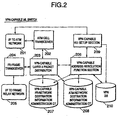
- Each of the VPN-capable ML switches 101-103 is composed of an ATM-network interface 201 to the ATM network 10
- the ATM-network interface 201 is connected to an ATM cell transceiver 202 which is capable of establishing a virtual channel and further transmits and receives ATM cells to and from the ATM network 10.
- a VPN-capable Layer-3 packet distributor 203 is connected to an FR frame transceiver 204 which is capable of establishing a virtual channel and further transmits and receives FR frames to and from the FR network connected to an FR-network interface 205.
- the VPN-capable Layer-3 packet distributor 203 performs the following functions using a VPN-capable address resolution function section 206, a VPN-capable FR-network destination information administration cache table (CT) 207 and a VPN-capable ATM-network destination information administration cache table (CT) 208.
- the VPN-capable Layer-3 packet distributor 203 performs the following functions:
- the VPN-capable address resolution function section 206 performs address resolution using the VPN-capable FR-network destination information administration cache table (CT) 207, the VPN-capable ATM-network administration cache table CT) 208, and a VPN database 210. More specifically, the VPN-capable address resolution function section 206 searches for the ATM address of a VPN-capable ML switch through which the Layer-3 packet is to leave the ATM network 10 based on the VPN-ID and the destination address of the Layer-3 packet. Further, the VPN-capable address resolution function section 206 performs the processing of a trigger message received from the VPN server 104.
- CT VPN-capable FR-network destination information administration cache table
- CT VPN-capable ATM-network administration cache table
- the VPN-capable address resolution function section 206 outputs the resolved ATM address to VPN-capable VCC setup section 209.
- the VPN-capable VCC setup section 209 uses the resolved ATM address inputted from the VPN-capable address resolution function section 206 to perform the establishment processing of a shortcut VCC for each VPN which is connected to the VPN-capable ML switch through which the Layer-3 packet is to leave the ATM network 10.
- the VPN-capable ATM--network administration cache table (CT) 208 retains the VPN-ID and the destination address of the Layer-3 packet as a search key and the resolved ATM address as searched data as will be described in detail later.
- the VPN-capable FR-network destination information administration cache table (CT) 207 retains the VPN-ID and the destination address of the Layer-3 packet as a search key and destination information including FR frame header and DLCI (Data Link Connection Identifier) as searched data, as will be described in detail later.
- CT FR frame header and DLCI
- the VPN server 104 has the following functions: 1) processing an address resolution request received from the VPN-capable ML switch for each VPN; 2) providing information to a VPN-capable ML witch for each VPN, wherein the information is required for the VPN-capable ML witch to transfer a packet received from the shortcut VCInto the FR network; 3) determining a next node to which a Layer-3 packet should be sent next depending on the VPN (routing); 4) forwarding the packet depending on the VPN (forwarding); 5) creating and retaining a routing table for each VPN; 6) retaining VPN information; 6) notifying the VPN information to a VPN-capable ML switch; and 7) instructing a VPN-capable ML switch to start address resolution processing.
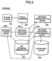
- the VPN server 104 is composed of an ATM-network interface 301 to the ATM network 10.
- the ATM-network interface 301 is connected to an ATM cell transceiver 302 which is capable of establishing a virtual channel and further transmits and receives ATM cells to and from the ATM network 10 under control of a VPN-capable Layer-3 packet distributor 303.
- the VPN-capable Layer-3 packet distributor 303 is further connected to a VPN trigger function section 304, a VPN-capable Layer-3 packet routing processing section 305, and a VPN-capable address resolution section 306.
- the VPN-capable Layer-3 packet distributor 303 has a conversion function of converting between ATM cells and FR frames, a VCC selection function of selecting a virtual channel connection depending on the VPN-ID and the destination address of a Layer-3 packet.
- the VPN trigger function section 304 has a function creating and transmitting a trigger message used for notification of VPN information and address resolution.
- the VPN-capable Layer-3 packet routing processing section 305 has a function of generating routing information of a Layer-3 packet for each VPN and a function of determining a next-hop node to which a packet should be forwarded next.
- the routing information for each VPN is stored onto a routing table 308.
- the VPN-capable address resolution function section 306 has a function of handling an address resolution request received from a VPN-capable ML switch for each VPN.
- the VPN-capable address resolution function section 306 further has a function of transmitting information including the FR frame header to a VPN-capable ML switch, wherein the information is required for the VPN-capable ML switch to handle a packet which has been received.
- a VPN information administration database 307 stores VPN information including VPN-ID and other information, which is used by the VPN trigger function section 304, the VPN-capable Layer-3 packet routing processing section 305, and the VPN-capable address resolution function section 306.
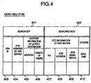
- the VPN-capable ATM-network administration cache table (CT) 208 consists of a search key field 401 and a searched data field 402.
- the search key field 401 consists of a VPN-ID field 403, a VPN server ATM address field 404, an address field 405 and a prefix length field 406 of the address information of Layer-3 destination.
- the searched data field 402 consists of a destination information field and another field.
- the VCC destination information field consists of a VCI field 407 for transmission VCC, an ATM address field 408 for the ATM address of VPN-capable ML switch connected to the transmission VCC at the opposite side, and QoS (Quality of Service) field 409 (for example, bandwidth) for the transmission VCC.
- the other field is a hold time field 410 for valid time period of the corresponding searched data.
- the VPN-capable FR-network destination information administration cache table (CT) 207 consists of a search key field 501 and a searched data field 502.
- the search key field 501 consists of a VPN-ID field 503, a source ATM address field 504 regarding the shortcut VCC, a destination ATM address 505, a destination address field 506 regarding the packet received through the shortcut VCC and a prefix length field 507 regarding the address information of Layer-3 destination.
- the searched data field 502 consists of an FR-network destination information field consisting of a DLCI field 507 regarding FR VCIdentifier, a physical port number field 509, and FR header field 510 regarding FR header to be added to a packet.
- a VCI field 520 may be used in place of the source ATM address field 504 and the destination ATM address 505 of Fig. 6.
- the system according to the present invention operates in VPN establishment phase, address resolution phase, and VPN data transfer phase.
- VPN establishment phase address resolution phase
- VPN data transfer phase an operation in the case of a plurality of VPN servers will be described.
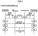
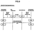
- the VPN server 602 stores VPN information onto the VPN information administration database 307 (step S701a).
- the VPN information includes the followings: a Layer-3 address of each user router participating in the virtual private network to be formed; a physical port, DLCI information, and ATM address information of a VPN-capable ML switch used by the user router: VCC information indicating how much bandwidth is needed for a certain virtual channel connection (VCC) for the VPN; and the VPN-ID.
- the VPN server 602 sets up a VCC for the VPN to each VPN-capable ML switch participating therein. Then, a pair of the VPN-ID and the VCI of the VCC registered onto the VPN information administration database 307. This causes the VPN server 104 to determine which VPN a received packet belongs to. Alternatively, the VPN server 104 instructs each VPN-capable ML switch participating therein to transfer a packet having VPN-ID added thereto on a specific VCC. This allows the VPN server 104 to determine which VPN a received packet belongs to.
- the contents of the VPN information administration database 307 are transferred to another VPN server 603 where the same database is formed (database synchronization). In the VPN server 603, as necessary, the same operation is performed (step S701b).
- the VPN server 104 transmits a VPN-VCC setup trigger message 702a, 702b to each VPN-capable ML switch participating therein.
- the VPN trigger function section 304 writes the following information to the VPN-VCC setup trigger message: the QoS information including VPN-ID and the bandwidth of a shortcut VCC for VPN; the ATM address of the VPN-capable ML switch connected by the VCC for VPN; and physical port and DLCI information of the VCC for a user router connected to the VPN-capable ML switch connected by the VCC for VPN.
- each of the VPN-capable ML switches 601 and 604 stores the VPN information conveyed in the VPN-VCC setup trigger message 704 onto the VPN database 210. Thereafter, each VPN-capable ML switch sets up a VCC having required QoS (bandwidth) to another VPN-capable ML switch which is an opposite side of the VCC to be set up (step S704). In this way, a shortcut VCC for VPN is set up.
- each VPN-capable ML switch After the shortcut VCC has been set up in the step S704, each VPN-capable ML switch performs a VCI verification step S705 by transferring the VPN-ID 706 through the setup shortcut VCC.
- each VPN-capable ML switch stores the received VPN-ID as well as the VCI through which the notice is transferred onto the VPN database 210 (step S707). In this manner, the VPN has been established.
- VPN-ID notification VCC setup processing step S708 using the signaling (709) in place of the steps S703 of Fig. 7.
- the VPN-ID obtained by the signaling is stored onto the VPN database 210 (step S710). In this manner, the VPN establishment phase may be performed.
- each user router exchanges a routing protocol packet used in routing protocol with the VPN server 104.
- the VPN-capable Layer-3 packet routing processing section 305 of the VPN server 104 computes routes for each VPN to produce the routing table 308 per VPN.
- the VPN server 104 transmits a route creation/change trigger to each VPN-capable ML switch (step S801).
- the route creation/change trigger conveys an address and a prefix length of Layer-3 destination.
- the VPN server 602 transmits a route creation/change triggers 802a and 802b to the VPN-capable ML switches 601 and 604, respectively.
- the address resolution processing S803 will be started.
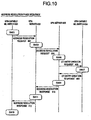
- the VPN-capable ML switch 601 in the step S901, produces an entry which is composed of the address and the prefix length of Layer-3 destination conveyed in the route creation/change trigger and is further composed of the ATM address of the VPN server 602 which has transmitted the trigger thereto and the VPN-ID. Then, the entry is stored as a key onto the VPN-capable ATM-network administration cache table (CT) 208. Thereafter, the VPN-capable ML switch 601 outputs a notice including the address and the prefix length of Layer-3 destination and VPN-ID to the VPN-capable address resolution function section 206. When receiving the notice, the VPN-capable address resolution function section 206 produces an address resolution request message 902 and outputs it to the VPN server 602.
- CT VPN-capable ATM-network administration cache table
- the VPN server 602 When receiving the address resolution request message 902 from the VPN-capable ML switch 601, the VPN server 602 performs the step S903.
- the VPN-ID is extracted from the received request message 902 and the VPN-capable Layer-3 packet routing processing section 305 and the routing table 308 are used to determine the next hop node address to which the message 902 should be sent next.
- the next hop node address, the VPN-ID, and the request message 902 are transferred to the VPN-capable address resolution section 306.
- the VPN-capable address resolution section 306 determines whether the next hop node is a VPN server or a user router to be connected via a VPN-capable ML switch.
- the next hop node is the VPN server 603. Therefore, the address resolution request message 904 is transferred to the VPN server 603.
- the VPN server 603 When receiving the address resolution request message 904 fro the VPN server 602, the VPN server 603 performs the step S905. In the step S905, the VPN server 603 determines the next hop node destination to which the received reguest message 904 should be forwarded next in the VPN. Here, since the next hop node is a user router to be connected via the VPN-capable ML switch 604, the VPN server 603 performs the transmission processing of a CT entry creation reguest message 906.
- the CT entry creation request message 906 is produced by using the VPN-capable address resolution section 306 to add the Layer-2 packet header information attached in the VPN-capable Layer-3 packet distributor 303 to the address resolution request message 904. Then, the CT entry creation request message 906 is transmitted to the VPN-capable ML switch 604, which is a transit node.
- the VPN-capable ML switch server 604 When receiving the address resolution request message 906 from the VPN server 603, the VPN-capable ML switch server 604 performs the step S907.
- the ATM cell transceiver 202 transfers the received message 906 to the VPN-capable Layer-3 packet distributor 203 Since it is a CT entry creation request message, it is transferred to the VPN-capable address resolution function section 206.
- the VPN-capable address resolution function section 206 produces an entry which is composed of the address, the prefix length, and the source ATM address conveyed in the CT entry creation request message and the ATM address of the self node. Then, the entry is stored as a key onto the VPN-capable FR-network administration cache table (CT) 207. Further, the VPN-capable address resolution function section 206 writes information onto the DLCI field 508, the physical port field 509 and the FR header field 510 based on the Layer-2 packet header information conveyed in the CT entry creation request message 906.
- CT VPN-capable FR-network administration cache table
- the VPN-capable ML switch server 604 produces a CT entry creation response message 908 by adding the ATM address of its own as the destination ATM address to the CT entry creation request message 906.
- the CT entry creation response message 908 is transmitted to the VPN server 603.
- the VPN server 603 When receiving the CT entry creation response message 908, the VPN server 603 performs the step S909. In the step S909, the VPN-ID, the address and the prefix length of the Layer-3 destination, and the destination ATM address are extracted from the CT entry creation response message 908 and they are written onto an address resolution response message 910, which is transmitted to the VPN server 602.
- the VPN server 602 When receiving the address resolution response message 910, the VPN server 602 performs the stop S911 where the received address resolution response message 910 is transferred as an address resolution response message 912 to the VPN-capable ML switch 601.
- the VPN-capable ML switch 601 When receiving the address resolution response message 912, the VPN-capable ML switch 601 performs the step S913.
- the VPN database 210 is searched for VCC information for the VPN using as a key the destination ATM address and the VPN-ID conveyed in the address resolution response message 912.
- the obtained VCC information is stored onto the destination VCC information field of the entry produced by the step S901 in the VPN-capable ATM-network administration cache table (CT) 208 (see Fig. 4).
- CT VPN-capable ATM-network administration cache table
- the hold time of the entry is usually infinite. In the case where the contents of entries are checked at regular intervals, the check time interval is stored onto the bold time field.
- the address resolution phase is completed and data transfer is allowed over the VPN, that is, the VPN data transfer phase is started.
- a VCC for each VPN or VPN-ID is added to a routing protocol packet and the routing protocol packet is transmitted through a specific VCC to the VPC server 104
- the routing protocol packet is used to produce the per-VPN routing table 308.
- the VPN-capable ATM-network administration cache table (CT) 208 is searched using the VPN-ID and the destination address of Layer 3 as a key. If an entry is found, a shortcut VCC is specified by the VCI obtained by the found entry. The shortcut VCC is used to transfer the packet to another VPN-capable ML switch which is an opposite side of the shortcut VCC.
- the VPN-capable ML searches the VPN database 210 for VPN-ID using the VCI of the shortcut VCC as a key. Thereafter, the VPN-capable FR-network destination information administration CT 207 is searched using the found VPN-ID, the source ATM address, the self ATM address, and the destination address of the received packet. If an entry is found in the VPN-capable FR-network destination information administration CT 207, the found entry has FR header information which is to be added to the received packet. Based on the header information, an FR frame is formed and is transmitted to the DLCI of the physical port obtained by the found entry. In this way, the data transfer phase is completed.
- the VPN server monitors the contents of a routing table for each VPN.
- the VPN server transmits a route creation/change trigger to all the VPN-capable ML switches associated with the VPN that has changed in the routing table.
- the VPN-capable ML switches which have received the route creation/change trigger starts the address resolution phase as described in Fig. 9.
- the VPN-capable FR-network destination information administration CT 207 and the VPN-capable ATM-network destination information administration CT 208 which are associated with each shortcut VCC are updated depending on the changed routing table.
- the present invention may be applied to the MPOA system as described before, which has a network configuration similar to that of Fig. 1. More specifically, a VPN-capable MPOA server and a VPN-capable MPOA ML switch are provided in place of the VPN server 104 and the VPN-capable ML switch, respectively.
- the MPOA server has the VPN information administration database 307 (see Fig. 3) added thereto. Further, the processing of the Layer-3 packet distributor, MPOA trigger function section, Layer-3 packet routing processor and routing table is changed such that it is performed for each VPN which has been set in the VPN information administration database 307. Further, the MPOS trigger function section has an additional function of notifying each MPOA ML switch registered in the VPN information administration database 307 of information indicating between which MPOA ML switches registered in the VPN information administration database 307 a VCC for the VPN is set up, the quality information required for the VCC for the VPN, VPN-ID, and the like. The above-mentioned addition allows the MPOA server to perform the same functions as the VPN server used in the embodiment as described above.
- the VPN-capable MPOA ML switch may be formed based on the conventional MPOA ML switch as described before. More specifically, the VPN-ID field as a search key is added to an MPOA ATM-network destination information administration cache table.
- Such a VPN-capable MPOA ATM-network destination information administration cache table can operate in the same manner as the VPN-capable ATM-network destination information administration cache table (CT) 208.
- CT VPN-capable ATM-network destination information administration cache table
- the VPN-ID field as a search key and the QoS field as the destination VCC information are added to an MPOA FR-network destination information administration cache table.
- Such a VPN-capable MPOA FR-network destination information administration cache table can operate in the same manner as the VPN-capable FR-network destination information administration cache table (CT) 207.
- CT VPN-capable FR-network destination information administration cache table
- the MPOA VCC setup section is changed to the VPN-capable VCC setup section 209 which is capable of receiving a notice of VPN information from the MPOA server and further of setting VCC for each VPN.
- the VPN database 210 is added. Such a configuration allows the MPOA ML switch to retain VPN information.
- the MPOA address resolution function section has the following functions added thereto: 1) transmitting an address resolution request having the VPN-ID attached thereto based on the retained VPN information; and 2) retaining the destination ATM address information and the FR network destination information obtained by the address resolution request for each VPN onto the MPOA FR-network destination information administration cache table and the MPOA ATM-network destination information administration cache table which have had the VPN-ID field added thereto.
- the above-mentioned addition allows the MPOA ML switch to perform the same functions as the VPN-capable ML switch used in the embodiment as described above.
Landscapes
- Engineering & Computer Science (AREA)
- Computer Networks & Wireless Communication (AREA)
- Data Exchanges In Wide-Area Networks (AREA)
Applications Claiming Priority (2)
| Application Number | Priority Date | Filing Date | Title |
|---|---|---|---|
| JP8094798 | 1998-03-27 | ||
| JP08094798A JP3384319B2 (ja) | 1998-03-27 | 1998-03-27 | 仮想専用網構築システム |
Publications (2)
| Publication Number | Publication Date |
|---|---|
| EP0952755A2 true EP0952755A2 (fr) | 1999-10-27 |
| EP0952755A3 EP0952755A3 (fr) | 2003-04-09 |
Family
ID=13732703
Family Applications (1)
| Application Number | Title | Priority Date | Filing Date |
|---|---|---|---|
| EP19990250096 Withdrawn EP0952755A3 (fr) | 1998-03-27 | 1999-03-27 | Méthode et dispositif pour former un réseau privé virtuel |
Country Status (3)
| Country | Link |
|---|---|
| EP (1) | EP0952755A3 (fr) |
| JP (1) | JP3384319B2 (fr) |
| CA (1) | CA2267033A1 (fr) |
Cited By (10)
| Publication number | Priority date | Publication date | Assignee | Title |
|---|---|---|---|---|
| WO2001097460A1 (fr) * | 2000-06-14 | 2001-12-20 | Nortel Networks Ltd. | Routeur de commutation d'etiquettes distribue |
| WO2001099354A1 (fr) * | 2000-06-16 | 2001-12-27 | Fujitsu Limited | Dispositif de communication comprenant une fonction d'amenagement vpn |
| EP1331766A1 (fr) * | 2001-12-20 | 2003-07-30 | Alcatel | Telekommunikationssystem mit einer Architektur von virtuellem Dienst-Netzwerk |
| EP1100232A3 (fr) * | 1999-11-10 | 2004-03-17 | Nortel Networks Limited | Système procédé et dispositif pour la atribution de canaux virtuels dans un réseau de communications |
| US6947428B1 (en) | 2000-06-14 | 2005-09-20 | Nortel Networks Limited | Distributed label switching router |
| US7054319B2 (en) | 2000-06-02 | 2006-05-30 | Hitachi, Ltd. | VPN router and VPN identification method by using logical channel identifiers |
| KR100621735B1 (ko) * | 1999-12-22 | 2006-09-06 | 주식회사 케이티 | 데이터통신망의 가상사설망 서비스 구현을 위한 통신서비스세션관리방법 |
| CN100385865C (zh) * | 1999-12-27 | 2008-04-30 | 日本电气株式会社 | 使用ip-vpn功能的atm边缘节点交换设备 |
| US7908350B2 (en) * | 2005-12-13 | 2011-03-15 | International Business Machines Corporation | Methods for operating virtual networks, data network system, computer program and computer program product |
| CN103152238A (zh) * | 2002-07-17 | 2013-06-12 | 北电网络有限公司 | 运营商的运营商vpn环境中的分层光纤vpn |
Families Citing this family (5)
| Publication number | Priority date | Publication date | Assignee | Title |
|---|---|---|---|---|
| KR100454980B1 (ko) * | 2000-11-13 | 2004-11-08 | 주식회사 다산네트웍스 | 가상 드라이버를 이용한 라우터 및 라우팅방법 |
| CN100477628C (zh) | 2003-05-16 | 2009-04-08 | 富士通株式会社 | 通过多层进行通信的通信网中的路径设定方法和通信装置 |
| JP4535122B2 (ja) * | 2007-12-27 | 2010-09-01 | 株式会社日立製作所 | データ転送装置、方法及びシステム |
| CN106911532B (zh) * | 2017-02-07 | 2020-04-10 | 佛山易识科技有限公司 | 基于虚拟可扩展局域网的多虚拟通道智能选路方法 |
| JP7794322B2 (ja) * | 2022-08-19 | 2026-01-06 | Ntt株式会社 | 通信システム、通信方法および通信プログラム |
Family Cites Families (2)
| Publication number | Priority date | Publication date | Assignee | Title |
|---|---|---|---|---|
| US5768271A (en) * | 1996-04-12 | 1998-06-16 | Alcatel Data Networks Inc. | Virtual private network |
| US6081524A (en) * | 1997-07-03 | 2000-06-27 | At&T Corp. | Frame relay switched data service |
-
1998
- 1998-03-27 JP JP08094798A patent/JP3384319B2/ja not_active Expired - Fee Related
-
1999
- 1999-03-26 CA CA 2267033 patent/CA2267033A1/fr not_active Abandoned
- 1999-03-27 EP EP19990250096 patent/EP0952755A3/fr not_active Withdrawn
Cited By (13)
| Publication number | Priority date | Publication date | Assignee | Title |
|---|---|---|---|---|
| EP1100232A3 (fr) * | 1999-11-10 | 2004-03-17 | Nortel Networks Limited | Système procédé et dispositif pour la atribution de canaux virtuels dans un réseau de communications |
| KR100621735B1 (ko) * | 1999-12-22 | 2006-09-06 | 주식회사 케이티 | 데이터통신망의 가상사설망 서비스 구현을 위한 통신서비스세션관리방법 |
| CN100385865C (zh) * | 1999-12-27 | 2008-04-30 | 日本电气株式会社 | 使用ip-vpn功能的atm边缘节点交换设备 |
| US7054319B2 (en) | 2000-06-02 | 2006-05-30 | Hitachi, Ltd. | VPN router and VPN identification method by using logical channel identifiers |
| US6947428B1 (en) | 2000-06-14 | 2005-09-20 | Nortel Networks Limited | Distributed label switching router |
| WO2001097460A1 (fr) * | 2000-06-14 | 2001-12-20 | Nortel Networks Ltd. | Routeur de commutation d'etiquettes distribue |
| WO2001099354A1 (fr) * | 2000-06-16 | 2001-12-27 | Fujitsu Limited | Dispositif de communication comprenant une fonction d'amenagement vpn |
| US8423669B2 (en) | 2000-06-16 | 2013-04-16 | Fujitsu Limited | Communication device having VPN accommodation function |
| US8489767B2 (en) | 2000-06-16 | 2013-07-16 | Fujitsu Limited | Communication device having VPN accommodation function |
| US9413657B2 (en) | 2000-06-16 | 2016-08-09 | Fujitsu Limited | Communication device having VPN accommodation function |
| EP1331766A1 (fr) * | 2001-12-20 | 2003-07-30 | Alcatel | Telekommunikationssystem mit einer Architektur von virtuellem Dienst-Netzwerk |
| CN103152238A (zh) * | 2002-07-17 | 2013-06-12 | 北电网络有限公司 | 运营商的运营商vpn环境中的分层光纤vpn |
| US7908350B2 (en) * | 2005-12-13 | 2011-03-15 | International Business Machines Corporation | Methods for operating virtual networks, data network system, computer program and computer program product |
Also Published As
| Publication number | Publication date |
|---|---|
| JPH11284664A (ja) | 1999-10-15 |
| EP0952755A3 (fr) | 2003-04-09 |
| JP3384319B2 (ja) | 2003-03-10 |
| CA2267033A1 (fr) | 1999-09-27 |
Similar Documents
| Publication | Publication Date | Title |
|---|---|---|
| US6636516B1 (en) | QOS-based virtual private network using ATM-based internet virtual connections | |
| US6683874B1 (en) | Router device and label switched path control method using upstream initiated aggregation | |
| US7197033B2 (en) | System and method for establishing a communication path associated with an MPLS implementation on an ATM platform | |
| US6343322B2 (en) | IP over ATM system using control messages to set up cut-through paths or bypass pipes in routers | |
| JP2656696B2 (ja) | データメッセージ転送方法及び装置 | |
| US7088717B2 (en) | System and method of operating a communication network associated with an MPLS implementation of an ATM platform | |
| JP4094658B2 (ja) | フラッディング抑制方法 | |
| US8018939B2 (en) | MPLS implementation of an ATM platform | |
| JPH1075258A (ja) | Lan間接続方法 | |
| JPH10215263A (ja) | 通信ネットワークおよび通信確立方法 | |
| US6643289B1 (en) | Method of MPOA status change notification | |
| CA2267033A1 (fr) | Systeme et methode de formation d'un reseau prive virtuel | |
| US6781952B2 (en) | Establishment of designated S-PVC connection in PNNI operation ATM switching apparatus network | |
| US20010025319A1 (en) | Routing information mapping device in a network, method thereof and storage medium | |
| JPH1168755A (ja) | Atm網のブロードキャスト制御システム並びにネットワーク装置及び交換ノード装置 | |
| US6606321B1 (en) | Method of establishing MPOA shortcut virtual channel connections | |
| JPH06296177A (ja) | 複合通信網 | |
| CA2341939C (fr) | Methode de transmission de paquets avec demande d'etiquette, methode et reseau de transfert de paquets et dispositifs de transfert de paquets | |
| US6822962B1 (en) | Virtual connection switching method and ATM switch | |
| US6947423B2 (en) | MAC address notification method in MPOA systems and MPOA server for the same | |
| JP3052924B2 (ja) | ショートカットルート確立システムおよびデータフロー検出装置 | |
| JPH11261567A (ja) | パケット転送装置 | |
| JP3069842B2 (ja) | フレームの高速転送方式 | |
| JPH11215157A (ja) | パケット交換機及び管理セル中継方法 | |
| JPH05219095A (ja) | Atm交換システムにおけるグループ通信方式 |
Legal Events
| Date | Code | Title | Description |
|---|---|---|---|
| PUAI | Public reference made under article 153(3) epc to a published international application that has entered the european phase |
Free format text: ORIGINAL CODE: 0009012 |
|
| AK | Designated contracting states |
Kind code of ref document: A2 Designated state(s): AT BE CH CY DE DK ES FI FR GB GR IE IT LI LU MC NL PT SE |
|
| AX | Request for extension of the european patent |
Free format text: AL;LT;LV;MK;RO;SI |
|
| PUAL | Search report despatched |
Free format text: ORIGINAL CODE: 0009013 |
|
| AK | Designated contracting states |
Kind code of ref document: A3 Designated state(s): AT BE CH CY DE DK ES FI FR GB GR IE IT LI LU MC NL PT SE Designated state(s): AT BE CH CY DE DK ES FI FR GB GR IE IT LI LU MC NL PT SE |
|
| AX | Request for extension of the european patent |
Extension state: AL LT LV MK RO SI |
|
| 17P | Request for examination filed |
Effective date: 20030417 |
|
| 17Q | First examination report despatched |
Effective date: 20030610 |
|
| AKX | Designation fees paid |
Designated state(s): DE GB |
|
| STAA | Information on the status of an ep patent application or granted ep patent |
Free format text: STATUS: THE APPLICATION IS DEEMED TO BE WITHDRAWN |
|
| 18D | Application deemed to be withdrawn |
Effective date: 20031021 |