EP0953408B1 - Support et appareil de polissage - Google Patents
Support et appareil de polissage Download PDFInfo
- Publication number
- EP0953408B1 EP0953408B1 EP99105190A EP99105190A EP0953408B1 EP 0953408 B1 EP0953408 B1 EP 0953408B1 EP 99105190 A EP99105190 A EP 99105190A EP 99105190 A EP99105190 A EP 99105190A EP 0953408 B1 EP0953408 B1 EP 0953408B1
- Authority
- EP
- European Patent Office
- Prior art keywords
- sheet
- carrier
- pressure chamber
- holes
- portions
- Prior art date
- Legal status (The legal status is an assumption and is not a legal conclusion. Google has not performed a legal analysis and makes no representation as to the accuracy of the status listed.)
- Expired - Lifetime
Links
Images





Classifications
-
- B—PERFORMING OPERATIONS; TRANSPORTING
- B24—GRINDING; POLISHING
- B24B—MACHINES, DEVICES, OR PROCESSES FOR GRINDING OR POLISHING; DRESSING OR CONDITIONING OF ABRADING SURFACES; FEEDING OF GRINDING, POLISHING, OR LAPPING AGENTS
- B24B37/00—Lapping machines or devices; Accessories
- B24B37/27—Work carriers
- B24B37/30—Work carriers for single side lapping of plane surfaces
-
- H—ELECTRICITY
- H10—SEMICONDUCTOR DEVICES; ELECTRIC SOLID-STATE DEVICES NOT OTHERWISE PROVIDED FOR
- H10P—GENERIC PROCESSES OR APPARATUS FOR THE MANUFACTURE OR TREATMENT OF DEVICES COVERED BY CLASS H10
- H10P52/00—Grinding, lapping or polishing of wafers, substrates or parts of devices
Definitions
- the present invention relates to a carrier capable of picking up, pressing, and releasing a wafer or other workpiece, as per the preamble of claim 1.
- a carrier capable of picking up, pressing, and releasing a wafer or other workpiece, as per the preamble of claim 1.
- An example of such a carrier is disclosed by JP 2 243 263 A.
- FIG. 17 is a sectional view of a carrier of the related art.
- a carrier 100 is comprised of a housing 101, a carrier base 103 attached to the bottom surface of the housing 101 and having a backing sheet 102 at its bottom surface, and a retainer ring 104 attached to the outer periphery of the bottom surface of the carrier base 103.
- the carrier 100 is further formed with a plurality of air holes 106 passing through the backing sheet 102 and carrier base 103 and communicating with grooves 105 of the housing 101 at their upper ends, and an air exit/inlet communicating with the grooves 105.
- the wafer W may be picked up by making the insides of the air holes 106 a negative pressure state.
- the negative pressure state inside the air holes 106 is released and the wafer W polished while pressing the wafer W by the carrier base 103 against a polishing pad 111 of a rotating platen 110. Further, by supplying water at a predetermined pressure into the air holes 106, the polished wafer W can be released from the backing sheet 102.
- a carrier 300 provides a ring-shaped projecting portion 302 at the outer peripheral portion of the bottom surface of a carrier base 301.
- a pressure chamber 303 is defined.
- a retainer ring 304 is adhered by a double-sided adhesive tape 308 at the outer peripheral portion of the bottom surface of the film 305, that is, to a position corresponding to the projecting portion 302.
- the film 305 would deform to match the shape of the back surface of the wafer W. Further, the entire surface of the wafer W was pressed by a uniform air pressure. Therefore, it was possible to polish the surface of the wafer W to a high precision.
- the wafer W Since the air in the pressure chamber 303 escaped to the outside from the holes 305a in the film 305 and then along the upper surface of the wafer W, however, the wafer W was contaminated, i.e., so-called leak contamination occurred. Further, the polishing solution entering between the retainer ring 304 and the wafer W was dried by the air escaping from the holes 305a resulting in abrasive becoming affixed on the inner peripheral surface of the retainer ring 304. Therefore, clumps of abrasive could peel off during polishing and scratch the wafer W.
- An object of the present invention is to provide a carrier and polishing apparatus which enables high precision polishing of a workpiece and enables prevention of leak contamination or damage to the workpiece.
- a carrier comprising: a carrier body having a workpiece holding hole; a pressure chamber defined by a pliable sheet laid in the holding hole of the carrier body and capable of contacting the entire back surface of a workpiece; a fluid passage portion formed by a fluid path provided in the carrier body and communicating with the pressure chamber and by a plurality of holes provided in the sheet and communicating with the pressure chamber; wherein valve portions are provided near the holes of the sheets for closing the holes when the inside of the pressure chamber is a positive pressure in state and opening the holes when the pressure chamber is a negative pressure in state.
- valve portions can be provided with floats which float up in a fluid filled in the pressure chamber to make the valve portions operate to open the holes.
- valve portions need only be configured to close the holes when the inside of the pressure chamber is a negative pressure state and to open the holes when the inside of the pressure chamber is a positive pressure state. Therefore, as one example, the valve portions are formed by pliable plate-shaped members with one ends attached to the sheet in a state with the other ends covering the holes of the sheet from the pressure chamber side.
- the pressure chamber sides of the plate-shaped members are provided with floats which float up in a fluid filled in the pressure chamber.
- the sheet is comprised of n number of sheet members having pliability laminated and adhered to each other; a plurality of valve portions are formed by a plurality of nonadhered portions provided between an x (1 ⁇ x ⁇ n)-th sheet member and an x+1-th sheet member from the pressure chamber side; and the holes are comprised of first through holes passing through the sheet members up to the x-th sheet member and opening to one end part of the nonadhered portions and second through holes communicating with the other end parts of the nonadhered portions and passing through the n-th sheet member from the x+1-th sheet member.
- the fluid in the second through holes is sucked out from the first through holes to the pressure chamber side through the nonadhered portions and the workpiece is picked up by suction by the n-th sheet member.
- the fluid pressure in the pressure chamber causes the x-th sheet member to press against the x+1-th sheet member and close the nonadhered portions.
- the fluid in the pressure chamber will flow out to the wafer W side through the first through holes, the nonadhered portions, and the second through holes and the workpiece will be automatically released.
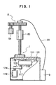
- FIG. 1 is a partially cutaway front view of a CMP apparatus according to a first embodiment of the present invention.
- this CMP apparatus is provided with a platen 110 having a polishing pad 111 attached to its surface, a carrier 1, a rotary drive mechanism 8 serving as the rotary drive means, and an air pump 9 serving as a fluid supply means.
- the platen 110 is designed to be driven to rotate by a main motor 112 disposed inside the apparatus housing.
- a belt 118 is wound around a pulley 114 attached to the main motor 112 and a pulley 117 attached to an input shaft 116 of a transmission 115.
- the platen 110 is attached to an output shaft 119 of the transmission 115.
- the rotation of the main motor 112 is transmitted to the pulley 117, the rotation of the pulley 117 is converted in speed by the transmission 115 and transmitted to the output shaft 119, and the platen 110 is rotated at a predetermined speed.
- the rotary drive mechanism 8 is a mechanism for making the carrier 1 rotate while pressing against it and is provided with a cylinder 80 and a motor 84.
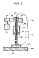
- FIG. 2 is a sectional view of the rotary drive mechanism 8.
- the cylinder 80 is comprised of a piston rod 82 passing through a cylinder body 81 and a piston 83 air-tightly fitting in the cylinder body 81 in a state affixed to the outer side of the piston rod 82.
- the motor 84 is linked with the piston rod 82 of the cylinder 80. That is, a gear 85 of the shaft of the motor 84 is engaged with a gear 87 attached through a bearing 86 at the upper portion of the piston rod 82.
- the upper end of the cylindrical inner rod 89 is affixed to a support member 88 affixed to the upper surface of the gear 87.
- the carrier 1 is structured to be able to rotate in a state where the wafer W on the polishing pad 111 of the platen 110 is held and is attached to the lower end portion of the piston rod 82.
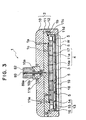
- FIG. 3 is a sectional view of the structure of the carrier 1.
- the carrier 1 is provided with a carrier body 2, a pressure chamber 3, and a fluid passage portion 4.
- a plurality of valve portions 5 are specially provided inside the pressure chamber 3.
- the carrier body 2 is comprised of a housing 10, a carrier base 11, and a retainer ring 12.
- the housing 10 has a rotatable connecting member 10a at its center portion.
- the lower end portion of the piston rod 82 is connected to this connecting member 10a.
- this housing 10 has an internal gear 10b at the bottom side of the connecting member 10a.
- the internal gear 10b engages with an external gear 89a formed at the lower end side of the inner rod 89 passing through a center hole of the connecting member 10a.
- the carrier base 11 is affixed by screws 1a to the bottom surface of the housing 10.
- the retainer ring 12 is attached to the bottom side of the outer peripheral portion of the carrier base 11.
- a depression 11c of the same width as the retainer ring 12 is cut into the bottom surface of the outer peripheral portion of the carrier base 11.
- the retainer ring 12 is affixed by screws 1b in a state with the top part of the retainer ring 12 fit into the depression 11c.
- An O-ring 11d is fit between the retainer ring 12 and the carrier base 11 so as to hold the air-tight state.
- a wafer holding hole S is defined at the inside of the retainer ring 12.
- the pressure chamber 3 is defined by the sheet supporter 13 and the two-layer sheet comprised of the hard sheet 18 and the soft backing sheet 19.
- the sheet supporter 13 is affixed by screws 1c to the bottom surface of the carrier base 11 in a state arranged in the holding hole S for holding the wafer W.
- This sheet supporter 13 is comprised of a supporter body 14 affixed by screws 1c to the bottom surface of the carrier base 11, a diaphragm 15 having pliability, and an edge ring 16 formed in a ring shape along the outer edge portion of the diaphragm 15.
- the hard sheet 18 and the soft backing sheet 19 are bonded together in the state with the hard sheet 18 at the top.
- the outer peripheral portion of the upper hard sheet 18 is affixed air-tightly to the bottom surface of the edge ring 16.
- a pressure chamber 3 is defined between the hard sheet 18 and the sheet supporter 13.
- the fluid passage portion 4 is comprised of a fluid path formed in the carrier base 11 and sheet supporter 13 and a plurality of holes 17 formed in the hard sheet 18 and the soft backing sheet 19.
- shallow grooves 11a are cut into the bottom surface of the carrier base 11.
- an air exit/inlet 11b for exit and entry of air of a later mentioned air pump 9.
- a plurality of air holes 14a are formed in the supporter body 14. These air holes 14a communicate with the air exit/inlet 11b through the grooves 11a.
- a fluid path communicating with the pressure chamber 3 is comprised by the air holes 14a, the grooves 11a, and the air exit/inlet 11b.
- an O-ring lie is fit at the outside of the grooves 11a, whereby the airtightness between the carrier base 11 and the supporter body 14 is held and air inside the grooves 11a is prevented from leaking to the outside.
- the holes 17 pass through the hard sheet 18 and the soft backing sheet 19 and communicate with the fluid path through the pressure chamber 3.
- the valve portions are portions for opening and closing the holes 17.
- FIG. 4 is a perspective view of a valve portion 5
- FIG. 5 is a partially enlarged sectional view showing the state of attachment of a valve portion 5
- FIG. 6 is a plane view of a plurality of valve portions 5.
- a valve portion 5, as shown in FIG. 4, is a pliable plate-shaped member formed by a plastic etc. and is provided with a notch 50 across its widthwise direction.
- valve portion 5 is divided into an opening/closing portion 51 and an attaching portion 52 by this notch 50.
- the size of the opening/closing portion 51 is set to be larger than the opening of a hole 17 of the hard sheet 18 and the soft backing sheet 19.
- Such a valve portion 5, as shown in FIG. 5 and FIG. 6, is placed on the hard sheet 18 with the notch 50 side down in a state with the opening/closing portion 51 covering the opening of a hole 17.
- the attaching portion 52 is attached to the hard sheet 18 by an adhesive.
- valve portion 5 Since the valve portion 5 is provided with the notch 50 and therefore the connecting portion of the opening/closing portion 51 and the attaching portion 52 becomes thinner, when the inside of the pressure chamber 3 becomes a negative pressure state, the opening/closing portion 51 will bend at the notch 50 to open the hole 17 as shown by the broken lines in FIG. 5. Further, when the inside of the pressure chamber 3 becomes a positive pressure, the opening/closing portion 51 will be pressured against the hard sheet 18 to close the hole 17 as shown by the solid lines.
- the air pump 9 shown in FIG. 1 and FIG. 2 is a device which supplies air of a desired pressure into the above pressure chamber 3 to make the inside of the pressure chamber 3 a positive pressure or sucks air inside of the pressure chamber 3 out to make the inside of the pressure chamber R a negative pressure.
- an air hose 90 is inserted through the inner rod 89 and as shown in FIG. 3 has a front end portion fit into the air exit/inlet 11b of the carrier base 11.
- FIG. 7 7 is a schematic overall view of a polishing system using a CMP apparatus of this embodiment.
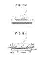
- FIGS. 8A to 8D are views schematically showing a transferring-in step, polishing step, and transferring-out step of the wafer W. Therefore, in FIGS. 8A to 8C, the housing 10, carrier base 11, retainer ring 12, and sheet supporter 13 are omitted and only the carrier body 2, pressure chamber 3, a valve portion 5, hard sheet 18, soft backing sheet 19, a hole 17, and wafer W are shown.
- the air pump 9 shown in FIG. 1 and FIG. 2 is driven to suck air at the point of time when the wafer W contacts the soft backing sheet 19.
- the pressure chamber 3 becomes a negative pressure state and the opening/closing portion 51 of the valve portion 5 bends to open the hole 17. As a result, air inside the hole 17 is sucked out and the wafer W is sucked against the soft backing sheet 19 through the hole 17.
- the carrier 1 is made to rise by the cylinder 80.
- the wafer W is transferred directly above the platen 110 of the CMP apparatus, then the carrier 1 is made to descend by the cylinder 80 until the wafer W contacts the polishing pad 111, then the wafer is pressed against the polishing pad 111 by a predetermined pressing force.
- the air pump 9 is driven to supply air and sends air from the air hose 90 through the fluid path of the fluid passage portion 4 into the pressure chamber 3.
- the inside of the pressure chamber 3 becomes a positive pressure in state and the opening/closing portion 51 of the valve portion 5 is pressed against the hard sheet 18 to close the hole 17.
- the hard sheet 18 and soft backing sheet 19 deform molding against the unevenness of the back surface of the wafer W and a uniform air pressure P is applied to substantially the entire upper surface of the wafer W.
- the motors 84 and 112 are driven to make the carrier 1 and the platen 110 rotate while supplying a not shown polishing solution, whereby the surface of the wafer is flattened by a high precision by the polishing pad 111.
- the inside of the pressure chamber 3 is made a negative pressure state and the carrier 1 is made to rise while holding the wafer W by suction.
- the entire assembly is then transferred directly above the transferring-out table 62.
- the carrier 1 is made to descend. The descent of the carrier 1 is stopped at the point of time when the wafer W is positioned very close to the transferring-out table 62.
- FIG. 10 is a partially enlarged sectional view of the essential portions of a CMP apparatus according to a second embodiment of the present invention.
- This embodiment differs from the above first embodiment in the point that the release operation of the wafer W is automatically performed.
- a float 53 is attached to the upper surface of the opening/closing portion 51 of each of the valve portions 5.
- This float 53 is formed by a material having a smaller specific gravity than even water, such as polystyrene foam.
- FIG. 11 is a partially enlarged sectional view of the essential portions of a CMP apparatus according to a third embodiment of the present invention.
- This embodiment differs from the first and second embodiments in the point of forming the valve portions utilizing the gap between the hard sheet 18 and the soft backing sheet 19 and without using any special valve portions 5 such as in the first and second embodiments.
- the above embodiments were structured with the entire bottom surface of the hard sheet 18 and the entire top surface of the soft backing sheet 19 adhered together by an adhesive.
- nonadhered portions D with no adhesive 98 are formed between the hard sheet 18 and the soft backing sheet 19.
- holes 17 passing straight through the hard sheet 18 and soft backing sheet 19 like in the above embodiments are not used. Instead, as shown in FIG. 12 as well, provision is made of first through holes 17a passing through the hard sheet 18 and communicating with one end part (right end part in FIG. 11 and FIG. 12) of a nonadhered portion D and second through holes 17b communicating with the other end part (left end part in FIG. 11 and FIG. 12) of the nonadhered portion D and passing through the soft backing sheet 19.
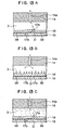
- FIGS. 13A to 13C are partially enlarged sectional views showing the operations for picking up, pressing, and releasing a wafer.
- valve portions are formed by the nonadhered portions D of the hard sheet 18 and soft backing sheet 19, it is possible to further reduce the number of parts and the cost of the product.
- air was used as the fluid, but it is also possible to use a fluid such as oil and press uniformly against the wafer W by oil pressure etc.
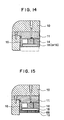
- a double-layer structure sheet comprised of the hard sheet 18 and the soft backing sheet 19 was used, but as shown in FIG. 14, it is also possible to arrange either of the hard sheet 18 or soft backing sheet 19 at the bottom surface of the edge ring 16 and affix the outer peripheral portion of the upper surface of the hard sheet 18 or soft backing sheet 19 air-tightly to the edge ring 16 and attach the valve portions 5 to the upper surface of the hard sheet 18 or soft backing sheet 19.
- the hard sheet 18 and the soft backing sheet 19 may be adhered together by an intermediate sheet 89 such as a double-sided adhesive tape and the outer peripheral portion of the upper surface of the hard sheet 18 be affixed air-tightly to the edge ring 16.
- an intermediate sheet 89 such as a double-sided adhesive tape
- the outer peripheral portion of the upper surface of the hard sheet 18 be affixed air-tightly to the edge ring 16.
- cutaway portions of the shape shown by the broken lines in FIG. 12 in the intermediate sheet 89 to form the nonadhered portions D shown in the third embodiment.
- the pressure chamber 3 was defined by the sheet supporter 13, hard sheet 18, and soft backing sheet 19, but it is of course also possible not to use the sheet supporter 13 and, as in the carrier of the related art shown in FIG. 18, attach the hard sheet 18 and the soft backing sheet 19 to the retainer ring 12 to define the pressure chamber 3.
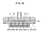
- FIG. 16 As a modification of the carrier of the related art shown in FIG. 18, there is one of the structure shown in FIG. 16.
- This carrier was structured with a pressure plate 400 having a backing sheet affixed to a film 305 adhered to the outer peripheral portion of the bottom surface of a carrier base 301 and with a retainer ring 304 attached to the outer periphery of this pressure plate 400.
- valve portions 5 with floats 53 to the film 305 and forming holes 400a communicating with the holes 305a in the pressure plate 400 and backing sheet.
- valve portions 5 were formed by rectangular plate-shaped members as shown in FIG. 4, but these are not limited to these shapes. They may be made various shapes, such as polyhedrons and disks, so long as they have pliability. Further, the notches 50 need not be provided if the materials are flexible and easy flex.
- valve portions are formed by pliable plate-shaped members with one ends attached to the sheet in a state with other ends covering the holes of the sheet from the pressure chamber side, the structure of the valve portions becomes simpler and as a result it is possible to reduce the number of parts and the cost of the product.
- valve portions are formed by nonadhered portions provided between an x-th sheet member and an x+1-th sheet member from the pressure chamber side.
- the sheet is comprised of n number of sheet members having pliability laminated and adhered to each other, a plurality of valve portions are formed by a plurality of nonadhered portions provided between an x (1 ⁇ x ⁇ n)-th sheet member and an x+1-th sheet member from the pressure chamber side.
- the holes are comprised of first through holes passing through the sheet members up to the x-th sheet member and opening to one end part of the nonadhered portions and second through holes communicating with the other end parts of the nonadhered portions and passing through the n-th sheet member from the x+1-th sheet member. Therefore, it is possible to further reduce the number of parts and the cost of the product.
Landscapes
- Engineering & Computer Science (AREA)
- Mechanical Engineering (AREA)
- Finish Polishing, Edge Sharpening, And Grinding By Specific Grinding Devices (AREA)
- Mechanical Treatment Of Semiconductor (AREA)
Claims (10)
- Support (1) comprenant :un corps de support (2) comportant un trou de maintien de pièce d'ouvrage (S),une chambre de pression (3) définie par une feuille pliable disposée dans le trou de maintien (S) dudit corps de support (2) et pouvant venir en contact avec la surface arrière entière d'une pièce d'ouvrage (W),une partie de passage de fluide (4) formée par un trajet de fluide prévu dans ledit corps de support (2) et communiquant avec ladite chambre de pression (3) et par une pluralité de trous (17) ménagés dans la feuille et communiquant avec la chambre de pression (3),
caractérisé pardes parties de clapets (5) prévues à proximité des trous des feuilles en vue de fermer les trous (17) lorsque l'intérieur de ladite chambre de pression (3) se trouve à l'état d'une pression positive et d'ouvrir les trous (17) lorsque la chambre de pression (3) se trouve à l'état d'une pression négative. - Support selon la revendication 1, dans lequel lesdites parties de clapets (5) sont munies de flotteurs qui flottent dans un fluide introduit dans ladite chambre de pression (3) pour faire en sorte que lesdites parties de clapets fonctionnent pour ouvrir les trous (17).
- Support selon la revendication 1, dans lequel lesdites parties de clapets (5) sont formées par des éléments en forme de plaque pliables, des premières extrémités étant fixées à la feuille dans un certain état, les autres extrémités recouvrant les trous (17) de la feuille depuis le côté de la chambre de pression.
- Support selon la revendication 3, dans lequel lesdits. côtés de la chambre de pression des éléments en forme de plaque sont munis de flotteurs qui flottent dans un fluide introduit dans ladite chambre de pression (3).
- Support selon la revendication 1, dans lequelladite feuille est constituée d'un nombre n d'éléments de feuille présentant une flexibilité, stratifiés et collés les uns aux autres,une pluralité de parties de clapets (5) est formée par une pluralité de parties non collées disposées entre. un xième élément de feuille (1 ≤ x < n) et un x+1ième élément de feuille depuis ledit côté de la chambre de pression, etles trous (17) sont constitués de premiers trous traversants passant au travers des éléments de feuille jusqu'au xième élément de feuille et s'ouvrant sur une première partie d'extrémité des parties non collées et des seconds trous traversants communiquant avec les autres parties d'extrémité des parties non collées et traversant le nième élément de feuille à partir du x+1ième élément de feuille.
- Dispositif de polissage muni d'un plateau pouvant tourner (110), d'un support (1) pouvant tourner dans un état supportant une pièce d'ouvrage sur le plateau (110), d'un moyen de fourniture de fluide pouvant fournir un fluide d'une pression prédéterminée au support (1), et d'un moyen d'entraínement en rotation en vue de faire en sorte que le support tourne, tout en pressant contre celui-ci, ledit support (1) étant le support de la revendication 1.
- Dispositif de polissage selon la revendication 6, dans lequel lesdites parties de clapets (5) du support sont munies de flotteurs qui flottent dans un fluide introduit dans ladite chambre de pression (3) afin de faire en sorte que les parties de clapets (5) fonctionnent pour ouvrir les trous (17).
- Dispositif de polissage selon la revendication 6, dans lequel lesdites parties de clapets (5) prévues au niveau de la feuille dudit support sont formées par des éléments en forme de plaques pliables, les premières extrémités étant fixées à la feuille dans un certain état, les autres extrémités recouvrant les trous (17) de la feuille depuis le côté de la chambre de pression.
- Dispositif de polissage selon la revendication 8, dans lequel les côtés de la chambre de pression des éléments en forme de plaque prévus au niveau de la feuille dudit support, sont munis de flotteurs qui flottent dans un fluide introduit dans la chambre de pression (3).
- Dispositif de polissage selon la revendication 6, dans lequelladite feuille dudit support est constituée d'un nombre n d'éléments de feuille présentant une flexibilité, stratifiés et collés les uns aux autres,une pluralité de parties de clapets (5) est formée par une pluralité de parties non collées disposées entre un xième élément de feuille (1 ≤ x < n) et un x+1ième élément de feuille depuis ledit côté de la chambre de pression, etles trous (17) sont constitués de premiers trous traversants passant au travers des éléments de feuille jusqu'au xième élément de feuille et s'ouvrant sur une première partie d'extrémité des parties non collées et des seconds trous traversants communiquant avec les autres parties d'extrémité des parties non collées et traversant le nième élément de feuille à partir du x+1ième élément de feuille.
Applications Claiming Priority (4)
| Application Number | Priority Date | Filing Date | Title |
|---|---|---|---|
| JP13460598 | 1998-04-29 | ||
| JP13460598 | 1998-04-29 | ||
| JP14507598A JP2000015572A (ja) | 1998-04-29 | 1998-05-11 | キャリア及び研磨装置 |
| JP14507598 | 1998-05-11 |
Publications (3)
| Publication Number | Publication Date |
|---|---|
| EP0953408A2 EP0953408A2 (fr) | 1999-11-03 |
| EP0953408A3 EP0953408A3 (fr) | 2000-01-12 |
| EP0953408B1 true EP0953408B1 (fr) | 2001-10-31 |
Family
ID=26468667
Family Applications (1)
| Application Number | Title | Priority Date | Filing Date |
|---|---|---|---|
| EP99105190A Expired - Lifetime EP0953408B1 (fr) | 1998-04-29 | 1999-03-31 | Support et appareil de polissage |
Country Status (7)
| Country | Link |
|---|---|
| US (1) | US6110026A (fr) |
| EP (1) | EP0953408B1 (fr) |
| JP (1) | JP2000015572A (fr) |
| KR (1) | KR100301881B1 (fr) |
| DE (1) | DE69900398D1 (fr) |
| SG (1) | SG72940A1 (fr) |
| TW (1) | TW440493B (fr) |
Families Citing this family (37)
| Publication number | Priority date | Publication date | Assignee | Title |
|---|---|---|---|---|
| JP2000084836A (ja) * | 1998-09-08 | 2000-03-28 | Speedfam-Ipec Co Ltd | キャリア及び研磨装置 |
| KR100336798B1 (ko) * | 1998-10-17 | 2002-11-27 | 동부전자 주식회사 | 씨엠피용웨이퍼홀더장치 |
| US6390905B1 (en) * | 2000-03-31 | 2002-05-21 | Speedfam-Ipec Corporation | Workpiece carrier with adjustable pressure zones and barriers |
| US7140956B1 (en) | 2000-03-31 | 2006-11-28 | Speedfam-Ipec Corporation | Work piece carrier with adjustable pressure zones and barriers and a method of planarizing a work piece |
| JP2001291689A (ja) * | 2000-04-07 | 2001-10-19 | Fujikoshi Mach Corp | ウェーハの研磨装置 |
| JP2001345297A (ja) * | 2000-05-30 | 2001-12-14 | Hitachi Ltd | 半導体集積回路装置の製造方法及び研磨装置 |
| US6722965B2 (en) | 2000-07-11 | 2004-04-20 | Applied Materials Inc. | Carrier head with flexible membranes to provide controllable pressure and loading area |
| US6857945B1 (en) | 2000-07-25 | 2005-02-22 | Applied Materials, Inc. | Multi-chamber carrier head with a flexible membrane |
| US7198561B2 (en) * | 2000-07-25 | 2007-04-03 | Applied Materials, Inc. | Flexible membrane for multi-chamber carrier head |
| US6652357B1 (en) | 2000-09-22 | 2003-11-25 | Lam Research Corporation | Methods for controlling retaining ring and wafer head tilt for chemical mechanical polishing |
| US6640155B2 (en) | 2000-08-22 | 2003-10-28 | Lam Research Corporation | Chemical mechanical polishing apparatus and methods with central control of polishing pressure applied by polishing head |
| US7481695B2 (en) | 2000-08-22 | 2009-01-27 | Lam Research Corporation | Polishing apparatus and methods having high processing workload for controlling polishing pressure applied by polishing head |
| US6585572B1 (en) | 2000-08-22 | 2003-07-01 | Lam Research Corporation | Subaperture chemical mechanical polishing system |
| US6471566B1 (en) | 2000-09-18 | 2002-10-29 | Lam Research Corporation | Sacrificial retaining ring CMP system and methods for implementing the same |
| US6443815B1 (en) | 2000-09-22 | 2002-09-03 | Lam Research Corporation | Apparatus and methods for controlling pad conditioning head tilt for chemical mechanical polishing |
| KR100421445B1 (ko) * | 2001-09-28 | 2004-03-09 | 삼성전자주식회사 | 연마 헤드 조립 방법 및 연마 헤드 조립 시의 공기 누설검사장치 |
| US6592437B1 (en) | 2001-12-26 | 2003-07-15 | Lam Research Corporation | Active gimbal ring with internal gel and methods for making same |
| US6736720B2 (en) * | 2001-12-26 | 2004-05-18 | Lam Research Corporation | Apparatus and methods for controlling wafer temperature in chemical mechanical polishing |
| US6937915B1 (en) * | 2002-03-28 | 2005-08-30 | Lam Research Corporation | Apparatus and methods for detecting transitions of wafer surface properties in chemical mechanical polishing for process status and control |
| KR100452738B1 (ko) * | 2002-04-08 | 2004-10-14 | (주) 디에스테크노 | 쿼츠 디스크 가공용 진공 척장치 |
| US7357699B2 (en) * | 2003-02-10 | 2008-04-15 | Ebara Corporation | Substrate holding apparatus and polishing apparatus |
| US7255771B2 (en) | 2004-03-26 | 2007-08-14 | Applied Materials, Inc. | Multiple zone carrier head with flexible membrane |
| KR101057228B1 (ko) | 2008-10-21 | 2011-08-16 | 주식회사 엘지실트론 | 경면연마장치의 가압헤드 |
| USD633452S1 (en) | 2009-08-27 | 2011-03-01 | Ebara Corporation | Elastic membrane for semiconductor wafer polishing apparatus |
| USD634719S1 (en) | 2009-08-27 | 2011-03-22 | Ebara Corporation | Elastic membrane for semiconductor wafer polishing apparatus |
| KR101160266B1 (ko) * | 2009-10-07 | 2012-06-27 | 주식회사 엘지실트론 | 웨이퍼 지지 부재, 그 제조방법 및 이를 포함하는 웨이퍼 연마 유닛 |
| USD711330S1 (en) | 2010-12-28 | 2014-08-19 | Ebara Corporation | Elastic membrane for semiconductor wafer polishing |
| JP6057196B2 (ja) * | 2012-06-05 | 2017-01-11 | アプライド マテリアルズ インコーポレイテッドApplied Materials,Incorporated | 連動特徴を有する2つの部分からなる保持リング |
| JP2015171734A (ja) * | 2012-07-18 | 2015-10-01 | 旭硝子株式会社 | 板状体の研磨装置及び板状体の研磨方法 |
| SG10201606197XA (en) | 2015-08-18 | 2017-03-30 | Ebara Corp | Substrate adsorption method, substrate holding apparatus, substrate polishing apparatus, elastic film, substrate adsorption determination method for substrate holding apparatus, and pressure control method for substrate holding apparatus |
| JP6463303B2 (ja) * | 2016-05-13 | 2019-01-30 | 株式会社荏原製作所 | 弾性膜、基板保持装置、基板研磨装置、基板保持装置における基板吸着判定方法および圧力制御方法 |
| JP7300297B2 (ja) * | 2019-04-02 | 2023-06-29 | 株式会社荏原製作所 | 積層メンブレン、積層メンブレンを備える基板保持装置および基板処理装置 |
| CN114505782B (zh) * | 2020-11-17 | 2023-08-04 | 长鑫存储技术有限公司 | 固定装置及检测系统 |
| CN112407956B (zh) * | 2020-12-03 | 2025-02-28 | 天通智能装备有限公司 | 一种可吸附可气浮的装置 |
| JP7623990B2 (ja) * | 2022-11-07 | 2025-01-29 | 三菱電線工業株式会社 | 弾性膜及びその取付構造 |
| US20260097467A1 (en) * | 2024-10-04 | 2026-04-09 | PhoneX Labs LLC | Electronic Screen Polishing Apparatus, System and Method |
| WO2026094494A1 (fr) * | 2024-10-28 | 2026-05-07 | 株式会社東京精密 | Tête de polissage et dispositif de cmp |
Family Cites Families (8)
| Publication number | Priority date | Publication date | Assignee | Title |
|---|---|---|---|---|
| JP2527232B2 (ja) * | 1989-03-16 | 1996-08-21 | 株式会社日立製作所 | 研磨装置 |
| US5205082A (en) * | 1991-12-20 | 1993-04-27 | Cybeq Systems, Inc. | Wafer polisher head having floating retainer ring |
| JPH0697618A (ja) * | 1992-09-10 | 1994-04-08 | Toshiba Lighting & Technol Corp | 混成集積回路装置とその製造方法 |
| DE69316849T2 (de) * | 1992-11-27 | 1998-09-10 | Ebara Corp., Tokio/Tokyo | Verfahren und Gerät zum Polieren eines Werkstückes |
| US5584746A (en) * | 1993-10-18 | 1996-12-17 | Shin-Etsu Handotai Co., Ltd. | Method of polishing semiconductor wafers and apparatus therefor |
| JP2891068B2 (ja) * | 1993-10-18 | 1999-05-17 | 信越半導体株式会社 | ウエーハの研磨方法および研磨装置 |
| US5624299A (en) * | 1993-12-27 | 1997-04-29 | Applied Materials, Inc. | Chemical mechanical polishing apparatus with improved carrier and method of use |
| US5423716A (en) * | 1994-01-05 | 1995-06-13 | Strasbaugh; Alan | Wafer-handling apparatus having a resilient membrane which holds wafer when a vacuum is applied |
-
1998
- 1998-05-11 JP JP14507598A patent/JP2000015572A/ja active Pending
-
1999
- 1999-03-24 US US09/275,497 patent/US6110026A/en not_active Expired - Fee Related
- 1999-03-30 SG SG1999001566A patent/SG72940A1/en unknown
- 1999-03-30 TW TW088104966A patent/TW440493B/zh active
- 1999-03-31 DE DE69900398T patent/DE69900398D1/de not_active Expired - Lifetime
- 1999-03-31 EP EP99105190A patent/EP0953408B1/fr not_active Expired - Lifetime
- 1999-04-27 KR KR1019990014967A patent/KR100301881B1/ko not_active Expired - Fee Related
Also Published As
| Publication number | Publication date |
|---|---|
| JP2000015572A (ja) | 2000-01-18 |
| KR19990083502A (ko) | 1999-11-25 |
| US6110026A (en) | 2000-08-29 |
| EP0953408A2 (fr) | 1999-11-03 |
| SG72940A1 (en) | 2000-05-23 |
| DE69900398D1 (de) | 2001-12-06 |
| TW440493B (en) | 2001-06-16 |
| EP0953408A3 (fr) | 2000-01-12 |
| KR100301881B1 (ko) | 2001-10-29 |
Similar Documents
| Publication | Publication Date | Title |
|---|---|---|
| US6110026A (en) | Carrier and polishing apparatus | |
| EP1872393B1 (fr) | Dispositif et procede de polissage de bord peripherique de tranche a semi-conducteur | |
| US6056632A (en) | Semiconductor wafer polishing apparatus with a variable polishing force wafer carrier head | |
| US6210260B1 (en) | Carrier and CMP apparatus | |
| US6494774B1 (en) | Carrier head with pressure transfer mechanism | |
| JP3701482B2 (ja) | ウェハ研磨設備及びウェハ後面研磨方法 | |
| US6080050A (en) | Carrier head including a flexible membrane and a compliant backing member for a chemical mechanical polishing apparatus | |
| EP1029633A1 (fr) | Tête support de système de polissage chimico-mécanique à pression et surface variable | |
| US20180286772A1 (en) | Vacuum suction pad and substrate holder | |
| JP2000084836A (ja) | キャリア及び研磨装置 | |
| EP1371449A3 (fr) | Tête de polissage mécanico-chimique pourvue d'une bague de maintien de tranche flottante et d'un porte-tranche à commande de pression de polissage multi-zone | |
| JP4519972B2 (ja) | 化学機械研磨の制御可能圧力及びローディング領域を有するキャリヤヘッド | |
| TW201125076A (en) | Adhesive tape joining apparatus and adhesive tape joining method | |
| CN100423203C (zh) | 基板保持装置和抛光装置 | |
| JP7539520B2 (ja) | Cmp装置 | |
| US20010039172A1 (en) | Polishing apparatus | |
| KR20030041790A (ko) | 웨이퍼 연마장치 | |
| JP2001121413A (ja) | 平板状の被加工材の保持方法 | |
| JP2003165051A (ja) | ウェーハ研磨ヘッド | |
| TW202044386A (zh) | 積層膜、具備積層膜的基板保持裝置及基板處理裝置 | |
| JP2000288923A (ja) | キャリア及びcmp装置 | |
| JP2008188767A (ja) | 基板保持装置 | |
| JP2012192470A (ja) | 板状体の研磨装置 | |
| JP2000127026A (ja) | ウエハ研磨装置 | |
| JP3500375B2 (ja) | ウェーハの研磨装置 |
Legal Events
| Date | Code | Title | Description |
|---|---|---|---|
| PUAI | Public reference made under article 153(3) epc to a published international application that has entered the european phase |
Free format text: ORIGINAL CODE: 0009012 |
|
| AK | Designated contracting states |
Kind code of ref document: A2 Designated state(s): DE FR GB NL |
|
| AX | Request for extension of the european patent |
Free format text: AL;LT;LV;MK;RO;SI |
|
| PUAL | Search report despatched |
Free format text: ORIGINAL CODE: 0009013 |
|
| AK | Designated contracting states |
Kind code of ref document: A3 Designated state(s): AT BE CH CY DE DK ES FI FR GB GR IE IT LI LU MC NL PT SE |
|
| AX | Request for extension of the european patent |
Free format text: AL;LT;LV;MK;RO;SI |
|
| 17P | Request for examination filed |
Effective date: 20000105 |
|
| AKX | Designation fees paid |
Free format text: DE FR GB NL |
|
| GRAG | Despatch of communication of intention to grant |
Free format text: ORIGINAL CODE: EPIDOS AGRA |
|
| 17Q | First examination report despatched |
Effective date: 20001218 |
|
| GRAG | Despatch of communication of intention to grant |
Free format text: ORIGINAL CODE: EPIDOS AGRA |
|
| GRAH | Despatch of communication of intention to grant a patent |
Free format text: ORIGINAL CODE: EPIDOS IGRA |
|
| GRAH | Despatch of communication of intention to grant a patent |
Free format text: ORIGINAL CODE: EPIDOS IGRA |
|
| RAP1 | Party data changed (applicant data changed or rights of an application transferred) |
Owner name: SPEEDFAM-IPEC INC. |
|
| GRAA | (expected) grant |
Free format text: ORIGINAL CODE: 0009210 |
|
| AK | Designated contracting states |
Kind code of ref document: B1 Designated state(s): DE FR GB NL |
|
| PG25 | Lapsed in a contracting state [announced via postgrant information from national office to epo] |
Ref country code: NL Free format text: LAPSE BECAUSE OF FAILURE TO SUBMIT A TRANSLATION OF THE DESCRIPTION OR TO PAY THE FEE WITHIN THE PRESCRIBED TIME-LIMIT Effective date: 20011031 Ref country code: FR Free format text: LAPSE BECAUSE OF FAILURE TO SUBMIT A TRANSLATION OF THE DESCRIPTION OR TO PAY THE FEE WITHIN THE PRESCRIBED TIME-LIMIT Effective date: 20011031 |
|
| REF | Corresponds to: |
Ref document number: 69900398 Country of ref document: DE Date of ref document: 20011206 |
|
| REG | Reference to a national code |
Ref country code: GB Ref legal event code: IF02 |
|
| PG25 | Lapsed in a contracting state [announced via postgrant information from national office to epo] |
Ref country code: DE Free format text: LAPSE BECAUSE OF FAILURE TO SUBMIT A TRANSLATION OF THE DESCRIPTION OR TO PAY THE FEE WITHIN THE PRESCRIBED TIME-LIMIT Effective date: 20020201 |
|
| NLV1 | Nl: lapsed or annulled due to failure to fulfill the requirements of art. 29p and 29m of the patents act | ||
| PLBE | No opposition filed within time limit |
Free format text: ORIGINAL CODE: 0009261 |
|
| STAA | Information on the status of an ep patent application or granted ep patent |
Free format text: STATUS: NO OPPOSITION FILED WITHIN TIME LIMIT |
|
| 26N | No opposition filed | ||
| PG25 | Lapsed in a contracting state [announced via postgrant information from national office to epo] |
Ref country code: GB Free format text: LAPSE BECAUSE OF NON-PAYMENT OF DUE FEES Effective date: 20030331 |
|
| GBPC | Gb: european patent ceased through non-payment of renewal fee |
Effective date: 20030331 |