EP0953453A2 - Méthode de calibration de distances entre dispositifs de formation d'images et un tambour tournant - Google Patents
Méthode de calibration de distances entre dispositifs de formation d'images et un tambour tournant Download PDFInfo
- Publication number
- EP0953453A2 EP0953453A2 EP99302596A EP99302596A EP0953453A2 EP 0953453 A2 EP0953453 A2 EP 0953453A2 EP 99302596 A EP99302596 A EP 99302596A EP 99302596 A EP99302596 A EP 99302596A EP 0953453 A2 EP0953453 A2 EP 0953453A2
- Authority
- EP
- European Patent Office
- Prior art keywords
- distance
- imaging
- assembly
- drum
- devices
- Prior art date
- Legal status (The legal status is an assumption and is not a legal conclusion. Google has not performed a legal analysis and makes no representation as to the accuracy of the status listed.)
- Withdrawn
Links
Images


Classifications
-
- B—PERFORMING OPERATIONS; TRANSPORTING
- B41—PRINTING; LINING MACHINES; TYPEWRITERS; STAMPS
- B41J—TYPEWRITERS; SELECTIVE PRINTING MECHANISMS, i.e. MECHANISMS PRINTING OTHERWISE THAN FROM A FORME; CORRECTION OF TYPOGRAPHICAL ERRORS
- B41J2/00—Typewriters or selective printing mechanisms characterised by the printing or marking process for which they are designed
- B41J2/435—Typewriters or selective printing mechanisms characterised by the printing or marking process for which they are designed characterised by selective application of radiation to a printing material or impression-transfer material
- B41J2/447—Typewriters or selective printing mechanisms characterised by the printing or marking process for which they are designed characterised by selective application of radiation to a printing material or impression-transfer material using arrays of radiation sources
- B41J2/46—Typewriters or selective printing mechanisms characterised by the printing or marking process for which they are designed characterised by selective application of radiation to a printing material or impression-transfer material using arrays of radiation sources characterised by using glass fibres
-
- B—PERFORMING OPERATIONS; TRANSPORTING
- B41—PRINTING; LINING MACHINES; TYPEWRITERS; STAMPS
- B41J—TYPEWRITERS; SELECTIVE PRINTING MECHANISMS, i.e. MECHANISMS PRINTING OTHERWISE THAN FROM A FORME; CORRECTION OF TYPOGRAPHICAL ERRORS
- B41J2/00—Typewriters or selective printing mechanisms characterised by the printing or marking process for which they are designed
- B41J2/435—Typewriters or selective printing mechanisms characterised by the printing or marking process for which they are designed characterised by selective application of radiation to a printing material or impression-transfer material
- B41J2/447—Typewriters or selective printing mechanisms characterised by the printing or marking process for which they are designed characterised by selective application of radiation to a printing material or impression-transfer material using arrays of radiation sources
- B41J2/45—Typewriters or selective printing mechanisms characterised by the printing or marking process for which they are designed characterised by selective application of radiation to a printing material or impression-transfer material using arrays of radiation sources using light-emitting diode [LED] or laser arrays
- B41J2/451—Special optical means therefor, e.g. lenses, mirrors, focusing means
Definitions
- the present invention relates to digital imaging apparatus and methods, and more particularly to a system for imaging recording constructions (such as lithographic printing members) using digitally controlled laser output.
- Such applications require pinpoint delivery of laser radiation to the surface of a rotating drum.
- Such applications include, for example, copying, printing and proofing applications in which the radiation is used to expose a recording member.
- a complete scan of the recording construction is achieved.
- the laser source is activated in an imagewise fashion to produce a series of image dots at appropriate locations on the recording member.
- the image dots may alter the recording member directly or in a latent sense, requiring subsequent development.
- U.S. Patent Nos. 5,351,617 and 5,385,092 disclose ablative recording systems that use low-power laser discharges to remove, in an imagewise pattern, one or more layers of a lithographic printing blank, thereby creating a ready-to-ink printing member without the need for photographic development.
- laser output is guided from a laser diode to the printing surface and focused onto that surface (or, desirably, onto the layer most susceptible to laser ablation, which will generally lie beneath the surface layer).
- Other systems use laser energy to cause transfer of material from a donor to an acceptor sheet, to record non-ablatively, or as a pointwise alternative to overall exposure through a photomask or negative.
- laser output can be generated remotely and brought to the recording blank by means of optical fibers and focusing lens assemblies.
- Commercial systems typically employ an array (usually, but not necessarily linear) of lasers and associated focusing assemblies in order to reduce overall imaging time. Each assembly images over a circumferential band, the width of which defines the total axial movement of the array during the course of scanning.
- FIGS. 1A and 1B A representative system is illustrated in FIGS. 1A and 1B.
- the system includes a cylinder 100 around which is wrapped a lithographic plate blank 102.
- Cylinder 100 includes a void segment 105, within which the outside margins of plate 102 are secured by conventional clamping means (not shown).
- Cylinder 100 is supported in a frame and rotated by a standard electric motor or other conventional means.
- the angular position of cylinder 100 is monitored by a shaft encoder 108.
- a writing array 110 mounted for movement on a lead screw 112 and a guide bar 115 (see FIG. 1B), traverses plate 102 as it rotates.
- Axial movement of writing array 110 results from rotation of a stepper motor 118, which turns lead screw 112 and thereby shifts the axial position of writing array 110.
- Stepper motor 118 is activated during the time writing array 110 is positioned over void 105, i.e., after writing array 110 has passed over the entire surface of plate 102. The rotation of stepper motor 118 shifts writing array 110 to the appropriate axial location to begin the next imaging pass.
- the axial index distance between successive imaging passes is determined by the number of imaging elements in writing array 110 and their configuration therein, as well as by the desired resolution.
- the imaging elements may be a series of independently addressable diode lasers whose outputs are conducted to associated focusing assemblies 120. These are evenly distributed along the linear writing array 110.
- the interior of writing array 110, or some portion thereof, contains threads that engage lead screw 112, rotation of which advances writing array 110 along plate 102 as discussed previously.
- the imaging radiation that strikes plate 102 originates with a series of laser sources, one of which is representatively indicated at 200.
- the output of laser 200 is guided, by means of a fiber-optic cable 205, to an associated focusing assembly 120.
- Laser 200 is selectably switched on and off by one of a series of laser drivers 210.
- a controller 215 operates laser drivers 205 to produce imaging bursts when the various focusing assemblies 120 reach appropriate points opposite plate 102.
- Controller 215 receives data from two sources.
- the angular position of cylinder 100 with respect to the laser output is constantly monitored by shaft encoder 108, which provides signals indicative of that position to controller 215.
- an image data source e.g., a computer
- the image data define points on the plate 102 where image spots are to be written. Controller 215, therefore, correlates the instantaneous relative positions of focusing assemblies 120 and plate 102 (as reported by encoder 108) with the image data to actuate the appropriate laser drivers at the appropriate times during scan of plate 102.
- Assembly 120 contains a focusing lens that focuses radiation from cable 205 onto the surface of plate 102, concentrating the entire laser output onto plate 102 as a small feature to achieve high effective energy densities.
- the distance S between the output lens of focusing assembly 120 and the surface of plate 102 is chosen so that the beam is precisely focused on the surface, as indicated in FIG. 2.
- the distance S is individually optimized for each focusing assembly in a multi-beam writing head. This may be accomplished without disturbing the mounting of the focusing assemblies themselves; that is, correction in accordance with the invention can take place after the focusing assemblies are mounted and without affecting the mechanical integrity of the mount.
- the invention facilitates optimization of distances between each of an array of imaging devices and the surface of an oppositely disposed rotating drum.
- the devices comprise output lens assemblies through which radiation from an associated laser is focused.
- the devices are focusing assemblies that receive laser radiation by means of a fiber-optic cable removably connected to the assembly. For each device, an optimal distance from the recording construction is established; at this optimal distance, corresponding to substantially proper focus, maximum energy density is delivered to a recording medium on the drum. Because the device mountings are not disturbed, however, the distances between the devices and the drum represent a fixed mechanical property of the system. Rather than alter this distance, the optical path between a device and the drum is changed by varying the spacing between the fiber-optic cable and the assembly.
- the invention provides a technique for determining the optimal distance between the individual devices and the recording drum. Actually obtaining this distance may be accomplished by varying the spacing between the device and a fiber-optic cable, as described above; or the device-to-drum distance may be directly altered by mechanical intervention. This approach is particularly well-suited to lasers having multimode outputs that are difficult to characterize using standard beam analyzers.
- the devices to be adjusted are operated at a default array-to-drum distance to image a patch on a recording construction affixed to the drum.
- These patches are substantially collinear along a first dimension (preferably the axial dimension along the drum). Additional rows of patches are applied along a second dimension (preferably the circumferential direction around the drum) at different array-to-drum spacings.
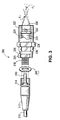
- FIG. 3 which illustrates a representative focusing assembly 300 (which may serve as one of the focusing devices 120 shown in FIG. 1B).
- Laser output is provided by a fiber-optic cable 310 terminating in an SMA (or similar) connector package 312, which includes a threaded collar 314 that is free to rotate.
- the focusing assembly 300 includes a threaded stem 318 that mates with hood 314; a first tubular housing segment 320; and a second housing segment 322.
- Stem 318 is secured to segment 320 by a nut 324.
- the central axis of sleeve 318 passes through segments 320, 322 to define a single continuous bore 330 with an inner wall 331.
- Segments 320 and 322 are locked by a pair of nuts 326, 328.
- Segment 322 contains a pair of focusing lenses 332, 334 at its terminus; alternatively, depending on design, a single focusing lens may suffice.
- segment 320 desirably terminates in a baffle (not shown) that defines an aperture, thereby imposing a fixed radial extent by which emitted radiation can diverge from the central propagated ray. This prevents passage of radiation having NA values above a predetermined limit.
- the baffle may have a sharp, flared edge (such as a conically flared bezel) to avoid reflections.
- hood 314 of SMA connector 312 screwed fully onto stem 318, radiation emitted from the end face of fiber 310 is focused onto a point F 1 . Accordingly, unless a recording construction is disposed precisely at F 1 during imaging, the image spot will not be focused thereon and, as a result, the energy density reaching the recording construction will be less than the available maximum.
- a spacing shim 340 between hood 314 and nut 324, however, the distance between the end face of cable 310 and lenses 332, 334 is increased; as a result, the point of focus moves from F 1 to F 2 .
- r m the demagnification ratio
- hood 314 screwed fully over stem 318 (i.e., without a spacer 340), the analyzer is moved toward and away from lens 334 until the point of maximum energy density is recorded.
- multimode beams can be difficult to characterize with a beam analyzer. In such cases, a different approach to determining the point of focus is necessary.
- a rotatable drum or cylinder 400 bears a recording construction 402 sensitive to the imaging output of a laser (or other optical source).
- the recording construction may be a printing plate, proofing sheet, or any other construction capable of recording in response to imaging radiation. It may be mounted to cylinder 400 or may instead be integral with the cylinder.
- Cylinder 400 is rotated and controller 215 (see FIG. 2) operated to cause each imaging device for which radial alignment is desired -- generally all devices in an array -- to image a patch on construction 402.
- the result is an axial row of patches at the default distance (i.e., the normal working distance between cylinder 400 and the array of imaging devices, and therefore labeled 0).
- the distance between cylinder 400 and the device array is then altered by a fixed increment and the process repeated, with the new row of patches circumferentially displaced from the previously applied row.
- the array-to-cylinder distance is altered through movement of cylinder 400, but the imaging array may be moved instead (or in addition). Additional rows of patches at further array-to-cylinder distance increments are applied to the recording construction 402 until the last device under examination fails perceptibly to affect the recording construction; that is, until the focus has degraded to the point that imaging no longer occurs.
- the recording construction contains a pattern of patches, the rows of which correspond to particular array-to-cylinder distances (each differing by a fixed increment, i.e., 0.5 mil in the illustration), and the circumferential columns of which correspond to the imaging devices L 1 , L 2 , L 3 , etc.
- the patch having a maximum exposure density may be identified as the midpoint of the visible patches -- that is, the patch lying at the midpoint between the non-imaging patches.
- the array-to-cylinder distance increments are chosen to correspond to the thickness of a single shim 340 (taking into account the demagnification ratio), and are desirably sufficiently small that deviation by a single increment will not substantially affect imaging performance.
- the maximum desirable increment depends on the depth-of-focus of the imaging devices. If this parameter is not taken into account and too large an increment is chosen, the optimal array-to-cylinder distance may lie between increments, with the consequence that the devices will not be optimally adjusted for distance and will image at different effective energy densities resulting in visible differences (e.g., if the construction 402 is a printing plate, in the printed copy).
- a fine increment amount allows for arbitrary choice where an even number of patches lie between non-imaging patches.
- the distance to proper focus lies between 0 (the default distance reflecting no adjustment) and -0.5 (i.e., 0.5 mil closer to the imaging device). So long as the increment is sufficiently small, the choice of distance adjustment (i.e., no adjustment vs. an adjustment leading to a -0.5 mil displacement) will not matter. For device L 2 , an adjustment leading to a displacement of -0.5 mil is clearly warranted. And for device L 3 , no adjustment is needed.
Landscapes
- Health & Medical Sciences (AREA)
- General Health & Medical Sciences (AREA)
- Toxicology (AREA)
- Physics & Mathematics (AREA)
- Optics & Photonics (AREA)
- Exposure And Positioning Against Photoresist Photosensitive Materials (AREA)
- Manufacture Or Reproduction Of Printing Formes (AREA)
- Facsimile Scanning Arrangements (AREA)
- Printers Or Recording Devices Using Electromagnetic And Radiation Means (AREA)
Applications Claiming Priority (2)
| Application Number | Priority Date | Filing Date | Title |
|---|---|---|---|
| US09/069,692 US6091434A (en) | 1998-04-29 | 1998-04-29 | Method of calibrating distances between imaging devices and a rotating drum |
| US69692 | 1998-04-29 |
Publications (2)
| Publication Number | Publication Date |
|---|---|
| EP0953453A2 true EP0953453A2 (fr) | 1999-11-03 |
| EP0953453A3 EP0953453A3 (fr) | 2000-09-20 |
Family
ID=22090619
Family Applications (1)
| Application Number | Title | Priority Date | Filing Date |
|---|---|---|---|
| EP99302596A Withdrawn EP0953453A3 (fr) | 1998-04-29 | 1999-04-01 | Méthode de calibration de distances entre dispositifs de formation d'images et un tambour tournant |
Country Status (7)
| Country | Link |
|---|---|
| US (1) | US6091434A (fr) |
| EP (1) | EP0953453A3 (fr) |
| JP (1) | JPH11334024A (fr) |
| KR (1) | KR19990083549A (fr) |
| CN (1) | CN1234529A (fr) |
| AU (1) | AU2602099A (fr) |
| CA (1) | CA2268638A1 (fr) |
Cited By (1)
| Publication number | Priority date | Publication date | Assignee | Title |
|---|---|---|---|---|
| WO2002047915A1 (fr) * | 2000-12-12 | 2002-06-20 | Creo Il. Ltd. | Tete d'imagerie dotee d'un reseau de diodes laser et d'un reseau de tuyau de microlumiere pour la formation de faisceau |
Families Citing this family (1)
| Publication number | Priority date | Publication date | Assignee | Title |
|---|---|---|---|---|
| JP2002154218A (ja) * | 2000-11-21 | 2002-05-28 | Fuji Xerox Co Ltd | インク補給装置及びインクジェット記録装置 |
Citations (2)
| Publication number | Priority date | Publication date | Assignee | Title |
|---|---|---|---|---|
| US5351617A (en) | 1992-07-20 | 1994-10-04 | Presstek, Inc. | Method for laser-discharge imaging a printing plate |
| US5385092A (en) | 1992-07-20 | 1995-01-31 | Presstek, Inc. | Laser-driven method and apparatus for lithographic imaging |
Family Cites Families (4)
| Publication number | Priority date | Publication date | Assignee | Title |
|---|---|---|---|---|
| US4875057A (en) * | 1988-09-01 | 1989-10-17 | Eastman Kodak Company | Modular optical printhead for hard copy printers |
| US5225855A (en) * | 1991-10-24 | 1993-07-06 | Xerox Corporation | Electrographic flare reduction by spacing and gas control |
| DE4203727A1 (de) * | 1992-02-06 | 1993-08-12 | Siemens Ag | Lichtzufuehrvorrichtung |
| US5764274A (en) * | 1996-02-16 | 1998-06-09 | Presstek, Inc. | Apparatus for laser-discharge imaging and focusing elements for use therewith |
-
1998
- 1998-04-29 US US09/069,692 patent/US6091434A/en not_active Expired - Fee Related
-
1999
- 1999-04-01 EP EP99302596A patent/EP0953453A3/fr not_active Withdrawn
- 1999-04-12 CA CA002268638A patent/CA2268638A1/fr not_active Abandoned
- 1999-04-28 AU AU26020/99A patent/AU2602099A/en not_active Abandoned
- 1999-04-28 KR KR1019990015155A patent/KR19990083549A/ko not_active Ceased
- 1999-04-29 CN CN99105359A patent/CN1234529A/zh active Pending
- 1999-04-30 JP JP11123510A patent/JPH11334024A/ja active Pending
Patent Citations (3)
| Publication number | Priority date | Publication date | Assignee | Title |
|---|---|---|---|---|
| US5351617A (en) | 1992-07-20 | 1994-10-04 | Presstek, Inc. | Method for laser-discharge imaging a printing plate |
| US5385092A (en) | 1992-07-20 | 1995-01-31 | Presstek, Inc. | Laser-driven method and apparatus for lithographic imaging |
| US5385092B1 (en) | 1992-07-20 | 1997-10-28 | Presstek Inc | Laser-driven method and apparatus for lithographic imaging |
Cited By (1)
| Publication number | Priority date | Publication date | Assignee | Title |
|---|---|---|---|---|
| WO2002047915A1 (fr) * | 2000-12-12 | 2002-06-20 | Creo Il. Ltd. | Tete d'imagerie dotee d'un reseau de diodes laser et d'un reseau de tuyau de microlumiere pour la formation de faisceau |
Also Published As
| Publication number | Publication date |
|---|---|
| CN1234529A (zh) | 1999-11-10 |
| US6091434A (en) | 2000-07-18 |
| JPH11334024A (ja) | 1999-12-07 |
| EP0953453A3 (fr) | 2000-09-20 |
| KR19990083549A (ko) | 1999-11-25 |
| CA2268638A1 (fr) | 1999-10-29 |
| AU2602099A (en) | 1999-11-11 |
Similar Documents
| Publication | Publication Date | Title |
|---|---|---|
| CA2119965C (fr) | Methode et dispositif de correction et de reglage pour systeme d'imagerie | |
| JP4938783B2 (ja) | 書き込み装置及び書き込み方法 | |
| JPH0862531A (ja) | 複数のレーザ光線を用いた光学システムおよび複数のレーザ光線を用いたプリンタ | |
| JP3254392B2 (ja) | 評価チャート及び画像記録装置 | |
| US6900826B2 (en) | Multiple resolution helical imaging system and method | |
| EP0529532B1 (fr) | Méthode et appareil pour étalonner une imprimante à canaux multiples | |
| JPH09297283A (ja) | レーザ放電像形成装置及びそれに使用する集束要素 | |
| AU746212B2 (en) | Multiple-beam, diode-pumped imaging system | |
| US6091434A (en) | Method of calibrating distances between imaging devices and a rotating drum | |
| EP0549204B1 (fr) | ContrÔle de la position de faisceau dans un appareil à balayage de trame | |
| EP0137559B1 (fr) | Dispositif d'exposition | |
| JP2002189182A (ja) | マルチビーム光源装置 | |
| JPH1138345A (ja) | エラー補正偏向器を有する走査システム | |
| US5745150A (en) | Laser drawing apparatus having drawing beams in a common place aligned with a lens meridian | |
| EP0968834B1 (fr) | Méthode et appareil pour gérer l'operation d'une imprimante | |
| US6166376A (en) | Multi-beam scanning device | |
| US5663554A (en) | Weak lens focus adjusting mechanism based upon thickness of scanned material and imagesetter using same | |
| CA2357684C (fr) | Systeme d'imagerie pompe par diode a plusieurs faisceaux | |
| JP2659028B2 (ja) | 露光装置 | |
| JP2002311368A (ja) | 光走査装置、及び光走査装置のレジ調整・左右倍率調整方法 | |
| JP2004333804A (ja) | 画像露光装置および画像露光方法 | |
| US20020101503A1 (en) | Laser imaging system with variable energy flux densities | |
| JP2003228012A (ja) | 光記録装置 | |
| JPS6145215A (ja) | レ−ザプリンタ | |
| JP2006227508A (ja) | 内面ドラム型画像形成装置 |
Legal Events
| Date | Code | Title | Description |
|---|---|---|---|
| PUAI | Public reference made under article 153(3) epc to a published international application that has entered the european phase |
Free format text: ORIGINAL CODE: 0009012 |
|
| AK | Designated contracting states |
Kind code of ref document: A2 Designated state(s): AT BE CH DE DK ES FR GB GR IE IT LI NL PT SE |
|
| AX | Request for extension of the european patent |
Free format text: AL;LT;LV;MK;RO;SI |
|
| PUAL | Search report despatched |
Free format text: ORIGINAL CODE: 0009013 |
|
| AK | Designated contracting states |
Kind code of ref document: A3 Designated state(s): AT BE CH CY DE DK ES FI FR GB GR IE IT LI LU MC NL PT SE |
|
| AX | Request for extension of the european patent |
Free format text: AL;LT;LV;MK;RO;SI |
|
| RIC1 | Information provided on ipc code assigned before grant |
Free format text: 7B 41J 2/45 A, 7B 41J 2/46 B, 7B 41C 1/10 B, 7G 02B 6/32 B |
|
| 17P | Request for examination filed |
Effective date: 20010307 |
|
| AKX | Designation fees paid |
Free format text: AT BE CH DE DK ES FR GB GR IE IT LI NL PT SE |
|
| STAA | Information on the status of an ep patent application or granted ep patent |
Free format text: STATUS: THE APPLICATION HAS BEEN WITHDRAWN |
|
| 18W | Application withdrawn |
Withdrawal date: 20010802 |