EP0953463B1 - Luftreifen - Google Patents
Luftreifen Download PDFInfo
- Publication number
- EP0953463B1 EP0953463B1 EP99303421A EP99303421A EP0953463B1 EP 0953463 B1 EP0953463 B1 EP 0953463B1 EP 99303421 A EP99303421 A EP 99303421A EP 99303421 A EP99303421 A EP 99303421A EP 0953463 B1 EP0953463 B1 EP 0953463B1
- Authority
- EP
- European Patent Office
- Prior art keywords
- tire
- ply
- turnup
- rubber
- rim
- Prior art date
- Legal status (The legal status is an assumption and is not a legal conclusion. Google has not performed a legal analysis and makes no representation as to the accuracy of the status listed.)
- Expired - Lifetime
Links
- 229920001971 elastomer Polymers 0.000 claims abstract description 65
- 239000003351 stiffener Substances 0.000 claims abstract description 25
- 229910000831 Steel Inorganic materials 0.000 claims description 39
- 239000010959 steel Substances 0.000 claims description 39
- 239000011324 bead Substances 0.000 claims description 25
- 230000003014 reinforcing effect Effects 0.000 claims description 18
- 230000002093 peripheral effect Effects 0.000 claims description 4
- 230000000052 comparative effect Effects 0.000 description 14
- 238000005452 bending Methods 0.000 description 6
- 239000002131 composite material Substances 0.000 description 5
- 230000006835 compression Effects 0.000 description 5
- 238000007906 compression Methods 0.000 description 5
- 238000012360 testing method Methods 0.000 description 5
- 229920000297 Rayon Polymers 0.000 description 4
- 230000003247 decreasing effect Effects 0.000 description 4
- 239000002964 rayon Substances 0.000 description 4
- 238000005260 corrosion Methods 0.000 description 3
- 230000007797 corrosion Effects 0.000 description 3
- 238000004519 manufacturing process Methods 0.000 description 3
- 238000000034 method Methods 0.000 description 3
- 238000000926 separation method Methods 0.000 description 3
- XLYOFNOQVPJJNP-UHFFFAOYSA-N water Substances O XLYOFNOQVPJJNP-UHFFFAOYSA-N 0.000 description 3
- 229920000271 Kevlar® Polymers 0.000 description 2
- 239000000835 fiber Substances 0.000 description 2
- 238000011835 investigation Methods 0.000 description 2
- 239000004761 kevlar Substances 0.000 description 2
- 239000004677 Nylon Substances 0.000 description 1
- 229920002302 Nylon 6,6 Polymers 0.000 description 1
- 238000005299 abrasion Methods 0.000 description 1
- 230000015556 catabolic process Effects 0.000 description 1
- 238000006731 degradation reaction Methods 0.000 description 1
- 238000006073 displacement reaction Methods 0.000 description 1
- 230000000694 effects Effects 0.000 description 1
- 238000011156 evaluation Methods 0.000 description 1
- 230000002349 favourable effect Effects 0.000 description 1
- 229920005555 halobutyl Polymers 0.000 description 1
- 230000008676 import Effects 0.000 description 1
- 238000010348 incorporation Methods 0.000 description 1
- 239000011159 matrix material Substances 0.000 description 1
- 238000005259 measurement Methods 0.000 description 1
- 229920001778 nylon Polymers 0.000 description 1
- 230000008520 organization Effects 0.000 description 1
- 230000035515 penetration Effects 0.000 description 1
- 229920000728 polyester Polymers 0.000 description 1
- 230000000630 rising effect Effects 0.000 description 1
- 229920006395 saturated elastomer Polymers 0.000 description 1
- 238000004804 winding Methods 0.000 description 1
Images





Classifications
-
- B—PERFORMING OPERATIONS; TRANSPORTING
- B60—VEHICLES IN GENERAL
- B60C—VEHICLE TYRES; TYRE INFLATION; TYRE CHANGING; CONNECTING VALVES TO INFLATABLE ELASTIC BODIES IN GENERAL; DEVICES OR ARRANGEMENTS RELATED TO TYRES
- B60C15/00—Tyre beads, e.g. ply turn-up or overlap
- B60C15/0009—Tyre beads, e.g. ply turn-up or overlap features of the carcass terminal portion
- B60C15/0072—Tyre beads, e.g. ply turn-up or overlap features of the carcass terminal portion with ply reverse folding, i.e. carcass layer folded around the bead core from the outside to the inside
-
- B—PERFORMING OPERATIONS; TRANSPORTING
- B60—VEHICLES IN GENERAL
- B60C—VEHICLE TYRES; TYRE INFLATION; TYRE CHANGING; CONNECTING VALVES TO INFLATABLE ELASTIC BODIES IN GENERAL; DEVICES OR ARRANGEMENTS RELATED TO TYRES
- B60C15/00—Tyre beads, e.g. ply turn-up or overlap
- B60C15/0009—Tyre beads, e.g. ply turn-up or overlap features of the carcass terminal portion
- B60C15/0018—Tyre beads, e.g. ply turn-up or overlap features of the carcass terminal portion not folded around the bead core, e.g. floating or down ply
-
- B—PERFORMING OPERATIONS; TRANSPORTING
- B60—VEHICLES IN GENERAL
- B60C—VEHICLE TYRES; TYRE INFLATION; TYRE CHANGING; CONNECTING VALVES TO INFLATABLE ELASTIC BODIES IN GENERAL; DEVICES OR ARRANGEMENTS RELATED TO TYRES
- B60C15/00—Tyre beads, e.g. ply turn-up or overlap
- B60C15/06—Flipper strips, fillers, or chafing strips and reinforcing layers for the construction of the bead
-
- B—PERFORMING OPERATIONS; TRANSPORTING
- B60—VEHICLES IN GENERAL
- B60C—VEHICLE TYRES; TYRE INFLATION; TYRE CHANGING; CONNECTING VALVES TO INFLATABLE ELASTIC BODIES IN GENERAL; DEVICES OR ARRANGEMENTS RELATED TO TYRES
- B60C17/00—Tyres characterised by means enabling restricted operation in damaged or deflated condition; Accessories therefor
- B60C17/0009—Tyres characterised by means enabling restricted operation in damaged or deflated condition; Accessories therefor comprising sidewall rubber inserts, e.g. crescent shaped inserts
-
- B—PERFORMING OPERATIONS; TRANSPORTING
- B60—VEHICLES IN GENERAL
- B60C—VEHICLE TYRES; TYRE INFLATION; TYRE CHANGING; CONNECTING VALVES TO INFLATABLE ELASTIC BODIES IN GENERAL; DEVICES OR ARRANGEMENTS RELATED TO TYRES
- B60C9/00—Reinforcements or ply arrangement of pneumatic tyres
- B60C9/02—Carcasses
- B60C9/04—Carcasses the reinforcing cords of each carcass ply arranged in a substantially parallel relationship
- B60C9/08—Carcasses the reinforcing cords of each carcass ply arranged in a substantially parallel relationship the cords extend transversely from bead to bead, i.e. radial ply
-
- Y—GENERAL TAGGING OF NEW TECHNOLOGICAL DEVELOPMENTS; GENERAL TAGGING OF CROSS-SECTIONAL TECHNOLOGIES SPANNING OVER SEVERAL SECTIONS OF THE IPC; TECHNICAL SUBJECTS COVERED BY FORMER USPC CROSS-REFERENCE ART COLLECTIONS [XRACs] AND DIGESTS
- Y10—TECHNICAL SUBJECTS COVERED BY FORMER USPC
- Y10T—TECHNICAL SUBJECTS COVERED BY FORMER US CLASSIFICATION
- Y10T152/00—Resilient tires and wheels
- Y10T152/10—Tires, resilient
- Y10T152/10495—Pneumatic tire or inner tube
- Y10T152/10819—Characterized by the structure of the bead portion of the tire
-
- Y—GENERAL TAGGING OF NEW TECHNOLOGICAL DEVELOPMENTS; GENERAL TAGGING OF CROSS-SECTIONAL TECHNOLOGIES SPANNING OVER SEVERAL SECTIONS OF THE IPC; TECHNICAL SUBJECTS COVERED BY FORMER USPC CROSS-REFERENCE ART COLLECTIONS [XRACs] AND DIGESTS
- Y10—TECHNICAL SUBJECTS COVERED BY FORMER USPC
- Y10T—TECHNICAL SUBJECTS COVERED BY FORMER US CLASSIFICATION
- Y10T152/00—Resilient tires and wheels
- Y10T152/10—Tires, resilient
- Y10T152/10495—Pneumatic tire or inner tube
- Y10T152/10819—Characterized by the structure of the bead portion of the tire
- Y10T152/10837—Bead characterized by the radial extent of apex, flipper or chafer into tire sidewall
-
- Y—GENERAL TAGGING OF NEW TECHNOLOGICAL DEVELOPMENTS; GENERAL TAGGING OF CROSS-SECTIONAL TECHNOLOGIES SPANNING OVER SEVERAL SECTIONS OF THE IPC; TECHNICAL SUBJECTS COVERED BY FORMER USPC CROSS-REFERENCE ART COLLECTIONS [XRACs] AND DIGESTS
- Y10—TECHNICAL SUBJECTS COVERED BY FORMER USPC
- Y10T—TECHNICAL SUBJECTS COVERED BY FORMER US CLASSIFICATION
- Y10T152/00—Resilient tires and wheels
- Y10T152/10—Tires, resilient
- Y10T152/10495—Pneumatic tire or inner tube
- Y10T152/10855—Characterized by the carcass, carcass material, or physical arrangement of the carcass materials
- Y10T152/10864—Sidewall stiffening or reinforcing means other than main carcass plies or foldups thereof about beads
Definitions
- This invention relates to a pneumatic tire, and more particularly to a pneumatic radial tire of so-called run-flat type capable of running over a given distance at a state that an inner pressure is zero or neat to zero due to puncture or the like.
- the invention relates to a pneumatic radial tire having a relatively large ratio of section height to section width or an aspect ratio of not less than 60 and an excellent run-flat durability (running at puncture state).
- US-A-4 261 405 shows a tire of this type disclosing the features of the preamble of claim 1.
- run-flat tire The run-flat type radial tire (hereinafter referred to as run-flat tire) is mainly applied to vehicles such as passenger cars and the like wherein a bearing load of the tire is relatively small, and is required to satisfy a condition that even if the tire is suddenly rendered into a flat state (or puncture state) during the running on general-purpose road or high-speed running on an expressway, it can stably be run without damaging the handling stability of the vehicle or the passenger car and particularly the tire can stably and surely be run up to a tire exchangeable place over a given distance of, for example, 80-160 km without separating off from a used rim (or recommended rim) and causing breakage even in the continuation of the running.
- run-flat tires having various structures are proposed or sometimes in a combination of a fully worked-out rim to be used.
- the tires relating to these proposals are roughly divided into super-low section profile tires having an aspect ratio of less than 60 and tires having an aspect ratio of not less than 60 and being relatively high in the section height.
- a run-flat tire being excellent in the cost performance and most practically used in markets is a tire having a structure that as a section of a tire 21 is shown in Fig. 5, a pair of thick reinforcing rubber strips 29 each having a crescent-shaped section are applied to an inner face side of an innermost carcass ply 26-1 extending from a bead portion 22 through a sidewall portion 23 to an end part of a tread portion 24.
- this type of the tire can not avoid the rise of the cost, so that it is frequently mounted onto an expensive vehicle assuming high-speed running such as a sport car, a sport-type car and the like.
- a radial carcass 26 has a two or more ply structure comprising a turnup ply 26-1 wound around a bead core 25 from inside of the tire toward outside and a down ply 26-2 enveloping the turnup ply 26-1 from the outside in order to mitigate a deformation degree crushed under flat running as far as possible.
- a hard stiffener rubber 27 extending from an outer peripheral surface of the bead core 25 up to a position near to a maximum tire width S is arranged so as to sandwich between the turnup ply 26-1 and the down ply 26-2.
- a rubberized layer containing Kevlar cords or steel cords therein (called as an insert ply) is sometimes arranged so as to extend from the bead portion 22 to the sidewall portion 23.
- the tires having a relatively high section height as mentioned above are frequently mounted onto high-grade import passenger cars and high-grade domestic passenger cars having a relatively large displacement. In this case, it is possible to run the tire in cooperation with an installed rim at a run-flat state.
- a type of incorporating a tire support member into the rim is main current.
- an object of the invention to provide a pneumatic tire having particularly an aspect ratio of not less than 60 in which the safe running of the vehicle such as passenger car or the like is guaranteed even if rapid air leakage is caused due to puncture or the like while maintaining the good rim assembling property and the ride comfort against vibrations within an acceptable range without bringing about inconvenience in the production and remarkable cost rise and the performance of preventing the separation of the tire from the rim in the run-flat running and the durability are improved to a level satisfied by a user as a run-flat tire.
- a pneumatic tire comprising a radial carcass of at least one rubberized cord ply extending between a pair of bead cores embedded in a pair of bead portion and reinforcing a pair of sidewall portions and a tread portion, a stiffener rubber taperingly extending from an outer peripheral surface of the bead core toward the tread portion, said carcass comprising a turnup ply wound around the bead core from inside of the tire toward outside thereof so as to envelop the stiffener rubber, and a pair of reinforcing rubber strips each having a crescent-shaped section and extending along an inner face side of an innermost tumup ply from a position near to the bead core in the bead portion through the sidewall portion to an end part of the tread portion, the improvement wherein at a section of a tire-rim assembly when the tire is assembled onto a recommended rim and inflated under an internal pressure corresponding to 15% of a maximum air pressure for
- maximum air pressure and "recommended rim” used herein are according to Standards Manual 1998 of The European Tire and Rim Technical Organization (hereinafter referred to as ETRTO standard). More detailedly, there are used numerical values and rim size described on “Table of air pressure load capacity” and “Table of recommended rim” defined every kind of tires according to ETRTO standard.
- the wording "assembling of tire onto recommended rim” means an assembled state that the tire assembled onto the recommended rim is inflated under an air pressure above the maximum air pressure to sufficiently assemble the tire onto the recommended rim and then the filled air or gas is discharged to an internal pressure of zero while holding the sufficiently assembled state.
- the discharge of the filled air may be adjusted to a pressure corresponding to 15% of the maximum air pressure before the arrival to an internal pressure of zero.
- rim diameter line means a straight line parallel to a rotating axis of the tire in an actual value of a rim diameter ( ⁇ D) on each recommended rim described in a chapter "Rim Profile" of the ETRTO standard.
- a cord at least used for the turnup ply of the carcass is a steel cord, and a turnup portion of the turnup ply is contacted with a main body of the turnup ply inward from the line segment PA in the radial direction of the tire, and the turnup portion of the turnup ply extends over the top of the stiffener rubber and is contacted with the main body of the turnup ply at a position exceeding the top of the stiffener rubber.
- the term "main body of the turnup ply" used herein means a portion of the turnup ply other than the turnup portion and extending between the bead cores.
- the steel cord for the turnup ply has a cord twisting structure of 1 ⁇ n (n is an integer of 2-7), and a filament diameter of the steel cord is within a range of 0.125-0.275 mm, and a ratio of rubber gauge Gf between an outer surface of the tire and an outer surface of an outermost ply on the line segment PA to maximum gauge Gh of the reinforcing rubber strip (Gf/Gh) is within a range of 0.8-1.4.
- FIG. 1 is shown an tire-rim assembly formed by assembling the pneumatic tire according to the invention into a recommended rim
- Fig. 2 is an enlarged section view of a main part shown in Fig. 1
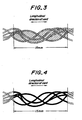
- Fig. 3 is a diagrammatically X-ray photograph of a rubberized steel cord used for a carcass ply in the tire
- Fig. 4 is a diagrammatically X-ray photograph of only a steel cord excluding rubber shown in Fig. 3.
- numeral 1 is a pneumatic tire for passenger car.
- the tire 1 comprises a pair of bead portions 2, a pair of sidewall portions 3, a tread portion 4 connecting to both the sidewall portions 3, and a radial carcass 6 of one or more rubberized cord plies, two plies in the illustrated embodiment extending between a pair of bead cores 5 embedded in the bead portions 2 and reinforcing the portions 2, 3, 4.
- the carcass 6 of the illustrated embodiment comprises a turnup ply 6-1 wound around the bead core 5 from inside of the tire toward outside thereof to form a turnup portion 6-1u having a turnup end 6-1uE, and a down ply 6-2 enveloping a main body of the turnup ply 6-1 and the turnup portion 6-1u from outside and terminated in the vicinity of the bead core 5.
- the turnup ply 6-1 forms an innermost carcass ply.
- the carcass 6 may comprise only the turnup ply 6-1 without using the down ply 6-2.
- the tire 1 has a stiffener rubber 7 taperingly extending from an outer peripheral surface of the bead core 5 toward the tread portion 4.
- the turnup ply 6-1 envelops the stiffener rubber 7 with its main body and turnup portion 6-1u.
- cord at least used for the turnup ply 6-1 is a steel cord.
- the cord for the turnup ply 6-1 may be an organic fiber cord such as rayon cord, nylon cord or the like.
- the invention is described with respect to the use of the steel cord in all plies of the carcass 6.
- the belt 8 comprises two or more layers, two cross cord layers in the illustrated embodiment, desirably two cross steel cord layers and further has an organic fiber cord layer shown by dotted lines in Fig. 1 enveloping the two cross steel cord layers, for example, a helically winding layer of nylon-66 cord or Kevlar cord.
- the cross steel cord layers are arranged so as to cross the steel cords of these layers with each other with respect to an equatorial plane E of the tire.
- a width of the steel cord layer adjacent to the carcass 6 is wider than that of an outer steel cord layer.
- the tire 1 is provided a pair of reinforcing rubber strips 9, which is inherent to a run-flat tire, each having a crescent-shaped section and located at an inner face side of the turnup ply 6-1 in the carcass 6.
- Numeral 10 is an innerliner of halogenated butyl rubber having an air impermeability. Therefore, the tire 1 is a tubeless tire.
- Fig. 1 is sectionally shown a tire-rim assembly formed by assembling the tire 1 onto a recommended rim 15 (according to the above ETRTO standard, shown by only a profile line) and inflated under a slight air pressure corresponding to 15% of a maximum air pressure of the tire 1 (according to the above ETRTO standard).
- the section of the assembly inflated under such a slight air pressure as a whole must satisfy the following condition.
- the turnup portion 6-1u of the turnup ply 6-1 is contacted with the main body of the turnup ply 6-1 inward from the standard line PA in the radial direction of the tire 1.
- the turnup portion 6-1u of the turnup ply 6-1 extends over the top C of the stiffener rubber 7 outward in the radial direction of the tire 1 and a part of the turnup portion 6-1u exceeding the top C of the stiffener rubber 7 is arranged so as to contact with the main body of the turnup ply 6-1.
- the section height SH of the tire under a maximum air pressure is deformed by a large deflection ⁇ at the flat state.
- the deflection ⁇ becomes larger, the run-flat durability lowers, while as the deflection ⁇ becomes small, the run-flat durability improves. That is, the deflection ⁇ is inversely proportional to the run-flat durability as mentioned below.
- each of these tires has the conventional structure shown in Fig. 5 and a tire size of 215/65R15.
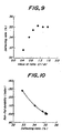
- the deflecting ratio is 37.8% in the conventional tire 21B and 38.5% in the comparative tire 21C, while that is held to 35.0% in the tire 21A (using the steel cords).
- the run-flat durability is evaluated by pushing each of the tires onto a drum rotating at a surface speed of 89 km/h at an internal pressure of zero (state removing a valve core) under a load of 540 kgf corresponding to about 76% of a maximum load capacity (710 kgf) of the tire and measuring a running distance until the occurrence of trouble.
- the evaluation results are represented by an index on the basis that the conventional tire 21B is 100, in which the larger the index value, the better the durability.
- the index value of the run-flat durability is 95 in the comparative tire 21C, while that is 138 in the tire 21A using the steel cord ply in the carcass 26.
- the tire 21A using the steel cords in the plies 26-1, 26-2 of the carcass 26 can make the deflecting ratio (%) smaller that those of the other tires 21B, 21C and largely improves the run-flat durability. And also, it is apparent that the deflecting ratio (%) and the run-flat durability have substantially a relation of inverse proportion.
- a tensile strain region is existent in ⁇ zone shown by a surrounding of a solid line inward from the line segment PA in the radial direction of the tire and at the inside of the tire in the bead portion 22 and its neighborhood and hence a compression region is existent outward from the ⁇ zone and from dotted lines. Furthermore, a tensile strain region is existent in ⁇ zone shown by a surrounding of a solid line at the outside of the tire in the sidewall portion 23 and hence a compression region is existent inward from the ⁇ zone and from dotted lines.
- the ⁇ zone is a zone ranging from a position that an innermost height h from the rim diameter line RL in the radial direction of the tire is 0.35 times a height SHp of the innermost ply 26-1 from the rim diameter line RL to a position that an outermost height H from the rim diameter line RL in the radial direction of the tire is 0.90 times the height SHp.
- the steel cords are used as the cord of the carcass ply existing in these ⁇ , ⁇ zones, a large tensile rigidity inherent to the steel cord can advantageously be utilized to reduce the deflection ⁇ and hence it is possible to decrease the deflecting ratio (%).
- the range of the tensilezone ⁇ is wide and the value of the tensile strain is large, so that the top C of the stiffener rubber 7 is located inward from the standard line (line segment) PA (see Figs.
- a ratio (Cr/Ar) of height Cr of the top C of the stiffener rubber measured from the rim diameter line RL to height Ar of the intersect A of the standard line (line segment) PA measured from the rim diameter line RL is 0.45 in Example 1, 0.71 in Example 2 and 0.88 in Example 3.
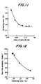
- the deflecting ratio of the tire is 32.8% in Example 1, 34.0% in Example 2, 34.7% in Example 3, 35.1% in Comparative Example 1, 35.0% in Comparative Example 2, and 35.0% in Comparative Example 3.
- the deflecting ratio of the tire 21A is 35.0%.
- the running distance until the occurrence of trouble is represented by an index on the basis that the tire 21A is 100.
- the index value of the running distance is 128 in Example 1, 110 in Example 2, 103 in Example 3, 100 in Comparative Example 1, 101 in Comparative Example 2 and 101 in Comparative Example 3.
- the ratio Cr/Ar is adaptable to be less than 1.0, desirably 0.45-0.88.
- the run-flat durability of the tire 1 is largely improved by applying the steel cord to at least turnup ply 6-1 among the plies of the carcass 6, locating the top C of the stiffener rubber 7 inward from the standard line PA in the radial direction of the tire, and contacting the turnup portion 6-1u of the turnup ply 6-1 with the main body of the turnup ply 6-1 inward from the standard line PA in the radial direction of the tire.
- Example 1 is 100 in Tale 1. Items Examples 1 4 5 6 7 8 Maximum rubber gauge Gh (mm) 11.2 11.2 11.2 11.2 11.2 11.2 11.2 Rubber gauge Gf (mm) 8.1 6.0 10.0 11.8 13.7 15.2 Ratio Gf/Gh 0.72 0.54 0.90 1.05 1.22 1.36 Deflecting ratio (%) 32.8 34.5 32.0 31.8 31.7 31.7 Tire weight (kgf) 19.44 18.50 20.28 21.08 21.87 22.40 Run-flat durability (index) 100 84 117 121 120 121 Durability index/weight (index) 100 88 112 111 106 105 Trouble position rubber 7 rubber 7 rubber 7 rubber 9 rubber 9 rubber 9 rubber 9 rubber 9 rubber 9
- the cord twisting structure of the steel cord used in the carcass 6, 26 of the aforementioned tire is 1 ⁇ 5 ⁇ 0.15.
- the steel cord having a cord twisting structure of 1 x n (n is an integer of 2-7) and a filament diameter of 0.125-0.275 mm is suitable for the plies 6-1, 6-2 in the carcass 6 of the tire 1.
- the steel cord used in the invention is favorable to have a high elongation property that total elongation at break of a cord at a bare state (according to JIS G3510-1986) is not less than 3.5%, desirably not less than 4.0%.
- the steel cord must satisfy a property based on the following test.
- a ratio of total area of steel filaments occupied in an area of a cord composite excluding a portion projected from an outermost filament (area occupying ratio R) in a length of 15 mm in a longitudinal direction optionally selected from the X-ray photograph of one steel cord-rubber composite, which is taken out from the plies 6-1, 6-2 of the carcass 6, is within a range of 0.45-0.95.
- the length of 15 mm in the longitudinal direction of the cord means 15 mm as a cord length in the X-ray photograph.
- the area occupying ratio R is an average of 10 measured values when an X-ray is irradiated to the sidewall portion 3 in the vicinity of a position S of a maximum width of the tire 1 from a direction perpendicular to the surface of the sidewall portion 3 at 10 places in the circumferential direction of the tire by using K-2 model made by Softec Co., Ltd. to obtain 10 X-ray photographs.
- the area occupying ratio R is less than 0.45, a contact area between each filament and rubber increases to more control corrosion propagation through water content, but a tensile modulus as the steel cord becomes too low and hence the bending rigidity required in the carcass 6 can not be satisfied, while when the area occupying ratio R exceeds 0.95, the filament itself hardly deforms and the resistance to compression fatigue is degraded.
- the area occupying ratio R is preferably within a range of 0.50-0.90, more particularly 0.55-0.75.
- the steel cord used in the plies 6-1, 6-2 of the carcass 6 is so-called open twisted cord having a wide space in an inside of an outer cord envelop in which the filaments are substantially independent in rubber matrix and contact with each other in a point.
- the contact area between each filament of the cord and rubber can be increased to a maximum to control the abrasion due to the friction between the mutual filaments or fretting, and also the penetration of water into a space between mutual filaments of the cord can be prevented and hence the corrosion propagation through water mainly resulted in the degradation of the durability in the steel cord can be controlled to largely improve the corrosion resistance.
- a greater amount of rubber existing in the inside of the steel cord contributes to increase the bending rigidity of the steel cord.
- pneumatic tires having particularly an aspect ratio of not less than 60 which hold a good rim-assembling property without using the tire support member and maintain the ride comfort against vibrations at an acceptable range without considerably raising the cost and damaging the productivity in the building operation in view of the production, and guarantee the safe running of the vehicle such as passenger car or the like even in the rapid air leakage due to puncture or the like and can improve the performance of preventing the separation of the tire from the rim and the durability in the run-flat running to levels satisfied by a user as a run-flat tire.
Landscapes
- Engineering & Computer Science (AREA)
- Mechanical Engineering (AREA)
- Tires In General (AREA)
Claims (6)
- Luftreifen (1), aufweisend eine radiale Karkasse (6) aus mindestens einer gummigetrankten Cordlage, die sich zwischen zwei in zwei Wulstbereiche (2) eingebetteten Wulstkernen (5) erstreckt und zwei Seitenwandbereiche (3) und einen Laufflächenbereich (4) verstärkt, einen Versteifungsgummi (7), der sich von der äußeren Umfangsoberfläche des Wulstkerns (5) zu dem Laufflächenbereich (4) hin konisch erstreckt, wobei die Karkasse (6) eine Umstülplage (6-1) aufweist, die von der Innenseite nach der Außenseite des Reifens so um den Wulstkern (5) geschlungen ist, daß sie den Versteifvngsgummi (7) umhüllt, und zwei Verstärkungsgummistreifen (9), von denen jeder einen halbmondförmigen Querschnitt hat und sich von einer nahe bei dem Wulstkern (5) gelegenen Position in dem Wulstbereich (2) über den Seitenwandbereich (3) bis zu einem Endteil des Laufflächenbereichs (4) längs einer inneren Fläche der innersten Umstülplage erstreckt, dadurch gekennzeichnet, daß in einem Schnitt einer Reifen-Felgen-Einheit, wenn der Reifen (1) auf einer empfohlenen Felge (15) angebracht ist und auf einen inneren Druck aufgeblasen ist, der 15% des maximalen Luftdrucks des Reifens entspricht, das obere Ende (C) des Versteifungsgummis (7) in der radialen Richtung des Reifens innerhalb von einem Linienabschnitt (PA) gelegen ist, der den Mittelpunkt (P) eines Bogens bei einem Flanschprofil der Felge (15) mit einem Schnittpunkt (A) zwischen einer geraden Linie (Q) und der inneren Fläche des Reifens verbindet, wobei die gerade Linie (Q) von dem Mittelpunkt (P) unter einem Winkel von 60° bezüglich einer geraden Linie (L), die parallel zu einer Felgendurchmesserlinie (RL) ist, zu dem Reifen hin gezogen ist.
- Luftreifen wie in Anspruch 1 beansprucht, dadurch gekennzeichnet, daß der für die Umstülplage (6-1) der Karkasse (6) verwendete Cord Stahlcord ist.
- Luftreifen wie in Anspruch 1 oder 2 beansprucht, dadurch gekennzeichnet, daß der Umstülpbereich (6-1u) der Umstülplage (6-1) den Hauptkörper der Umstülplage in der radialen Richtung des Reifens innerhalb des Linienabschnitts (PA) berührt.
- Luftreifen wie in Anspruch 3 beansprucht, dadurch gekennzeichnet, daß sich der Umstülpbereich (6-1u) der Umstülplage (6-1) bis über das obere Ende (C) des Versteifungsgummis (7) erstreckt und bei einer Position über dem oberen Ende des Versteifungsgummis den Hauptkörper der Umstülplage berührt.
- Luftreifen wie in Anspruch 2 beansprucht, dadurch gekennzeichnet, daß der Stahlcord für die Umstülplage (6-1) die Gordfaden-Verdrillstruktur 1 x n (n ist eine ganze Zahl von 2-7) hat, und der Filamentdurchmesser des Stahlcords in dem Bereich von 0,125-0,275 mm liegt.
- Luftreifen wie in irgendeinem der Ansprüche 1 bis 5 beansprucht, dadurch gekennzeichnet, daß das Verhältnis der Crummidicke (Gf) zwischen der äußeren Oberfläche des Reifens und der äußeren Oberfläche der äußersten Lage auf dem Linienabschnitt (PA) zu der maximalen Dicke (Gh) des Verstärkungsgummistreifens, (Gf/Gh), in dem Bereich von 0,8-1,4 liegt.
Applications Claiming Priority (2)
| Application Number | Priority Date | Filing Date | Title |
|---|---|---|---|
| JP12142198 | 1998-04-30 | ||
| JP10121421A JPH11310017A (ja) | 1998-04-30 | 1998-04-30 | 空気入りタイヤ |
Publications (3)
| Publication Number | Publication Date |
|---|---|
| EP0953463A2 EP0953463A2 (de) | 1999-11-03 |
| EP0953463A3 EP0953463A3 (de) | 2001-03-14 |
| EP0953463B1 true EP0953463B1 (de) | 2003-12-03 |
Family
ID=14810737
Family Applications (1)
| Application Number | Title | Priority Date | Filing Date |
|---|---|---|---|
| EP99303421A Expired - Lifetime EP0953463B1 (de) | 1998-04-30 | 1999-04-30 | Luftreifen |
Country Status (5)
| Country | Link |
|---|---|
| US (1) | US6119748A (de) |
| EP (1) | EP0953463B1 (de) |
| JP (1) | JPH11310017A (de) |
| DE (1) | DE69913239T2 (de) |
| ES (1) | ES2210980T3 (de) |
Families Citing this family (12)
| Publication number | Priority date | Publication date | Assignee | Title |
|---|---|---|---|---|
| JP4390932B2 (ja) * | 1998-11-19 | 2009-12-24 | 株式会社ブリヂストン | 空気入りタイヤ |
| JP2001071715A (ja) * | 1999-09-09 | 2001-03-21 | Bridgestone Corp | 空気入りタイヤ |
| WO2005082646A1 (en) * | 2004-03-01 | 2005-09-09 | Bridgestone Corporation | Process for repairing punctured pneumatic tire in tire-rim assembly and repairing system |
| JP2006131001A (ja) * | 2004-11-04 | 2006-05-25 | Bridgestone Corp | 空気入りタイヤ及び空気入りタイヤ製造方法 |
| JP4667170B2 (ja) * | 2005-08-30 | 2011-04-06 | 株式会社ブリヂストン | 安全タイヤ及び安全タイヤとリムの組立体 |
| JP5046556B2 (ja) * | 2006-05-19 | 2012-10-10 | 株式会社ブリヂストン | 安全タイヤ |
| JP5046555B2 (ja) * | 2006-05-19 | 2012-10-10 | 株式会社ブリヂストン | 安全タイヤ |
| JP5039326B2 (ja) * | 2006-06-12 | 2012-10-03 | 株式会社ブリヂストン | 安全タイヤ |
| JP5519341B2 (ja) * | 2010-03-10 | 2014-06-11 | 株式会社ブリヂストン | ランフラットタイヤ |
| JP6055587B2 (ja) * | 2011-03-17 | 2016-12-27 | 株式会社ブリヂストン | 空気入りタイヤ |
| JP6965597B2 (ja) * | 2017-06-26 | 2021-11-10 | 住友ゴム工業株式会社 | ランフラットタイヤ及びその製造方法 |
| WO2020090750A1 (ja) * | 2018-10-31 | 2020-05-07 | 株式会社ブリヂストン | タイヤ |
Family Cites Families (5)
| Publication number | Priority date | Publication date | Assignee | Title |
|---|---|---|---|---|
| US4193437A (en) * | 1977-09-16 | 1980-03-18 | The B. F. Goodrich Company | Self supporting tire |
| JPS5559005A (en) * | 1978-10-30 | 1980-05-02 | Bridgestone Corp | Air-filled safety tire |
| JP2913322B2 (ja) * | 1989-09-08 | 1999-06-28 | 横浜ゴム株式会社 | ランフラット空気入りラジアルタイヤ |
| JPH0456608A (ja) * | 1990-06-25 | 1992-02-24 | Yokohama Rubber Co Ltd:The | 乗用車用空気入りタイヤ |
| AU728296B2 (en) * | 1997-05-29 | 2001-01-04 | Goodyear Tire And Rubber Company, The | Tire with composite ply structure and method of manufacture |
-
1998
- 1998-04-30 JP JP10121421A patent/JPH11310017A/ja not_active Withdrawn
-
1999
- 1999-04-30 ES ES99303421T patent/ES2210980T3/es not_active Expired - Lifetime
- 1999-04-30 DE DE69913239T patent/DE69913239T2/de not_active Expired - Fee Related
- 1999-04-30 EP EP99303421A patent/EP0953463B1/de not_active Expired - Lifetime
- 1999-04-30 US US09/302,984 patent/US6119748A/en not_active Expired - Lifetime
Also Published As
| Publication number | Publication date |
|---|---|
| DE69913239T2 (de) | 2004-09-30 |
| DE69913239D1 (de) | 2004-01-15 |
| JPH11310017A (ja) | 1999-11-09 |
| US6119748A (en) | 2000-09-19 |
| EP0953463A2 (de) | 1999-11-03 |
| EP0953463A3 (de) | 2001-03-14 |
| ES2210980T3 (es) | 2004-07-01 |
Similar Documents
| Publication | Publication Date | Title |
|---|---|---|
| EP0984867B1 (de) | Ein unausdehnbarer hochtemperaturfester notlaufreifen | |
| EP0826524B1 (de) | Radiale Luftreifen | |
| EP0988159B1 (de) | Kostengünstiger, leichter, radialer reifen | |
| EP0994783B1 (de) | Leichter radialer reifen mit glasfaserngürtel | |
| EP1002668B1 (de) | Luftreifen | |
| EP1019257B1 (de) | Leichter radialer reifen mit aramid-gürtel | |
| US6527025B1 (en) | Tubeless tire | |
| EP1095797B1 (de) | Luftreifen | |
| EP0953463B1 (de) | Luftreifen | |
| US5188685A (en) | Pneumatic radial tire including steel belt cords of 2+2x.30ht construction | |
| EP1366930B1 (de) | Radiale LKW-Reifen | |
| EP1176033A2 (de) | Radiale Luftreifen | |
| JPH11227427A (ja) | 空気入り安全タイヤ | |
| EP4257371B1 (de) | Luftreifen | |
| US6138732A (en) | Pneumatic tires with run flat reinforcing strip rubber | |
| EP1676731B1 (de) | Radial reifen | |
| JPH11321251A (ja) | 空気入りタイヤ | |
| US12508849B2 (en) | Tire | |
| US20240262130A1 (en) | Tire | |
| AU724426C (en) | Light weight fiberglass belted radial tire |
Legal Events
| Date | Code | Title | Description |
|---|---|---|---|
| PUAI | Public reference made under article 153(3) epc to a published international application that has entered the european phase |
Free format text: ORIGINAL CODE: 0009012 |
|
| AK | Designated contracting states |
Kind code of ref document: A2 Designated state(s): DE ES FR GB IT |
|
| AX | Request for extension of the european patent |
Free format text: AL;LT;LV;MK;RO;SI |
|
| PUAL | Search report despatched |
Free format text: ORIGINAL CODE: 0009013 |
|
| AK | Designated contracting states |
Kind code of ref document: A3 Designated state(s): AT BE CH CY DE DK ES FI FR GB GR IE IT LI LU MC NL PT SE |
|
| AX | Request for extension of the european patent |
Free format text: AL;LT;LV;MK;RO;SI |
|
| 17P | Request for examination filed |
Effective date: 20010301 |
|
| AKX | Designation fees paid |
Free format text: DE ES FR GB IT |
|
| GRAH | Despatch of communication of intention to grant a patent |
Free format text: ORIGINAL CODE: EPIDOS IGRA |
|
| GRAS | Grant fee paid |
Free format text: ORIGINAL CODE: EPIDOSNIGR3 |
|
| GRAA | (expected) grant |
Free format text: ORIGINAL CODE: 0009210 |
|
| AK | Designated contracting states |
Kind code of ref document: B1 Designated state(s): DE ES FR GB IT |
|
| REG | Reference to a national code |
Ref country code: GB Ref legal event code: FG4D |
|
| REF | Corresponds to: |
Ref document number: 69913239 Country of ref document: DE Date of ref document: 20040115 Kind code of ref document: P |
|
| REG | Reference to a national code |
Ref country code: ES Ref legal event code: FG2A Ref document number: 2210980 Country of ref document: ES Kind code of ref document: T3 |
|
| ET | Fr: translation filed | ||
| PLBE | No opposition filed within time limit |
Free format text: ORIGINAL CODE: 0009261 |
|
| STAA | Information on the status of an ep patent application or granted ep patent |
Free format text: STATUS: NO OPPOSITION FILED WITHIN TIME LIMIT |
|
| 26N | No opposition filed |
Effective date: 20040906 |
|
| PGFP | Annual fee paid to national office [announced via postgrant information from national office to epo] |
Ref country code: FR Payment date: 20060410 Year of fee payment: 8 |
|
| PGFP | Annual fee paid to national office [announced via postgrant information from national office to epo] |
Ref country code: GB Payment date: 20060426 Year of fee payment: 8 |
|
| PGFP | Annual fee paid to national office [announced via postgrant information from national office to epo] |
Ref country code: ES Payment date: 20060427 Year of fee payment: 8 Ref country code: DE Payment date: 20060427 Year of fee payment: 8 |
|
| PGFP | Annual fee paid to national office [announced via postgrant information from national office to epo] |
Ref country code: IT Payment date: 20060430 Year of fee payment: 8 |
|
| GBPC | Gb: european patent ceased through non-payment of renewal fee |
Effective date: 20070430 |
|
| PG25 | Lapsed in a contracting state [announced via postgrant information from national office to epo] |
Ref country code: DE Free format text: LAPSE BECAUSE OF NON-PAYMENT OF DUE FEES Effective date: 20071101 |
|
| PG25 | Lapsed in a contracting state [announced via postgrant information from national office to epo] |
Ref country code: GB Free format text: LAPSE BECAUSE OF NON-PAYMENT OF DUE FEES Effective date: 20070430 |
|
| REG | Reference to a national code |
Ref country code: ES Ref legal event code: FD2A Effective date: 20070503 |
|
| PG25 | Lapsed in a contracting state [announced via postgrant information from national office to epo] |
Ref country code: FR Free format text: LAPSE BECAUSE OF NON-PAYMENT OF DUE FEES Effective date: 20070430 |
|
| PG25 | Lapsed in a contracting state [announced via postgrant information from national office to epo] |
Ref country code: ES Free format text: LAPSE BECAUSE OF NON-PAYMENT OF DUE FEES Effective date: 20070503 |
|
| PG25 | Lapsed in a contracting state [announced via postgrant information from national office to epo] |
Ref country code: IT Free format text: LAPSE BECAUSE OF NON-PAYMENT OF DUE FEES Effective date: 20070430 |