EP0953480A2 - Commutateur monté sur l'arbre de direction pour un véhicule - Google Patents
Commutateur monté sur l'arbre de direction pour un véhicule Download PDFInfo
- Publication number
- EP0953480A2 EP0953480A2 EP99107919A EP99107919A EP0953480A2 EP 0953480 A2 EP0953480 A2 EP 0953480A2 EP 99107919 A EP99107919 A EP 99107919A EP 99107919 A EP99107919 A EP 99107919A EP 0953480 A2 EP0953480 A2 EP 0953480A2
- Authority
- EP
- European Patent Office
- Prior art keywords
- steering wheel
- switch
- contact unit
- switch according
- connecting lines
- Prior art date
- Legal status (The legal status is an assumption and is not a legal conclusion. Google has not performed a legal analysis and makes no representation as to the accuracy of the status listed.)
- Granted
Links
Images



Classifications
-
- B—PERFORMING OPERATIONS; TRANSPORTING
- B60—VEHICLES IN GENERAL
- B60Q—ARRANGEMENT OF SIGNALLING OR LIGHTING DEVICES, THE MOUNTING OR SUPPORTING THEREOF OR CIRCUITS THEREFOR, FOR VEHICLES IN GENERAL
- B60Q5/00—Arrangement or adaptation of acoustic signal devices
- B60Q5/001—Switches therefor
- B60Q5/003—Switches therefor mounted on the steering wheel
-
- B—PERFORMING OPERATIONS; TRANSPORTING
- B29—WORKING OF PLASTICS; WORKING OF SUBSTANCES IN A PLASTIC STATE IN GENERAL
- B29C—SHAPING OR JOINING OF PLASTICS; SHAPING OF MATERIAL IN A PLASTIC STATE, NOT OTHERWISE PROVIDED FOR; AFTER-TREATMENT OF THE SHAPED PRODUCTS, e.g. REPAIRING
- B29C45/00—Injection moulding, i.e. forcing the required volume of moulding material through a nozzle into a closed mould; Apparatus therefor
- B29C45/14—Injection moulding, i.e. forcing the required volume of moulding material through a nozzle into a closed mould; Apparatus therefor incorporating preformed parts or layers, e.g. injection moulding around inserts or for coating articles
- B29C45/14639—Injection moulding, i.e. forcing the required volume of moulding material through a nozzle into a closed mould; Apparatus therefor incorporating preformed parts or layers, e.g. injection moulding around inserts or for coating articles for obtaining an insulating effect, e.g. for electrical components
-
- B—PERFORMING OPERATIONS; TRANSPORTING
- B29—WORKING OF PLASTICS; WORKING OF SUBSTANCES IN A PLASTIC STATE IN GENERAL
- B29K—INDEXING SCHEME ASSOCIATED WITH SUBCLASSES B29B, B29C OR B29D, RELATING TO MOULDING MATERIALS OR TO MATERIALS FOR MOULDS, REINFORCEMENTS, FILLERS OR PREFORMED PARTS, e.g. INSERTS
- B29K2995/00—Properties of moulding materials, reinforcements, fillers, preformed parts or moulds
- B29K2995/0003—Properties of moulding materials, reinforcements, fillers, preformed parts or moulds having particular electrical or magnetic properties, e.g. piezoelectric
- B29K2995/0005—Conductive
-
- H—ELECTRICITY
- H01—ELECTRIC ELEMENTS
- H01H—ELECTRIC SWITCHES; RELAYS; SELECTORS; EMERGENCY PROTECTIVE DEVICES
- H01H11/00—Apparatus or processes specially adapted for the manufacture of electric switches
- H01H2011/0087—Welding switch parts by use of a laser beam
Definitions
- the invention relates to a steering wheel switch for a Motor vehicle with several individual switches and with one inside the steering wheel arranged carrier housing for recording an airbag module, via which at least one horn switch can be activated is.
- a switch unit with a Carrier housing attachable to a casing tube of the steering column to accommodate different ones, each with a separate one electrical supply line or a separate wiring harness provided single switch known. Every single switch is by means of projections in grooves formed in the form of springs out of the carrier housing and in by means of clip connections held its position.
- the carrier housing has a resilient Horn contact, its connection from the side of the Jacket pipe takes place via a further line on the one Contact part is crimped.
- the circuit is over a Earth connection of the steering wheel closed. During installation of the steering wheel must be observed that the connection of the horn contact is not interrupted.
- the individual electrical Connections for the individual switches and the horn contact are relatively expensive and increase the possibility of errors during assembly or repair of the switch unit.
- a steering column switch is known from DE 1 655 117 A1 known, the switch housing a single switch as well takes an ignition lock.
- the single switch is by means of a feed line through a channel-like cavity of the Switch housing is guided, electrically connected.
- the steering column switch with an electrical connection Provide socket part in which the corresponding supply line opens, the individual switch a corresponding plug part wearing.
- a separate ground cable is also provided, that in connection with a housing-fixed ball bearing stands.
- the ignition lock is connected via another Plug connection of the corresponding supply line.
- the electrical Connections require separate leads through guided the housing of the steering column switch and fastened in this have to be, which leads to increased assembly costs leads.
- the object is achieved in that within the steering wheel, a support plate is fixed on the spring-loaded, tumbling supports the carrier housing, whereby on the carrier housing on the support board facing Side a contact unit with connecting contacts attached is that contacting the individual switches via connecting lines Switch guides and those on connecting lines arranged horn switch has.
- the single switch and the horn switch include a steering wheel switch required for connection to the motor vehicle side electrical devices only one supply line or one Wiring harness that connects to the steering wheel switch connected is. Another separate cable routing of leads within the steering wheel switch is omitted because this by means of the internal connecting lines of the contact unit is realized.
- On the switch guides of the contact unit the different switch requirements arranged according to individual switches that directly connect the connecting lines to contact.
- the one assigned to the contact unit Horn switch is also directly connected to the connecting lines electrically connected. The operation of the horn switch is done by depressing the carrier housing, by actuating a baffle plate covering the airbag module becomes.
- the steering wheel switch includes So different modules that are separate as well as inexpensive manufacture and meet the different requirements can be assembled with each other, being a very compact Design of the steering wheel switch is given.
- the leadframe ensures safe manufacture unproblematic connection by the enveloping Plastic body the requirements for electrical insulation Fulfills.
- the webs determine the layout of the lead frame, they separate the connecting lines at the desired location and fix the lead frame during overmolding. The Separation points allow visual inspection of the severed Current paths.
- the contact unit manufactured in this way can be easily assembled and is insensitive to the Handling.
- the plastic body preferably has in the area of the plug pins the switch guides, the contacts and the Horn switch clearances on, causing the connecting lines form exposed contact points. This is it simple application of contacting elements on different Kind guaranteed.
- connection contacts and the switching contacts are preferred the switch guides as welded to the connecting lines Connector pins trained. So they can be Simply create pins from profile material by means of Assign the machines to the contact points and attach them to the lead frame.
- the individual switch receiving switch guides on opposite arranged double bends of the contact unit. Furthermore, the known arrangement of the different Single switch, namely right and left side on the steering wheel.
- the individual switches should be guided precisely and without large Connect gaps to the support housing of the steering wheel switch, without adjustment work being carried out. Therefore include the switch guides prefer the switch contacts surrounding collar, which has a plug-in coding. The collar surrounding the switch contacts protects this from mechanical damage and ensures the desired Positioning of the individual switches to the carrier housing the steering wheel switch.
- Carrier housing on the side facing the support board several threaded bushings protruding through the contact unit Provide the screwing of the carrier housing with the support board.
- the contact unit faces the support plate Side several overlapped by compression springs in the direction
- the support board has open domes that are longer than the threaded bushings are executed, each of the diametrically slotted Dome a horn switch designed as a push button switch records.
- the compression springs between the support plate are expedient and contact unit arranged with bias. This arrangement prevents noise-causing vibrations inside the steering wheel switch.
- each dome preferably have at least that same height as the assigned horn switch in the operated Condition and inner guide ribs for fixing the horn switch on.
- In the bottom of each dome of the contact unit is There is at least one insertion hole, one in the bottom of the horn switch molded pin inserted is.
- the contact unit in the area of each side bend as well spaced a hole for screwing both the Single switch as well as the carrier housing with the contact unit on.
- the contact unit Due to the thin structure of the contact unit, there is Danger of vibrations causing noise. Around To counteract this is the contact unit on the Carrier housing and / or on the support board facing Equip side with compensating ribs.
- the compensating ribs are designed so thin that they are under elastic and / or plastic deformation on the opposite one Support surfaces and noise from the contact unit prevent.
- At least one tolerance compensation is assigned to the contact unit.
- the tolerance compensation is one-sided as the lead frame exposed eruption in the area of the bends of the Contact unit trained. This easy to do Measure allows the compensation of length and height tolerances, the height of the individual switches being influenced at the same time can be.
- it is tolerance compensation through at least one outbreak in one level area of the contact unit incorporated, whereby the lead frame in the area of the cut-out has an expansion loop having. This can cause major changes in length of the contact unit or the carrier housing are balanced.
- plastic deformation of the contact unit in the area of Expansion loop is an adaptation to different installation dimensions of the carrier housing possible.
- the switching currents of the contact unit or the Single switches are between the connecting lines of the Contact unit and / or the switching lines in the individual switches Resistors interposed.
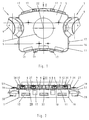
- the steering wheel switch is assembled State shown.
- An airbag module, not shown receiving carrier housing 1 is encircling Edge 16 provided.
- the carrier housing 1 has a center circular recess 2 through which a screw a steering wheel, not shown, with a not shown Steering column is accessible.
- a single switch 3 is attached, the comprises a two-part control element 4, which in its form the design of the steering wheel or airbag module, not shown is adjusted.
- On the back of the carrier housing 1 are threaded bores 5 receiving threaded bushings 8, into the distance screws 6 up to their distance stop 9 are screwed in.
- a contact unit 10 is arranged, the one with a side 11 on the back of the carrier housing 1 is present.
- On the metallic support plate 7 are in Inlay injection molding process four plastic tabs 13 attached, which a bearing for the spacer screws 6 and a pressure tappet 14 for actuating an assigned horn switch 15 form.
- At the peripheral edge 16 of the carrier housing 1 are plug-on elements 17 for fastening a covering the airbag module Baffle plate of a steering wheel or a steering wheel cover molded.
- the setting of the steering wheel switch in a steering wheel or on a steering wheel fixed carrier is carried out by means of Fastening or centering holes 18 of the support plate 7.
- the contact unit 10 has lateral bends 19, whose middle webs 21 are parallel to the contact unit 10 to the peripheral edge 16 in the direction of the carrier housing 1 extend.
- Each bend 19 carries a carrier housing 1 outstanding switch guide 20.
- the peripheral edge 16 of the Carrier housing 1, the central web 21 of the bend 19 and the switch guides 20 are parallel to the axis 22 of the steering column aligned.
- the support plate 7 comprises a central opening 23, the Edges 24 angled in the edge area for stiffening are.
- the opening 23 is provided with a shape 31, protrude through the connecting contacts 32 of the contact unit 10.
- the connection contacts 32 allow the supply to one Vehicle electrical system.
- the trapezoidal Part of the support plate comprises two opposite 90 ° Bends, the first bend 26 parallel to the axis 22 of the steering column and the second bend 27 perpendicular to first fold 26 runs.
- Cutouts 28 introduced, through the one hand screws 29 for fastening the individual switches 3 can be reached and on the other hand, free space for the arrangement of compression springs 30 is created which is the indirect reset of the horn switch 15 effect.
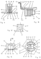
- FIG. 4 to 7 are different views of the contact unit 10 shown.
- the facing the carrier housing 1 Page 11 leaves in a contact unit 10 enveloping Plastic body 33 recesses 34, partially Connecting lines 35, 35a and the connecting lines 35 recognizing connecting webs 36.
- the shape of the separation points 34 is adapted to the position of the webs 36 to be separated, wherein the separation point 34 is round or elongated.
- In the top center is the back of the in a recess 37 in Plastic body 33 embedded connecting contacts 32 can be seen, those with the connecting lines 35 exposed there are laser welded (see Fig. 9).
- On the contact unit 10 is a switch guide 20 on the right and left the double extending in the direction of the steering wheel Angled 19 arranged.
- the plastic body 33 On the support plate 7 facing side 12 of the contact unit 10, the plastic body 33 also has separation points 34 on. In places where there is no separation of the Connecting lines 35, 35a takes place, but on which the connecting lines 35, 35a on both sides 11, 12 of the contact unit 10 exposed, there is a tool holder of the connecting lines 35, 35a during the extrusion coating. Furthermore, the connection contacts are at these points 32 or four domes each receiving a horn switch 15 37 arranged. Extend from the connection contacts 32 the connecting lines within the plastic body 33 35 up to the arranged in the switch guides 20 as Connector pins 38 trained switch contacts 39. In the course the connecting lines designed as lead frames 35, 35a form the four locations within each dome 37 exposed connecting lines 35, 35a contact points 40 for the horn switch 15. In one piece with the plastic body 33 of the contact unit 10, the position elements 41 are also implemented, each comprising a bore 51.
- the side walls 54 of the four domes 37 are molded on Provide clamping ribs 58, each of which by a compression spring 30 be attacked.
- the inner diameter of the compression spring 30 and the outward tips of the clamping ribs 58 are coordinated so that the compression spring 30th slightly jammed after being pushed onto cathedral 37.
- the carrier housing 1 between the individual switches 3 and the contact unit 10 is arranged.
- the support board 7 is by means of the spacer screws 6, the two holes 65 and the penetrate the middle free recess 66 of the contact unit 10 connected to the carrier housing 1.
- the compression springs 30 arranged with bias, so that a tumbling storage of the carrier housing 1 with the contact unit 10 fixed thereon on the support board 7 is guaranteed.
- connection lines 35, 35a without the bends 19 shown. For reasons of clarity, hatching is omitted.
- the connecting lines 35, 35a extend from the three connector pins 38 of the Terminal contacts 32, over the entire contact unit 10. In part, they end at the switch contacts 39, in each of which five connector pins 38 are arranged, partially run they continue from there and branch out. Some connecting lines 35a only run between the switch contacts 39 or between the switch contacts 39 and the contact points 40 for the horn switch 15. For each horn switch 15 are in the contact points 40 four areas of the connecting lines 35, 35a available for electrical connection.
- each contact point 40 is with insertion holes 42 for Fixation of the horn switch 15 provided when punching the connecting lines 35 or when spraying the contact unit 10 are manufactured. So that the lead frame one has a stable shape and can be handled as a part the webs 36 are present between the connecting lines 35.
- the connecting lines are held via these webs 36. After overmolding, depending on the electrical requirements, cutting the webs 36.
- FIG. 9 shows the connector pins 38 of the connection contacts 32.
- the side 11 of the contact unit facing the carrier housing 1 10 is provided with a thickening 43 in which the Formation 31 is embedded.
- the connecting lines 35, 35a to the side 11 are exposed.
- insertion holes 44 for the connector pins 38 are punched through which these are passed are.
- the connector pins 38 are within the formation 31 welded to the connecting lines 35, 35a.
- a Connector base 45 for mechanical mounting of the connector pins 38 molded onto this over a large part of its length holds.
- the one that protrudes freely beyond the connector base 45 Part of the connector pins 38 is a plug-in coding comprehensive plug collar 46 protectively surrounded.
- the switch guide 20 is over two bends 19 connected to the contact unit 10, wherein between the bend 19 and the switch guide 20 a the connecting lines 35, 35a exposed separation point 34 is arranged. Furthermore, the Connecting lines 35, 35a towards the side 12 of the Contact unit 10 in the area of the switch guide 20 in one Formation 47 free to weld the connector pins there 38 of the switch contact 39 with the connecting lines 35, 35a to enable.
- the connector pins 38 extend to the side 11 of the contact unit 10 into a collar 48 of the Switch guide 20, the two diagonally opposite bulges 49 as plug-in coding (see also Fig. 4). In the area of the bulges 49 are made of manufacturing technology For reasons of holes 50 admitted.
- the connector pins 38 in the switch guides 20 are opposite to the connector pins 38 of the contacts 32 aligned, whereby the contact unit is connected to the vehicle electrical system on the vehicle side and to the operator side with individual switches 3 is connected.
- the welding of the plug contacts 38 with The connecting lines 35 thus take place from both sides of the lead frame.
- each dome 37 is on the side 12 of the contact unit 10 the four circular and slotted domes 37 molded on, a recess in the area of the slot 67 53, in which the contact points 40 for the horn switch 15 exposed. From the side walls 54 of each dome 37 extend four inwardly directed guide ribs 55, between which the horn switch 15 with little play is recorded. Within the recess 53 there are 64 in the bottom of the cathedral, the two spaced, different diameters having insertion holes 42 through which a predetermined position of the horn switch 15 is made possible, since the horn switch 15 on its underside with corresponding Pin 56 is provided.
- buttons 57 of the horn switch 15 are below the upper edge of the Side walls 54 of the dome 37, whereby the horn switch 15 at assembly of the steering wheel switch protected from damage is.
- the buttons 57 are actuated by means of the Support plate 7 molded plunger 14, which in the dome 37th protrude into it.
- a cutout 61 places the lead frame free on both sides, so that the switch guide 20 two degrees of freedom having.
- An alternative execution show the 16 and 17.
- the cutout 61 is in a plane Area of the contact unit 10 incorporated.
- the connecting lines 35, 35a each have one from the level of the contact unit 10 bent out expansion loop 62, on the Degrees of freedom can be achieved in all levels. So that Connecting lines are in the area of the expansion loop 62 do not touch, are on the side 12 of the contact unit 10 Insulating washers 63 formed, which are higher than the expansion loop 62 and longer than the outbreak 61 are formed. The insulating washers 63 are on the side 12 of the contact unit 10 on, so that the contact unit 10 push together without jamming lets, and contacting the expansion loop 62nd is avoided.
- the individual switches 3 are between the spokes of the steering wheel for freely accessible and visible to the user. You are the one According to requirements as push button and / or latching switch executed.
- pressing the pushbutton and / or latching switch becomes a current path inside the steering wheel switch for a short time or permanently closed.
- the electrical signal is over the connecting lines 35, 35 a to the connection contacts 32 directed and fed from there to the electrical system.
- the electrical signal by means of coding elements, such as Resistors and the like are encoded.
- the operation of the horn switch 15 is done by depressing the airbag module overlapping baffle plate at any point in the direction the steering column.
- the carrier housing is attached to the airbag module 1 with a fixed contact unit 10 in the direction of Support board 7 moves against the action of the compression springs 30.
- the plunger 14 dips into the interior of the dome 37 and presses the button 57 of the horn switch 15.
- the Current path of the horn switch 15 Before the Dome 37 comes to rest on the support board 7, is the Current path of the horn switch 15 already closed, wherein the button 57 of the horn switch 15 when the dome 37 is on the support plate 7 has another free stroke.
- damage to the horn switch 15 is avoided since the high support force is not intercepted by the horn switch 15 must become.
- the horn switch 15 are the connecting lines 35, 35a of the lead frame assigned that, quite no matter which horn switch 15 is actuated, the current path for the horn operation is closed, and the horn signal sounds.
Landscapes
- Physics & Mathematics (AREA)
- Acoustics & Sound (AREA)
- Engineering & Computer Science (AREA)
- Mechanical Engineering (AREA)
- Push-Button Switches (AREA)
- Steering Controls (AREA)
- Air Bags (AREA)
Applications Claiming Priority (2)
| Application Number | Priority Date | Filing Date | Title |
|---|---|---|---|
| DE19819695 | 1998-05-02 | ||
| DE19819695A DE19819695C2 (de) | 1998-05-02 | 1998-05-02 | Lenkradschalter für ein Kraftfahrzeug |
Publications (3)
| Publication Number | Publication Date |
|---|---|
| EP0953480A2 true EP0953480A2 (fr) | 1999-11-03 |
| EP0953480A3 EP0953480A3 (fr) | 2001-03-21 |
| EP0953480B1 EP0953480B1 (fr) | 2003-08-20 |
Family
ID=7866521
Family Applications (1)
| Application Number | Title | Priority Date | Filing Date |
|---|---|---|---|
| EP99107919A Expired - Lifetime EP0953480B1 (fr) | 1998-05-02 | 1999-04-22 | Commutateur monté sur l'arbre de direction pour un véhicule |
Country Status (3)
| Country | Link |
|---|---|
| US (1) | US6147315A (fr) |
| EP (1) | EP0953480B1 (fr) |
| DE (2) | DE19819695C2 (fr) |
Cited By (2)
| Publication number | Priority date | Publication date | Assignee | Title |
|---|---|---|---|---|
| WO2004026639A1 (fr) * | 2002-09-16 | 2004-04-01 | Methode Electronics Inc. | Porte-contacts conçu pour etre integre dans un corps de volant de vehicule automobile |
| EP1623885A3 (fr) * | 2004-08-03 | 2007-07-18 | TRW Automotive Safety Systems GmbH | Module de coussin gonflable |
Families Citing this family (17)
| Publication number | Priority date | Publication date | Assignee | Title |
|---|---|---|---|---|
| JP2000331570A (ja) * | 1999-05-20 | 2000-11-30 | Alps Electric Co Ltd | ストークスイッチの取付構造 |
| JP4581244B2 (ja) * | 2000-01-14 | 2010-11-17 | タカタ株式会社 | エアバッグ装置及びステアリングホイール |
| JP3789284B2 (ja) * | 2000-04-28 | 2006-06-21 | アルプス電気株式会社 | 車両のハンドル用スイッチユニット |
| DE20016386U1 (de) * | 2000-09-21 | 2001-02-15 | TRW Automotive Safety Systems GmbH & Co. KG, 63743 Aschaffenburg | Gassack-Modul mit Multifunktions-Leiterfolie |
| US6510036B1 (en) * | 2000-11-28 | 2003-01-21 | Delphi Technologies, Inc. | Method and apparatus to eliminate inadvertent horn activation |
| DE20103890U1 (de) * | 2001-03-06 | 2001-07-12 | TRW Automotive Safety Systems GmbH & Co. KG, 63743 Aschaffenburg | Fahrzeuglenkrad |
| DE20105733U1 (de) * | 2001-04-02 | 2001-10-11 | TRW Automotive Safety Systems GmbH & Co. KG, 63743 Aschaffenburg | Schwingungsentkoppelt gelagerter Gasgenerator |
| US8301108B2 (en) * | 2002-11-04 | 2012-10-30 | Naboulsi Mouhamad A | Safety control system for vehicles |
| EP1446891B1 (fr) * | 2001-10-24 | 2013-08-21 | Mouhamad Ahmad Naboulsi | Systeme de controle de securite pour vehicules |
| US6731925B2 (en) * | 2001-10-24 | 2004-05-04 | Mouhamad Ahmad Naboulsi | Safety control system for vehicles |
| DE10209524B4 (de) * | 2002-03-04 | 2004-08-19 | Lisa Dräxlmaier GmbH | Elektrische Verkabelungsvorrichtung |
| DE10246113A1 (de) * | 2002-10-02 | 2004-04-22 | Siemens Ag | Deckel |
| DE10250457A1 (de) * | 2002-10-30 | 2004-05-19 | Delphi Technologies, Inc., Troy | Lenkrad eines Kraftfahrzeuges mit einem integrierten Airbagmodul |
| GB2400079B (en) * | 2003-04-02 | 2006-03-22 | Vertu Ltd | A mobile communication device and a cover for the same |
| US7029284B2 (en) * | 2003-11-17 | 2006-04-18 | Methode Electronics, Inc. | Floating contact assembly for a steering wheel |
| EP2390143B1 (fr) | 2010-05-31 | 2013-12-04 | Volvo Car Corporation | Agencement de connexion pour module d'airbag |
| DE112019002171B4 (de) * | 2018-05-30 | 2022-10-20 | Joyson Safety Systems Acquisition Llc | Integrierte elektronische Steuereinheit für eine Lenkradbaugruppe |
Family Cites Families (9)
| Publication number | Priority date | Publication date | Assignee | Title |
|---|---|---|---|---|
| DE1655117C3 (de) * | 1967-12-19 | 1973-11-29 | Swf-Spezialfabrik Fuer Autozubehoer Gustav Rau Gmbh, 7120 Bietigheim | Lenkstockschalter für Fahrzeuge, insbesondere fur Kraftfahrzeuge |
| DE2810790C3 (de) * | 1978-03-13 | 1980-10-09 | Adam Opel Ag, 6090 Ruesselsheim | Lenkstockschalter für Kraftfahrzeuge |
| US5331124A (en) * | 1992-07-20 | 1994-07-19 | Methode Electronics, Inc. | Wireless floating horn switch |
| US5333900A (en) * | 1992-12-04 | 1994-08-02 | Morton International, Inc. | Airbag cover retainer with wire retention feature and ground |
| US5303952A (en) * | 1992-12-23 | 1994-04-19 | United Technologies Automotive, Inc. | Electric signalling in a supplemental vehicle restraint system |
| US5627352A (en) * | 1994-09-28 | 1997-05-06 | Toyoda Gosei Co., Ltd. | Steering wheel |
| US5508482A (en) * | 1994-10-11 | 1996-04-16 | General Motors Corporation | Horn activation and steering wheel assembly |
| US5542694A (en) * | 1995-05-26 | 1996-08-06 | Larry J. Winget | Thermoplastic air bag cover having a unitary multifunctional domed switching module |
| SE9602747L (sv) * | 1996-07-11 | 1998-01-12 | Volvo Ab | Arrangemang vid fordonsratt |
-
1998
- 1998-05-02 DE DE19819695A patent/DE19819695C2/de not_active Expired - Fee Related
-
1999
- 1999-04-09 US US09/289,926 patent/US6147315A/en not_active Expired - Fee Related
- 1999-04-22 EP EP99107919A patent/EP0953480B1/fr not_active Expired - Lifetime
- 1999-04-22 DE DE59906633T patent/DE59906633D1/de not_active Expired - Lifetime
Cited By (2)
| Publication number | Priority date | Publication date | Assignee | Title |
|---|---|---|---|---|
| WO2004026639A1 (fr) * | 2002-09-16 | 2004-04-01 | Methode Electronics Inc. | Porte-contacts conçu pour etre integre dans un corps de volant de vehicule automobile |
| EP1623885A3 (fr) * | 2004-08-03 | 2007-07-18 | TRW Automotive Safety Systems GmbH | Module de coussin gonflable |
Also Published As
| Publication number | Publication date |
|---|---|
| EP0953480A3 (fr) | 2001-03-21 |
| DE19819695C2 (de) | 2000-12-07 |
| DE19819695A1 (de) | 1999-11-11 |
| DE59906633D1 (de) | 2003-09-25 |
| EP0953480B1 (fr) | 2003-08-20 |
| US6147315A (en) | 2000-11-14 |
Similar Documents
| Publication | Publication Date | Title |
|---|---|---|
| EP0953480B1 (fr) | Commutateur monté sur l'arbre de direction pour un véhicule | |
| EP1197402B1 (fr) | Volant de véhicule | |
| EP1181172B1 (fr) | Volant de direction | |
| DE102007000748A1 (de) | Spulenkörper für eine Stabantenne, Antenne und Türgriff für ein Fahrzeug | |
| DE19835459C2 (de) | Anschlußklemme für elektrische Leiter | |
| EP3116751B1 (fr) | Élément de connecteur pour fixer un module de coussin à gaz sur un volant, ensemble comportant d'un tel élément de connecteur et un manchon de positionnement ainsi que volant, module de coussin à gaz, ensemble volant et procédé de fabrication | |
| EP0258677B1 (fr) | Plaque support pour montage dans un moteur électrique | |
| DE3722069A1 (de) | Signalhornschaltvorrichtung fuer ein steuerrad | |
| EP1557852B1 (fr) | Volant de véhicule | |
| WO2013000804A1 (fr) | Dispositif de protection contre les surtensions | |
| WO2007113030A1 (fr) | Module de raccordement pour raccorder une unité de commande ou équivalent à une unité d'entraînement | |
| DE102008000224B4 (de) | Gassackmodul mit Hupvorrichtung | |
| EP1555865B1 (fr) | Assemblage d'un circuit bouchon avec des composants électroniques discrets et passifs | |
| DE69933155T2 (de) | Drehschalter | |
| EP1393973A2 (fr) | Dispositif de commande d'avertisseur sonore pour véhicule | |
| EP0412418B1 (fr) | Bouton de demande d'arrêt | |
| EP0410119B1 (fr) | Thermostat à mécanisme de commutation bimétallique | |
| DE3519303A1 (de) | Gleichspannungsgespeister naeherungsschalter | |
| EP1839322B1 (fr) | Connecteur a emboitement pour l'accouplement d'elements de commande de deux modules et appareil de commutation equipe dudit connecteur a emboitement | |
| EP1091376B1 (fr) | Interrupteur électrique à touche pivotante | |
| EP3576984B1 (fr) | Unité d'actionnement d'avertisseur sonore | |
| WO1999017960A1 (fr) | Commutateur basculant electrique | |
| EP0123040B1 (fr) | Plaque à bornes pour des appareils électriques ou électroniques, par exemple pour un interrupteur de protection contre la surintensité | |
| EP1467432A1 (fr) | Adaptateur de contact pour faire un contact à une structure d'antenne pour une voiture | |
| DE19614297C2 (de) | Elektrisches Installationsgerät |
Legal Events
| Date | Code | Title | Description |
|---|---|---|---|
| PUAI | Public reference made under article 153(3) epc to a published international application that has entered the european phase |
Free format text: ORIGINAL CODE: 0009012 |
|
| AK | Designated contracting states |
Kind code of ref document: A2 Designated state(s): DE ES FR GB IT |
|
| AX | Request for extension of the european patent |
Free format text: AL;LT;LV;MK;RO;SI |
|
| RIN1 | Information on inventor provided before grant (corrected) |
Inventor name: LANGE, ERHARD Inventor name: WEISS, HANS-GUENTER Inventor name: RUDOLPH, GERD |
|
| PUAL | Search report despatched |
Free format text: ORIGINAL CODE: 0009013 |
|
| AK | Designated contracting states |
Kind code of ref document: A3 Designated state(s): AT BE CH CY DE DK ES FI FR GB GR IE IT LI LU MC NL PT SE |
|
| AX | Request for extension of the european patent |
Free format text: AL;LT;LV;MK;RO;SI |
|
| RIC1 | Information provided on ipc code assigned before grant |
Free format text: 7B 60R 16/00 A, 7B 60R 21/20 B |
|
| 17P | Request for examination filed |
Effective date: 20010915 |
|
| AKX | Designation fees paid |
Free format text: DE ES FR GB IT |
|
| RAP1 | Party data changed (applicant data changed or rights of an application transferred) |
Owner name: DELPHI TECHNOLOGIES INC. |
|
| GRAH | Despatch of communication of intention to grant a patent |
Free format text: ORIGINAL CODE: EPIDOS IGRA |
|
| GRAS | Grant fee paid |
Free format text: ORIGINAL CODE: EPIDOSNIGR3 |
|
| GRAA | (expected) grant |
Free format text: ORIGINAL CODE: 0009210 |
|
| AK | Designated contracting states |
Designated state(s): DE ES FR GB IT |
|
| PG25 | Lapsed in a contracting state [announced via postgrant information from national office to epo] |
Ref country code: IT Free format text: LAPSE BECAUSE OF FAILURE TO SUBMIT A TRANSLATION OF THE DESCRIPTION OR TO PAY THE FEE WITHIN THE PRE;WARNING: LAPSES OF ITALIAN PATENTS WITH EFFECTIVE DATE BEFORE 2007 MAY HAVE OCCURRED AT ANY TIME BEFORE 2007. THE CORRECT EFFECTIVE DATE MAY BE DIFFERENT FROM THE ONE RECORDED.SCRIBED TIME-LIMIT Effective date: 20030820 |
|
| REG | Reference to a national code |
Ref country code: GB Ref legal event code: FG4D Free format text: NOT ENGLISH |
|
| REF | Corresponds to: |
Ref document number: 59906633 Country of ref document: DE Date of ref document: 20030925 Kind code of ref document: P |
|
| PG25 | Lapsed in a contracting state [announced via postgrant information from national office to epo] |
Ref country code: ES Free format text: LAPSE BECAUSE OF FAILURE TO SUBMIT A TRANSLATION OF THE DESCRIPTION OR TO PAY THE FEE WITHIN THE PRESCRIBED TIME-LIMIT Effective date: 20031201 |
|
| GBT | Gb: translation of ep patent filed (gb section 77(6)(a)/1977) |
Effective date: 20031224 |
|
| ET | Fr: translation filed | ||
| PLBE | No opposition filed within time limit |
Free format text: ORIGINAL CODE: 0009261 |
|
| STAA | Information on the status of an ep patent application or granted ep patent |
Free format text: STATUS: NO OPPOSITION FILED WITHIN TIME LIMIT |
|
| 26N | No opposition filed |
Effective date: 20040524 |
|
| PGFP | Annual fee paid to national office [announced via postgrant information from national office to epo] |
Ref country code: GB Payment date: 20100325 Year of fee payment: 12 |
|
| PGFP | Annual fee paid to national office [announced via postgrant information from national office to epo] |
Ref country code: FR Payment date: 20100521 Year of fee payment: 12 |
|
| PGFP | Annual fee paid to national office [announced via postgrant information from national office to epo] |
Ref country code: DE Payment date: 20100430 Year of fee payment: 12 |
|
| GBPC | Gb: european patent ceased through non-payment of renewal fee |
Effective date: 20110422 |
|
| REG | Reference to a national code |
Ref country code: FR Ref legal event code: ST Effective date: 20111230 |
|
| PG25 | Lapsed in a contracting state [announced via postgrant information from national office to epo] |
Ref country code: FR Free format text: LAPSE BECAUSE OF NON-PAYMENT OF DUE FEES Effective date: 20110502 |
|
| REG | Reference to a national code |
Ref country code: DE Ref legal event code: R082 Ref document number: 59906633 Country of ref document: DE Representative=s name: MUELLER, JOCHEN, DIPL.-ING., DE Ref country code: DE Ref legal event code: R082 Ref document number: 59906633 Country of ref document: DE Representative=s name: JOCHEN MUELLER, DE |
|
| PG25 | Lapsed in a contracting state [announced via postgrant information from national office to epo] |
Ref country code: GB Free format text: LAPSE BECAUSE OF NON-PAYMENT OF DUE FEES Effective date: 20110422 |
|
| REG | Reference to a national code |
Ref country code: DE Ref legal event code: R119 Ref document number: 59906633 Country of ref document: DE Effective date: 20111102 |
|
| PG25 | Lapsed in a contracting state [announced via postgrant information from national office to epo] |
Ref country code: DE Free format text: LAPSE BECAUSE OF NON-PAYMENT OF DUE FEES Effective date: 20111102 |