EP0953716A2 - Profilé d'écartement pour vitrage isolant - Google Patents
Profilé d'écartement pour vitrage isolant Download PDFInfo
- Publication number
- EP0953716A2 EP0953716A2 EP99108279A EP99108279A EP0953716A2 EP 0953716 A2 EP0953716 A2 EP 0953716A2 EP 99108279 A EP99108279 A EP 99108279A EP 99108279 A EP99108279 A EP 99108279A EP 0953716 A2 EP0953716 A2 EP 0953716A2
- Authority
- EP
- European Patent Office
- Prior art keywords
- metal foil
- spacer profile
- spacer
- profile according
- connecting web
- Prior art date
- Legal status (The legal status is an assumption and is not a legal conclusion. Google has not performed a legal analysis and makes no representation as to the accuracy of the status listed.)
- Granted
Links
- 125000006850 spacer group Chemical group 0.000 title claims description 91
- 239000011888 foil Substances 0.000 claims abstract description 93
- 229910052751 metal Inorganic materials 0.000 claims abstract description 91
- 239000002184 metal Substances 0.000 claims abstract description 91
- 239000004033 plastic Substances 0.000 claims abstract description 43
- 229920003023 plastic Polymers 0.000 claims abstract description 43
- 239000000463 material Substances 0.000 claims description 66
- 239000002274 desiccant Substances 0.000 claims description 55
- 230000002787 reinforcement Effects 0.000 claims description 25
- XEEYBQQBJWHFJM-UHFFFAOYSA-N Iron Chemical compound [Fe] XEEYBQQBJWHFJM-UHFFFAOYSA-N 0.000 claims description 23
- -1 polypropylene Polymers 0.000 claims description 17
- 239000004020 conductor Substances 0.000 claims description 14
- 239000004743 Polypropylene Substances 0.000 claims description 13
- 229920001155 polypropylene Polymers 0.000 claims description 13
- 229910052742 iron Inorganic materials 0.000 claims description 12
- 230000003014 reinforcing effect Effects 0.000 claims description 12
- 229910001220 stainless steel Inorganic materials 0.000 claims description 7
- 239000010935 stainless steel Substances 0.000 claims description 7
- 239000004698 Polyethylene Substances 0.000 claims description 4
- 229920000573 polyethylene Polymers 0.000 claims description 4
- 229920011250 Polypropylene Block Copolymer Polymers 0.000 claims description 3
- 238000001035 drying Methods 0.000 abstract 1
- 238000005452 bending Methods 0.000 description 28
- 238000004519 manufacturing process Methods 0.000 description 10
- 238000009792 diffusion process Methods 0.000 description 8
- IJGRMHOSHXDMSA-UHFFFAOYSA-N Atomic nitrogen Chemical compound N#N IJGRMHOSHXDMSA-UHFFFAOYSA-N 0.000 description 4
- 238000009413 insulation Methods 0.000 description 4
- 239000000126 substance Substances 0.000 description 4
- 230000004888 barrier function Effects 0.000 description 3
- 230000006735 deficit Effects 0.000 description 3
- 239000007789 gas Substances 0.000 description 3
- 239000003365 glass fiber Substances 0.000 description 3
- 238000007373 indentation Methods 0.000 description 3
- 239000000203 mixture Substances 0.000 description 3
- 230000000087 stabilizing effect Effects 0.000 description 3
- 239000000454 talc Substances 0.000 description 3
- 229910052623 talc Inorganic materials 0.000 description 3
- XKRFYHLGVUSROY-UHFFFAOYSA-N Argon Chemical compound [Ar] XKRFYHLGVUSROY-UHFFFAOYSA-N 0.000 description 2
- OKTJSMMVPCPJKN-UHFFFAOYSA-N Carbon Chemical compound [C] OKTJSMMVPCPJKN-UHFFFAOYSA-N 0.000 description 2
- VYZAMTAEIAYCRO-UHFFFAOYSA-N Chromium Chemical compound [Cr] VYZAMTAEIAYCRO-UHFFFAOYSA-N 0.000 description 2
- PWHULOQIROXLJO-UHFFFAOYSA-N Manganese Chemical compound [Mn] PWHULOQIROXLJO-UHFFFAOYSA-N 0.000 description 2
- XUIMIQQOPSSXEZ-UHFFFAOYSA-N Silicon Chemical compound [Si] XUIMIQQOPSSXEZ-UHFFFAOYSA-N 0.000 description 2
- 229910052782 aluminium Inorganic materials 0.000 description 2
- XAGFODPZIPBFFR-UHFFFAOYSA-N aluminium Chemical compound [Al] XAGFODPZIPBFFR-UHFFFAOYSA-N 0.000 description 2
- 230000015572 biosynthetic process Effects 0.000 description 2
- 229910052799 carbon Inorganic materials 0.000 description 2
- 230000000052 comparative effect Effects 0.000 description 2
- 230000000694 effects Effects 0.000 description 2
- 238000005516 engineering process Methods 0.000 description 2
- 239000011521 glass Substances 0.000 description 2
- 229910052748 manganese Inorganic materials 0.000 description 2
- 239000011572 manganese Substances 0.000 description 2
- 238000000034 method Methods 0.000 description 2
- 229910052757 nitrogen Inorganic materials 0.000 description 2
- 229920005629 polypropylene homopolymer Polymers 0.000 description 2
- 239000012744 reinforcing agent Substances 0.000 description 2
- 238000000926 separation method Methods 0.000 description 2
- 229910052710 silicon Inorganic materials 0.000 description 2
- 239000010703 silicon Substances 0.000 description 2
- OAICVXFJPJFONN-UHFFFAOYSA-N Phosphorus Chemical compound [P] OAICVXFJPJFONN-UHFFFAOYSA-N 0.000 description 1
- 229910018503 SF6 Inorganic materials 0.000 description 1
- ATJFFYVFTNAWJD-UHFFFAOYSA-N Tin Chemical compound [Sn] ATJFFYVFTNAWJD-UHFFFAOYSA-N 0.000 description 1
- 239000012963 UV stabilizer Substances 0.000 description 1
- 239000002318 adhesion promoter Substances 0.000 description 1
- 239000003570 air Substances 0.000 description 1
- 239000012080 ambient air Substances 0.000 description 1
- 229910052786 argon Inorganic materials 0.000 description 1
- QVGXLLKOCUKJST-UHFFFAOYSA-N atomic oxygen Chemical compound [O] QVGXLLKOCUKJST-UHFFFAOYSA-N 0.000 description 1
- 229920001400 block copolymer Polymers 0.000 description 1
- 239000003795 chemical substances by application Substances 0.000 description 1
- 229910052804 chromium Inorganic materials 0.000 description 1
- 239000011651 chromium Substances 0.000 description 1
- 239000002131 composite material Substances 0.000 description 1
- 238000010276 construction Methods 0.000 description 1
- 238000005336 cracking Methods 0.000 description 1
- 230000005489 elastic deformation Effects 0.000 description 1
- 238000001125 extrusion Methods 0.000 description 1
- 230000002349 favourable effect Effects 0.000 description 1
- 238000010438 heat treatment Methods 0.000 description 1
- 229920001519 homopolymer Polymers 0.000 description 1
- 230000001771 impaired effect Effects 0.000 description 1
- 229910052500 inorganic mineral Inorganic materials 0.000 description 1
- 238000009434 installation Methods 0.000 description 1
- 150000002505 iron Chemical class 0.000 description 1
- 229910052743 krypton Inorganic materials 0.000 description 1
- DNNSSWSSYDEUBZ-UHFFFAOYSA-N krypton atom Chemical compound [Kr] DNNSSWSSYDEUBZ-UHFFFAOYSA-N 0.000 description 1
- 150000002739 metals Chemical class 0.000 description 1
- 239000011707 mineral Substances 0.000 description 1
- 230000003287 optical effect Effects 0.000 description 1
- 229910052760 oxygen Inorganic materials 0.000 description 1
- 239000001301 oxygen Substances 0.000 description 1
- 229910052698 phosphorus Inorganic materials 0.000 description 1
- 239000011574 phosphorus Substances 0.000 description 1
- 230000019612 pigmentation Effects 0.000 description 1
- 229920000098 polyolefin Polymers 0.000 description 1
- 239000000843 powder Substances 0.000 description 1
- 239000000565 sealant Substances 0.000 description 1
- SFZCNBIFKDRMGX-UHFFFAOYSA-N sulfur hexafluoride Chemical compound FS(F)(F)(F)(F)F SFZCNBIFKDRMGX-UHFFFAOYSA-N 0.000 description 1
- 229960000909 sulfur hexafluoride Drugs 0.000 description 1
- 239000012815 thermoplastic material Substances 0.000 description 1
- 239000005028 tinplate Substances 0.000 description 1
- 229910052724 xenon Inorganic materials 0.000 description 1
- FHNFHKCVQCLJFQ-UHFFFAOYSA-N xenon atom Chemical compound [Xe] FHNFHKCVQCLJFQ-UHFFFAOYSA-N 0.000 description 1
Images

Classifications
-
- E—FIXED CONSTRUCTIONS
- E06—DOORS, WINDOWS, SHUTTERS, OR ROLLER BLINDS IN GENERAL; LADDERS
- E06B—FIXED OR MOVABLE CLOSURES FOR OPENINGS IN BUILDINGS, VEHICLES, FENCES OR LIKE ENCLOSURES IN GENERAL, e.g. DOORS, WINDOWS, BLINDS, GATES
- E06B3/00—Window sashes, door leaves, or like elements for closing wall or like openings; Layout of fixed or moving closures, e.g. windows in wall or like openings; Features of rigidly-mounted outer frames relating to the mounting of wing frames
- E06B3/66—Units comprising two or more parallel glass or like panes permanently secured together
- E06B3/663—Elements for spacing panes
- E06B3/66309—Section members positioned at the edges of the glazing unit
- E06B3/66314—Section members positioned at the edges of the glazing unit of tubular shape
- E06B3/66319—Section members positioned at the edges of the glazing unit of tubular shape of rubber, plastics or similar materials
-
- E—FIXED CONSTRUCTIONS
- E06—DOORS, WINDOWS, SHUTTERS, OR ROLLER BLINDS IN GENERAL; LADDERS
- E06B—FIXED OR MOVABLE CLOSURES FOR OPENINGS IN BUILDINGS, VEHICLES, FENCES OR LIKE ENCLOSURES IN GENERAL, e.g. DOORS, WINDOWS, BLINDS, GATES
- E06B3/00—Window sashes, door leaves, or like elements for closing wall or like openings; Layout of fixed or moving closures, e.g. windows in wall or like openings; Features of rigidly-mounted outer frames relating to the mounting of wing frames
- E06B3/66—Units comprising two or more parallel glass or like panes permanently secured together
- E06B3/663—Elements for spacing panes
- E06B3/66309—Section members positioned at the edges of the glazing unit
- E06B3/66314—Section members positioned at the edges of the glazing unit of tubular shape
-
- E—FIXED CONSTRUCTIONS
- E06—DOORS, WINDOWS, SHUTTERS, OR ROLLER BLINDS IN GENERAL; LADDERS
- E06B—FIXED OR MOVABLE CLOSURES FOR OPENINGS IN BUILDINGS, VEHICLES, FENCES OR LIKE ENCLOSURES IN GENERAL, e.g. DOORS, WINDOWS, BLINDS, GATES
- E06B3/00—Window sashes, door leaves, or like elements for closing wall or like openings; Layout of fixed or moving closures, e.g. windows in wall or like openings; Features of rigidly-mounted outer frames relating to the mounting of wing frames
- E06B3/66—Units comprising two or more parallel glass or like panes permanently secured together
- E06B3/663—Elements for spacing panes
- E06B3/66309—Section members positioned at the edges of the glazing unit
- E06B3/66328—Section members positioned at the edges of the glazing unit of rubber, plastics or similar materials
-
- E—FIXED CONSTRUCTIONS
- E06—DOORS, WINDOWS, SHUTTERS, OR ROLLER BLINDS IN GENERAL; LADDERS
- E06B—FIXED OR MOVABLE CLOSURES FOR OPENINGS IN BUILDINGS, VEHICLES, FENCES OR LIKE ENCLOSURES IN GENERAL, e.g. DOORS, WINDOWS, BLINDS, GATES
- E06B3/00—Window sashes, door leaves, or like elements for closing wall or like openings; Layout of fixed or moving closures, e.g. windows in wall or like openings; Features of rigidly-mounted outer frames relating to the mounting of wing frames
- E06B3/66—Units comprising two or more parallel glass or like panes permanently secured together
- E06B3/663—Elements for spacing panes
- E06B3/66309—Section members positioned at the edges of the glazing unit
- E06B3/66361—Section members positioned at the edges of the glazing unit with special structural provisions for holding drying agents, e.g. packed in special containers
-
- E—FIXED CONSTRUCTIONS
- E06—DOORS, WINDOWS, SHUTTERS, OR ROLLER BLINDS IN GENERAL; LADDERS
- E06B—FIXED OR MOVABLE CLOSURES FOR OPENINGS IN BUILDINGS, VEHICLES, FENCES OR LIKE ENCLOSURES IN GENERAL, e.g. DOORS, WINDOWS, BLINDS, GATES
- E06B3/00—Window sashes, door leaves, or like elements for closing wall or like openings; Layout of fixed or moving closures, e.g. windows in wall or like openings; Features of rigidly-mounted outer frames relating to the mounting of wing frames
- E06B3/66—Units comprising two or more parallel glass or like panes permanently secured together
- E06B3/663—Elements for spacing panes
- E06B3/66309—Section members positioned at the edges of the glazing unit
- E06B2003/6638—Section members positioned at the edges of the glazing unit with coatings
-
- E—FIXED CONSTRUCTIONS
- E06—DOORS, WINDOWS, SHUTTERS, OR ROLLER BLINDS IN GENERAL; LADDERS
- E06B—FIXED OR MOVABLE CLOSURES FOR OPENINGS IN BUILDINGS, VEHICLES, FENCES OR LIKE ENCLOSURES IN GENERAL, e.g. DOORS, WINDOWS, BLINDS, GATES
- E06B3/00—Window sashes, door leaves, or like elements for closing wall or like openings; Layout of fixed or moving closures, e.g. windows in wall or like openings; Features of rigidly-mounted outer frames relating to the mounting of wing frames
- E06B3/66—Units comprising two or more parallel glass or like panes permanently secured together
- E06B3/663—Elements for spacing panes
- E06B3/66309—Section members positioned at the edges of the glazing unit
- E06B2003/66395—U-shape
Definitions
- the present invention relates to a spacer profile for a spacer frame, the in the edge area of an insulating pane unit to form a space between the panes is attached, with a profile body made of a poorly heat-conducting plastic material and with a diffusion-proof metal foil that is integrally connected to the profile body is.
- the invention relates in particular to spacer profiles of the aforementioned type, the profile body Landing ridges for contacting the inside of the insulating pane unit and has a connecting web bridging the space between the panes when installed, are connected to each other by the at least two jetties, the Spacer profile also a desiccant chamber arranged between the contact webs comprises, and wherein the metal foil substantially over the entire width of the spacer profile extends and with the chamber-side surfaces of the landing stages as well as with itself adjoining end pieces of the connecting web are integrally connected.
- the profile body of the spacer profile made of poorly heat-conducting plastic material comprises the bulk of the main part of the spacer profile and gives this be Cross-sectional profile.
- the washers of the insulating washer are normal within the scope of the invention Glass panes made of inorganic or organic glass, but without the invention would be limited to this.
- the panes can be coated or otherwise refined, around the insulating pane unit special functions such as increased thermal insulation or Soundproofing.
- thermal conductivity values ⁇ are typically of the order of 5 W / (m ⁇ K) and below, preferably they are less than 1 W / (m ⁇ K) and more preferably less than 0.3 W / (m ⁇ K).
- plastics generally have a low diffusion tightness compared to metal on.
- spacer profiles made of plastic special measures must be taken ensure that the air humidity in the area is not in the The space between the panes penetrates to such an extent that the capacity of the spacer profiles usually placed desiccant is soon exhausted and the Insulating pane unit is impaired in its functionality.
- a spacer profile must also be used also prevent fill gases from the space between the panes, such as Argon, krypton, xenon, sulfur hexafluoride, escape from this. Vice versa nitrogen, oxygen, etc. contained in the ambient air should not enter the space between the panes enter.
- diffusion tightness this means both vapor diffusion tightness and gas diffusion tightness for the named Gases.
- DE 33 02 659 A1 proposes to improve the vapor diffusion tightness Spacer profile made of plastic with a vapor barrier by the Plastic profile on the surface which, when installed, from The space between the panes is turned away, a thin metal foil or a metallized plastic foil is applied. This metal foil must completely cover the space between the panes span so that the desired vapor barrier effect occurs.
- spacer profiles are preferably used as one-piece spacer frames manufactured, which are bent at three or four corners and where the connection of the End pieces via a corner connector or a straight connector inserted into the end pieces he follows.
- the aim here is to make corner bending as simple as possible in terms of production technology to be carried out, in particular without extensive prior heating.
- spacer profiles In order to enable cold-bendability of spacer profiles made of poorly heat-conducting materials, spacer profiles have been developed in which the profile body made of poorly heat-conductive, elastically-plastically deformable material is integrally bonded to a plastically deformable reinforcing layer, preferably a metal foil.
- This reinforcement layer can also be made diffusion-tight and span the entire width of the inter-pane space, as a result of which the required diffusion-tightness of the spacer profile is achieved.
- Such a spacer profile was presented under the name THERMOPLUS ® TIS ®, for example in the brochure "Impulses for the future" from Flachglas AG and is described in the priority utility model DE 298 14 768 U1.
- a polyropylene homopolymer with an elastic modulus (E-modulus) of 1900 N / mm 2 is used for the profile body, while the reinforcement layer is either made of less than 0.2 mm thick iron sheet or less than 0.1 mm thick stainless steel.
- the side walls of the desiccant chamber give the profile according to the state of the Technology a comparatively high bending resistance moment, so that it is during the cold bending process to uncontrolled bulges of the side walls in the direction of the jetties or to undesirable deformations of the connecting web can occur.
- the present invention is based on the object of producing an inexpensive one
- To provide spacer profile that is used to achieve good thermal insulation has a profile body made of poorly heat-conducting material to ensure a sufficient diffusion tightness is provided with a metal foil and in which the Cold bendability is further improved compared to the previously known profile, wherein undesirable deformations of the profile body, in particular the connecting web, and Cracks in the metal foil as well as disruptive foil detachments also high during cold bending stressed profile areas should be reliably avoided.
- the walls of the formed from the metal foil Desiccant chamber deform from the profile according to the prior art DE 298 14 768 U1 lighter and over a longer profile section, so that the risk of Tear of the metal foil when bending is significantly reduced. It is understood that the thickness of the Metal foil must not be chosen too large, so that the desired good deformability of the walls of the desiccant chamber formed by the metal foil is reached. In practice you will choose the film thickness as small as possible, so that there is still sufficient Diffusion tightness is maintained, the walls of the chamber are still crack-free survive and the heat conduction through the profile is as low as possible.
- the spacer profile according to the invention it is therefore possible to achieve the the cold bendability, in addition to the contact bars, is a particularly critical area of the previously known teaching in the profile body integrated desiccant chamber from the Structural separation of the profile body, so to speak, so that none during the bending process excessive deformation forces on the connecting web from poorly heat-conducting Material or impact on the piers.
- all are also Walls of the desiccant chamber other than that of a central part of the connecting web formed inner wall formed by the metal foil, but different from the first Embodiment one or more of these walls with a thin reinforcement layer poorly conductive material are provided, the thickness of which is a maximum of 50% of the thickness of the Connecting web is.
- An elastically-plastically deformable is preferred Material, especially a plastic material used.
- the reinforcement layer of the chamber walls is like this small dimensions so that the metal foil remains sufficiently easily deformable and that disruptively high deformation forces on the connecting web when bending the profile be avoided.
- a thin reinforcement layer e.g. be achieved that the desiccant chamber is not already when handling the profile deformed or specifically the deformation of the chamber walls when cold-bending the profile is controlled.
- the thickness of the reinforcement layer is small in the region of a or more of the chamber walls formed from the metal foil which are associated with of the first embodiment mentioned structural separation of the profile body from the Desiccant chamber largely preserved.
- the desiccant chamber of the invention preferably has Profiles on two side walls that are substantially parallel to the adjacent landing stages run, as well as at least one facing away from the space between the panes in the installed state Outer wall that runs essentially parallel to the connecting web.
- the contact webs connected to the metal foil those connected to the metal foil End pieces of the connecting web and the neighboring ones formed by the metal foil
- Sidewalls of the desiccant chamber in cross-section each in the installed state Outer edge of the insulating washer unit open U-shape.
- the Sidewalls of the desiccant chamber with a thin reinforcement layer made of bad provided heat-conducting material This can cause unwanted bulges of the Side walls during cold bending can be avoided, but without being undesirably high Deformation forces on the connecting web comes.
- the thickness of the reinforcement layer Side walls are preferably less than a third, more preferably less than one Quarter of the thickness of the connecting web.
- the one facing away from the space between the panes is in the installed state Outside wall of the desiccant chamber with a reinforcement layer made of bad provided heat-conducting material.
- This measure can increase the stability of the Profile can be achieved when handling, without the thickness of the metal foil and thus the heat conduction through the profile would have to be increased.
- Even the thickness of the Reinforcing layer of the outer wall is preferably less than a third, further preferably less than a quarter of the thickness of the connecting web.
- the reinforcement layer covers the metal foil at least in some areas on both sides, so that the metal foil in these areas in the Reinforcement layer is embedded as it were, but care must be taken that the Thickness of the reinforcement layer in these areas as a whole not more than 50% of the The thickness of the connecting web is not too great, in order not to increase the rigidity of the chamber walls increase.
- By embedding the metal foil in the reinforcement layer from bad Heat-conducting (plastic) material can be used in particularly vulnerable areas mechanical or chemical impairments are protected. Besides, can this affects the optical appearance of the spacer profile in a targeted manner.
- the spacer profile according to the invention is preferably produced so that the metal foil according to the desired cross-sectional shape with formation of the walls of the Desiccant chamber is deformed. Subsequently, the profile body, i.e. the Connecting bridge, the landing stages and - if provided - the reinforcement layer, forming thermoplastic material by extrusion on the preformed Metal foil applied, creating a cohesive connection between the two Forms components.
- the desired cold bending behavior can also be achieved by a specific one Setting the stiffness of the plastic material of the profile body can be achieved.
- a third aspect provides that, at least for parts of the profile body adjacent to the metal foil, a plastic material with a flexural modulus (according to DIN 53457) of less than 1,900 N / mm 2 , in particular less than 1,500 N / mm 2 , is used. It can be achieved in this way that the metal foil adjoins a relatively soft and easily deformable material, at least in the areas particularly prone to cracking, so that local stress peaks during cold bending are avoided.
- the entire profile body is preferably made entirely of a plastic material with a flexural modulus set according to the invention, which simplifies production and reduces the production costs.
- parts of the profile such as an inner wall of the profile adjacent to the space between the panes (the connecting web) from a more rigid material in order to give the profile a higher rigidity. This can be done, for example, by using another plastic material with a higher flexural modulus or by adding conventional reinforcing agents in certain areas to the plastic material used according to the invention, these reinforcing agents preferably being glass fibers. Materials known from the prior art can be used here.
- EP 0 745 470 A1 discloses a homogeneous profile rod which can also be used as a spacer profile for insulating pane units and which consists of a polyolefin with incorporated glass fibers. E-module values of 5500 N / mm 2 and above are achieved.
- a spacer profile for insulating pane units is also known from EP 0 127 739 B1, which consists of a polypropylene filled with glass fibers or mineral powder.
- the profile body is arranged approximately parallel to the plane of the pane, with the Walls connected to metal foil, but especially for the landing stages, according to the invention set plastic material to use and less mechanically during cold bending claimed rest of the profile body made of a material with a higher flexural modulus manufacture.
- the plastic material preferably has a yield strength (according to DIN EN ISO 527-1) of less than 38 N / mm 2 , preferably at most 30 N / mm 2 , and an elongation at break (according to DIN EN ISO 527-1) of more than 7%, preferably at least 8%
- the spacer profile Due to the low bending modulus of elasticity used for the profile body or parts thereof Plastic material and the associated low yield strength or high Elongation at break of this material, the spacer profile is better overall and under Avoiding local voltage peaks deformable, so that the risk of detachment or even Tear of the metal foil during cold bending is significantly reduced.
- the stiffness the spacer profile through the integral connection of the metal foil with the Profile body despite its low flexural modulus when using a suitable profile geometry are held so high that undesired deformations of the spacer profile, especially in the area of jetties, can be avoided during cold bending.
- the flexural modulus should not fall below a value of 900 N / mm 2 , so that the overall rigidity of the profile is still sufficiently high.
- the sandwich composite of profile body and has plastic material Metal foil for both the easy manufacture of one-piece spacer frames required mechanical properties (cold bendability) as well as those for use in Insulating washer units required high diffusion tightness and low thermal conductivity on.
- plastic materials for realizing the invention preferably comprise The main component is polypropylene.
- Polyropylene block copolymers are particularly preferred, especially those with grafted polypropylene or polyethylene.
- This Material group has a particularly favorable range of properties in connection with the the object underlying the invention.
- the material preferred for the profile body according to the invention is generally suitable for Production of a profile, the profile body of which is a hollow profile with a rectangular cross section comprises a chamber for receiving desiccant. It is understood that the Chamber for establishing a gas-conducting connection with the space between the panes Perforations or the like in the inner wall facing the space between the panes must have.
- this aspect of the invention can be used with particular advantage in Spacer profiles according to DE 298 14 768 U1.
- the profile body points in this case Landing ridges for planting on the inside of a pane, which over the bridge sections a desiccant chamber are connected.
- the metal foil is with the contact surface Contact webs, the surface of the surface facing away from the space between the panes Bridge sections and the outer surfaces of the walls of the desiccant chamber cohesively connected.
- the metal foil at least on a part of the inner side of the pane facing the installed state Contact surfaces of the jetties is arranged. This will increase the stability of the Landing ridges during cold bending and good adhesion to the sealant achieved.
- the thickness of the metal foil is preferably between 0.02 mm and 0.3 mm, particularly preferably between 0.1 mm and 0.15 mm, while the thickness of the connecting web is preferably between 0.5 mm and 1.5 mm. This dimensioning of the main components
- the spacer profile according to the invention has proven itself to be a good one To give cold bendability when using common materials and the profile to be able to produce inexpensively.
- Suitable materials for the metal foil are in particular stainless steel or chrome or tinned iron sheet, the thickness of the metal foil being at most 0.2 mm and at least 0.05 mm, in the case of iron sheet at least 0.1 mm.
- Preferred values for the thickness of the metal foil for stainless steel are approximately 0.08-0.1 mm and for iron sheet about 0.1 - 0.13 mm.
- Figures 1 to 5 show cross-sectional views of the invention Spacer profiles. Apart from manufacturing tolerances changes this cross-section normally extends over the entire length of a spacer profile Not.
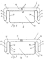
- Figure 1 shows a first embodiment of a spacer profile according to the first variant of the present invention.
- the profile body comprises two abutment webs 10 for abutment on the inside of each pane of an insulating pane unit and a connecting web 20 which connects the abutment webs 10 to one another and bridges the space between the panes in the installed state.
- the profile body was produced from black-colored polypropylene Novolen 1040 K with a thickness of 1 mm.
- materials 1 or 2 according to the third aspect of the invention, which are described in more detail below, are preferably used.
- a chrome-plated iron sheet foil with a thickness of 0.125 mm was used as the metal foil 40 used.
- the metal foil 40 is on the free edges of the contact webs 10 and on the chamber-side surfaces 11 of the contact webs 10 and on the adjoining them End pieces (bridge webs) 21 of the connecting web 20 are laminated on.
- a middle piece 22 of the connecting web 20 the metal foil 40 is at a distance from Connecting web 20 is arranged, whereby a cavity is formed, which as Desiccant chamber 30 can be used.
- the middle piece 22 of the Connecting web 20 the inner wall of the desiccant chamber 30, while the metal foil 40 the three other walls 32, 34, 36 of the desiccant chamber 30, one in the has an essentially rectangular cross section.
- the middle piece 22 of the connecting web 20 is in the region of the desiccant chamber 30 Perforations 23 provided so that moisture from the interior of the in the installed state Insulating pane unit through the desiccant introduced into the desiccant chamber 30 (not shown) can be included.
- FIG. 2 shows a second embodiment of a spacer profile according to the invention in cross section.
- the profile body made again from polypropylene novolen 1040 K in the example, consists of contact webs 10 and a connecting web 20, two thin reinforcement layers 50 extending from the ends of the middle piece 22 of the connecting web 20, which are connected to the inner surfaces 51 of the side walls 32, 34 Desiccant chamber 30 are connected and which also consist of polypropylene Novolen 1040 K.
- the metal foil 40 is laminated on the edges of the contact webs 10 and on the chamber-side surfaces 11 of the contact webs 10 and the adjoining end pieces 21 of the connecting web 20 and also forms the outer wall 36 and the side walls 32, 34 of the desiccant chamber adjoining it at a right angle 30th
- the reinforcing layers 50 stabilizing the side walls 32, 34 have a thickness of about 0.25 mm, which is about a quarter of the thickness of the profile body, ie the thickness of the Connecting web 20 and the landing stages 10 corresponds.
- a tin-plated iron sheet (tinplate) was used as an example as metal foil 40 a thickness of 0.125 mm was used.
- a tin layer with a basis weight of 2.8 g / m 2 was applied to the sheet, which corresponds to a thickness of 0.38 ⁇ m.
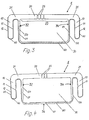
- FIG. 3 a further embodiment of a spacer profile according to the invention is shown in cross section.
- a drying agent chamber 30 formed from a metal foil 40 and the middle piece 22 of the connecting web 20 is connected to the profile body consisting of the contact webs 10 and the connecting web 20, the side walls 32, 34 of which are provided with thin stabilizing reinforcing layers 50 and the outer wall 36 of which is provided with a further thin stabilizing reinforcing layer 60 are connected.
- All reinforcement layers 50, 60 were in the example shown as that Profile body made of polypropylene Novolen 1040 K. They had a thickness of 0.15 mm, which corresponded to approximately 15% of the thickness of the connecting web 20.
- metal foil 40 a stainless steel foil with a thickness of 0.05 mm was used. She was on the im Installation state of the contact surfaces 12 of the contact webs 10 facing the inside of the pane, the edges of the contact webs 10, the chamber-side surfaces 11 of the contact webs 10 and the adjoining end pieces 21 of the connecting web 20 are laminated on and formed furthermore, as mentioned, the side walls 32, 34 and the outer wall 36 of the Desiccant chamber 30.
- the chemical composition of the stainless steel used for the metal foil 40 was (in Weight percent):
- FIG. 4 shows a further embodiment of a spacer profile according to the invention, which differs from the embodiment shown in FIG. 3 in that the reinforcing layer 60 connected to the outer wall 36 of the drying agent chamber 30 formed by the metal foil 40 is arranged on the outside of the outer wall 36, as a result of which it is better protected against mechanical and chemical impairments.
- Figure 5 shows a fifth embodiment of a spacer profile according to the invention with a profile body according to DE 298 14 768 U1.
- a desiccant chamber 30 is defined by walls 32, 34, 36 and the middle piece 22 of the connecting web 20, the gas-conducting connection being established between this chamber 30 and the space between the panes via passage openings 23.
- end pieces 21 of the connecting web 20 form bridge sections between the desiccant chamber 30 and contact webs 10, the contact webs 10 each having an indentation 70 in their surfaces facing the inside of the pane in the installed state, into which a metal foil 40 is inserted.
- the depth of the indentation 70 corresponds exactly to the thickness of the metal foil 40, so that the contact surface formed by the profile body 1 and the contact surface formed by the metal foil 40 lie exactly in one plane.
- the profile form shown is the subject of the earlier priority utility model application DE 298 07 418.4, the content of which is referred to in full in order to avoid repetitions.
- the metal foil 40 essentially extends from the contact surface of the first contact web 10 around it to the first end piece 21, then around the chamber 30 to the second end piece 21 and around the second contact web 10 up to its contact surface.
- a 0.125 mm thick chromed iron sheet with an adhesion promoter layer was used for the diffusion-tight metal foil 40 which is integrally connected to the profile body 1.
- Such a diffusion-proof sheet iron sheet is the subject of the earlier priority utility model application DE 298 07 413.3, to which reference is also expressly made.
- a stainless steel can also be used, in which case the thickness is preferably between 0.08 and 0.1 mm. Regardless of the material, the aim should be that the elongation at break of the metal foil 40 used before the deformation and connection to the profile body 1 is more than 15%.
- the plastic materials also each contained 1% by weight of a suitable color batch (black pigmentation) and 2% by weight of a UV stabilizer.
- the plastic materials had the mechanical properties shown in the following table: Measurand Material 1 Material 2 Comparative material Bending modulus of elasticity (DIN 53457) 1180 N / mm 2 1280 N / mm 2 2083 N / mm 2 Elongation at stretch (DIN EN 527-1) 9.4% 8.8% 3.9% Yield strength (DIN EH ISO 527-1) 24.8 N / mm 2 26.3 N / mm 2 34.8 N / mm 2 Elongation at break (DIN EH ISO 527) > 800% > 750% 4.1%
- the spacer profile according to FIG. 5 was closed in a commercial bending machine a rectangular spacer frame cold bent. It deformed Use of materials 1 and 2 in the area of the corners as desired, without cracks in the Metal foil 40, foil detachments or other disruptive deformations, especially in the area the pier 10 occurred.
- the comparison material which has a significantly higher flexural modulus had and also in terms of yield strength, elongation at break and elongation at break clearly differed from materials 1 and 2 because of the occurrence of cracks in the metal foil 40 as unusable.
Landscapes
- Engineering & Computer Science (AREA)
- Structural Engineering (AREA)
- Civil Engineering (AREA)
- Architecture (AREA)
- Securing Of Glass Panes Or The Like (AREA)
- Joining Of Glass To Other Materials (AREA)
- Laminated Bodies (AREA)
- Insulating Bodies (AREA)
- Insulators (AREA)
- Bolts, Nuts, And Washers (AREA)
Applications Claiming Priority (4)
| Application Number | Priority Date | Filing Date | Title |
|---|---|---|---|
| DE29807419U | 1998-04-27 | ||
| DE29807419U DE29807419U1 (de) | 1998-04-27 | 1998-04-27 | Abstandhalterprofil für Isolierscheibeneinheit |
| DE1998159866 DE19859866A1 (de) | 1998-12-23 | 1998-12-23 | Abstandhalterprofil für Isolierscheibeneinheit |
| DE19859866 | 1998-12-23 |
Publications (3)
| Publication Number | Publication Date |
|---|---|
| EP0953716A2 true EP0953716A2 (fr) | 1999-11-03 |
| EP0953716A3 EP0953716A3 (fr) | 2000-11-02 |
| EP0953716B1 EP0953716B1 (fr) | 2005-03-09 |
Family
ID=26051020
Family Applications (1)
| Application Number | Title | Priority Date | Filing Date |
|---|---|---|---|
| EP99108279A Expired - Lifetime EP0953716B1 (fr) | 1998-04-27 | 1999-04-27 | Profilé d'écartement pour vitrage isolant |
Country Status (5)
| Country | Link |
|---|---|
| US (1) | US6250045B1 (fr) |
| EP (1) | EP0953716B1 (fr) |
| AT (1) | ATE290641T1 (fr) |
| CA (1) | CA2269110A1 (fr) |
| DE (1) | DE59911717D1 (fr) |
Cited By (3)
| Publication number | Priority date | Publication date | Assignee | Title |
|---|---|---|---|---|
| WO2008017590A1 (fr) * | 2006-08-11 | 2008-02-14 | Rolltech A/S | Espaceur pour former un espacement entre des carreaux de verre et procédé de fabrication d'un tel espaceur |
| EP1860270A3 (fr) * | 2006-05-24 | 2010-03-24 | Peter Lisec | Unité de verre isolant dotée d'une bande de retenue d'écart élastoplastique et procédé d'application de cette dernière |
| DE102012105960A1 (de) * | 2012-07-04 | 2014-01-09 | Ensinger Gmbh | Abstandhalter fuer Isolierglasscheiben |
Families Citing this family (20)
| Publication number | Priority date | Publication date | Assignee | Title |
|---|---|---|---|---|
| US6367223B1 (en) | 2000-06-09 | 2002-04-09 | Anthony, Inc. | Display case frame |
| DE202005019973U1 (de) * | 2004-09-09 | 2006-04-06 | Technoform Caprano Und Brunnhofer Gmbh & Co. Kg | Abstandshalterprofil für einen Abstandshalterrahmen für eine Isolierscheibeneinheit und Isolierscheibeneinheit |
| US20070227097A1 (en) * | 2006-03-15 | 2007-10-04 | Gallagher Raymond G | Composite spacer bar for reducing heat transfer from a warm side to a cold side along an edge of an insulated glazing unit |
| US20080053037A1 (en) * | 2006-08-29 | 2008-03-06 | Gallagher Raymond G | System and method for reducing heat transfer from a warm side to a cold side along an edge of an insulated glazing unit |
| US20100031591A1 (en) * | 2007-03-15 | 2010-02-11 | Gallagher Raymond G | Composite spacer bar for reducing heat transfer from a warm side to a cold side along an edge of an insulated glazing unit |
| DE102008033249A1 (de) * | 2008-07-15 | 2010-01-21 | Gssg Holding Gmbh & Co. Kg | Isolierglasscheibe |
| WO2011088994A2 (fr) * | 2010-01-20 | 2011-07-28 | Technoform Glass Insulation Holding Gmbh | Agrafe de bord composite pour unité en verre isolant, bord composite d'une unité en verre isolant, unité de verre isolant doté d'une agrafe de bord composite et écarteur pour unité en verre isolant |
| DE102010049806A1 (de) * | 2010-10-27 | 2012-05-03 | Technoform Glass Insulation Holding Gmbh | Abstandshalterprofil und Isolierscheibeneinheit mit einem solchen Abstandshalterprofil |
| DE102011009359A1 (de) | 2011-01-25 | 2012-07-26 | Technoform Glass Insulation Holding Gmbh | Abstandshalterprofil und Isolierscheibeneinheit mit einem solchen Abstandshalterprofil |
| DE202012013491U1 (de) * | 2012-01-13 | 2017-02-24 | Saint-Gobain Glass France | Abstandshalter für Isolierverglasungen |
| EP2626496A1 (fr) | 2012-02-10 | 2013-08-14 | Technoform Glass Insulation Holding GmbH | Profil d'espaceur pour cadre d'espaceur pour une unité de verre isolant avec éléments d'intervalle et unité de verre isolant |
| JP6419168B2 (ja) * | 2013-09-30 | 2018-11-07 | サン−ゴバン グラス フランスSaint−Gobain Glass France | 複層ガラス用のスペーサ |
| WO2015086457A2 (fr) | 2013-12-12 | 2015-06-18 | Saint-Gobain Glass France | Vitrage isolant à étanchéité améliorée |
| EP3080376A1 (fr) | 2013-12-12 | 2016-10-19 | Saint-Gobain Glass France | Entretoises pour vitrages isolants comportant un profilé d'étanchéité extrudé |
| TR201815606T4 (tr) | 2014-06-27 | 2018-11-21 | Saint Gobain | Mesafe parçasına sahip yalıtım cam kaplaması ve bunun imal edilmesi için yöntem ve ayrıca bunun bina cam kaplaması olarak kullanımı. |
| US10301868B2 (en) | 2014-06-27 | 2019-05-28 | Saint-Gobain Glass France | Insulated glazing comprising a spacer, and production method |
| EP3421709B2 (fr) | 2014-09-25 | 2022-11-30 | Saint-Gobain Glass France | Entretoise pour vitrages isolants |
| MX2017011083A (es) | 2015-03-02 | 2017-11-10 | Saint Gobain | Separador reforzado con fibra de vidrio para unidad de acristalamiento aislante. |
| USD777345S1 (en) | 2015-05-21 | 2017-01-24 | Saint-Gobain Glass France | Spacer bar |
| DE102016115023A1 (de) * | 2015-12-23 | 2017-06-29 | Ensinger Gmbh | Abstandhalter für Isolierglasscheiben |
Citations (4)
| Publication number | Priority date | Publication date | Assignee | Title |
|---|---|---|---|---|
| DE3302659A1 (de) | 1983-01-27 | 1984-08-02 | Reichstadt, Hans Udo, 5628 Heiligenhaus | Abstandhalteprofil fuer mehrscheiben-isolierglas |
| EP0127739B1 (fr) | 1983-06-06 | 1987-05-06 | Josef Gartner & Co. | Elément d'espacement et procédé pour la fabrication dudit élément |
| EP0745470A2 (fr) | 1995-05-27 | 1996-12-04 | Technoform Caprano + Brunnhofer KG | Profilé extrudé en polyoléfine |
| DE29814768U1 (de) | 1997-09-25 | 1999-01-07 | Technoform Caprano + Brunnhofer oHG, 34277 Fuldabrück | Abstandhalterprofil für Isolierscheibeneinheit |
Family Cites Families (10)
| Publication number | Priority date | Publication date | Assignee | Title |
|---|---|---|---|---|
| US4222213A (en) * | 1978-11-14 | 1980-09-16 | Gerald Kessler | Insulating spacer for double insulated glass |
| US5079054A (en) * | 1989-07-03 | 1992-01-07 | Ominiglass Ltd. | Moisture impermeable spacer for a sealed window unit |
| US5313762A (en) * | 1991-12-26 | 1994-05-24 | Bayomikas Limited | Insulating spacer for creating a thermally insulating bridge |
| US5512341A (en) * | 1992-05-18 | 1996-04-30 | Crane Plastics Company Limited Partnership | Metal-polymer composite insulative spacer for glass members and insulative window containing same |
| DE9214799U1 (de) * | 1992-10-31 | 1992-12-24 | Kaufmann GmbH & Co. KG, 7963 Altshausen | Isolierglasscheibe |
| ATE152499T1 (de) * | 1992-12-10 | 1997-05-15 | Thermix Gmbh Isolationssysteme | Abstandhalter |
| US5514432A (en) * | 1993-07-14 | 1996-05-07 | Lisec; Peter | Hollow profile for spacer frames for insulating glass panes |
| US5962090A (en) * | 1995-09-12 | 1999-10-05 | Saint-Gobain Vitrage Suisse Ag | Spacer for an insulating glazing assembly |
| US5806272A (en) * | 1996-05-31 | 1998-09-15 | Lafond; Luc | Foam core spacer assembly |
| DE29807418U1 (de) * | 1998-04-27 | 1999-06-24 | Flachglas AG, 90766 Fürth | Abstandhalterprofil für Isolierscheibeneinheit |
-
1999
- 1999-04-26 CA CA002269110A patent/CA2269110A1/fr not_active Abandoned
- 1999-04-27 US US09/300,103 patent/US6250045B1/en not_active Expired - Fee Related
- 1999-04-27 AT AT99108279T patent/ATE290641T1/de not_active IP Right Cessation
- 1999-04-27 EP EP99108279A patent/EP0953716B1/fr not_active Expired - Lifetime
- 1999-04-27 DE DE59911717T patent/DE59911717D1/de not_active Expired - Fee Related
Patent Citations (4)
| Publication number | Priority date | Publication date | Assignee | Title |
|---|---|---|---|---|
| DE3302659A1 (de) | 1983-01-27 | 1984-08-02 | Reichstadt, Hans Udo, 5628 Heiligenhaus | Abstandhalteprofil fuer mehrscheiben-isolierglas |
| EP0127739B1 (fr) | 1983-06-06 | 1987-05-06 | Josef Gartner & Co. | Elément d'espacement et procédé pour la fabrication dudit élément |
| EP0745470A2 (fr) | 1995-05-27 | 1996-12-04 | Technoform Caprano + Brunnhofer KG | Profilé extrudé en polyoléfine |
| DE29814768U1 (de) | 1997-09-25 | 1999-01-07 | Technoform Caprano + Brunnhofer oHG, 34277 Fuldabrück | Abstandhalterprofil für Isolierscheibeneinheit |
Cited By (5)
| Publication number | Priority date | Publication date | Assignee | Title |
|---|---|---|---|---|
| EP1860270A3 (fr) * | 2006-05-24 | 2010-03-24 | Peter Lisec | Unité de verre isolant dotée d'une bande de retenue d'écart élastoplastique et procédé d'application de cette dernière |
| WO2008017590A1 (fr) * | 2006-08-11 | 2008-02-14 | Rolltech A/S | Espaceur pour former un espacement entre des carreaux de verre et procédé de fabrication d'un tel espaceur |
| EP1889995A1 (fr) * | 2006-08-11 | 2008-02-20 | Roll Tech A/S | Pièce d ecartement pour des vitrages et un procédé de fabrication une telle pièce d ecartement |
| DE102012105960A1 (de) * | 2012-07-04 | 2014-01-09 | Ensinger Gmbh | Abstandhalter fuer Isolierglasscheiben |
| US9683404B2 (en) | 2012-07-04 | 2017-06-20 | Ensinger Gmbh | Spacer for insulating glass panes |
Also Published As
| Publication number | Publication date |
|---|---|
| DE59911717D1 (de) | 2005-04-14 |
| US6250045B1 (en) | 2001-06-26 |
| EP0953716B1 (fr) | 2005-03-09 |
| ATE290641T1 (de) | 2005-03-15 |
| EP0953716A3 (fr) | 2000-11-02 |
| CA2269110A1 (fr) | 1999-10-27 |
Similar Documents
| Publication | Publication Date | Title |
|---|---|---|
| EP0953716A2 (fr) | Profilé d'écartement pour vitrage isolant | |
| EP1529920B1 (fr) | Profilé espaceur pour vitrage isolant | |
| EP1055046B1 (fr) | Profile d'ecartement pour unite de plaques isolantes | |
| EP3162999B1 (fr) | Profilé d'écartement et ensemble vitrage isolant avec un tel profilé d'écartement | |
| EP1017923B1 (fr) | Profile d'ecartement pour ensemble vitrage isolant | |
| EP2408990B1 (fr) | Profilé écarteur à couche de renforcement | |
| EP3394378B1 (fr) | Élément intercalaire pour vitrages isolants | |
| DE60003701T2 (de) | Dichtungssystem für ein verbundfenster | |
| EP2223030A1 (fr) | Porte d'appareil et appareil domestique doté d'une telle porte | |
| DE29807418U1 (de) | Abstandhalterprofil für Isolierscheibeneinheit | |
| DE202005019973U1 (de) | Abstandshalterprofil für einen Abstandshalterrahmen für eine Isolierscheibeneinheit und Isolierscheibeneinheit | |
| DE102015122714A1 (de) | Abstandhalter für Isolierglasscheiben | |
| DE10033389B4 (de) | Aus Kunststoffhohlprofilen mit wenigstens einer Hohlkammer bestehendes Kunststofffenster | |
| DE10116049A1 (de) | Kunststoffprofil | |
| DE19832731B4 (de) | Abstandhalterprofil für einen Abstandhalterrahmen einer Isolierscheibeneinheit | |
| DE29880053U1 (de) | Profilsystem zur Herstellung von Fenstern oder Türen | |
| DE19805265A1 (de) | Abstandhalterprofil für Isolierscheibeneinheit | |
| DE2843437A1 (de) | Verstaerktes profil aus kunststoff | |
| DE19859866A1 (de) | Abstandhalterprofil für Isolierscheibeneinheit | |
| DE29807419U1 (de) | Abstandhalterprofil für Isolierscheibeneinheit | |
| EP2031170A2 (fr) | Profil de fenêtre ou de porte | |
| EP0826861A2 (fr) | Porte vitrée à deux vantaux avec butée centrale pour la protection contre le feu | |
| DE202023002879U1 (de) | Abstandshalter mit verbesserter mechanischer Steifigkeit | |
| DE20220548U1 (de) | Fenster oder Tür | |
| DE202015010024U1 (de) | Abstandhalter für Isolierglasscheiben |
Legal Events
| Date | Code | Title | Description |
|---|---|---|---|
| PUAI | Public reference made under article 153(3) epc to a published international application that has entered the european phase |
Free format text: ORIGINAL CODE: 0009012 |
|
| AK | Designated contracting states |
Kind code of ref document: A2 Designated state(s): AT BE CH DE DK FI FR GB IE IT LI NL SE |
|
| AX | Request for extension of the european patent |
Free format text: AL;LT;LV;MK;RO;SI |
|
| PUAL | Search report despatched |
Free format text: ORIGINAL CODE: 0009013 |
|
| AK | Designated contracting states |
Kind code of ref document: A3 Designated state(s): AT BE CH CY DE DK ES FI FR GB GR IE IT LI LU MC NL PT SE |
|
| AX | Request for extension of the european patent |
Free format text: AL;LT;LV;MK;RO;SI |
|
| RAP1 | Party data changed (applicant data changed or rights of an application transferred) |
Owner name: PILKINGTON DEUTSCHLAND AG |
|
| 17P | Request for examination filed |
Effective date: 20010301 |
|
| R17P | Request for examination filed (corrected) |
Effective date: 20010301 |
|
| D17P | Request for examination filed (deleted) | ||
| R17P | Request for examination filed (corrected) |
Effective date: 20010420 |
|
| AKX | Designation fees paid |
Free format text: AT BE CH DE DK FI FR GB IE IT LI NL SE |
|
| 17Q | First examination report despatched |
Effective date: 20031002 |
|
| GRAP | Despatch of communication of intention to grant a patent |
Free format text: ORIGINAL CODE: EPIDOSNIGR1 |
|
| GRAS | Grant fee paid |
Free format text: ORIGINAL CODE: EPIDOSNIGR3 |
|
| GRAA | (expected) grant |
Free format text: ORIGINAL CODE: 0009210 |
|
| AK | Designated contracting states |
Kind code of ref document: B1 Designated state(s): AT BE CH DE DK FI FR GB IE IT LI NL SE |
|
| PG25 | Lapsed in a contracting state [announced via postgrant information from national office to epo] |
Ref country code: NL Free format text: LAPSE BECAUSE OF FAILURE TO SUBMIT A TRANSLATION OF THE DESCRIPTION OR TO PAY THE FEE WITHIN THE PRESCRIBED TIME-LIMIT Effective date: 20050309 Ref country code: IT Free format text: LAPSE BECAUSE OF FAILURE TO SUBMIT A TRANSLATION OF THE DESCRIPTION OR TO PAY THE FEE WITHIN THE PRESCRIBED TIME-LIMIT;WARNING: LAPSES OF ITALIAN PATENTS WITH EFFECTIVE DATE BEFORE 2007 MAY HAVE OCCURRED AT ANY TIME BEFORE 2007. THE CORRECT EFFECTIVE DATE MAY BE DIFFERENT FROM THE ONE RECORDED. Effective date: 20050309 Ref country code: IE Free format text: LAPSE BECAUSE OF FAILURE TO SUBMIT A TRANSLATION OF THE DESCRIPTION OR TO PAY THE FEE WITHIN THE PRESCRIBED TIME-LIMIT Effective date: 20050309 Ref country code: GB Free format text: LAPSE BECAUSE OF FAILURE TO SUBMIT A TRANSLATION OF THE DESCRIPTION OR TO PAY THE FEE WITHIN THE PRESCRIBED TIME-LIMIT Effective date: 20050309 Ref country code: FI Free format text: LAPSE BECAUSE OF FAILURE TO SUBMIT A TRANSLATION OF THE DESCRIPTION OR TO PAY THE FEE WITHIN THE PRESCRIBED TIME-LIMIT Effective date: 20050309 |
|
| REG | Reference to a national code |
Ref country code: GB Ref legal event code: FG4D Free format text: NOT ENGLISH |
|
| REG | Reference to a national code |
Ref country code: CH Ref legal event code: EP |
|
| REG | Reference to a national code |
Ref country code: IE Ref legal event code: FG4D Free format text: GERMAN |
|
| REF | Corresponds to: |
Ref document number: 59911717 Country of ref document: DE Date of ref document: 20050414 Kind code of ref document: P |
|
| PG25 | Lapsed in a contracting state [announced via postgrant information from national office to epo] |
Ref country code: AT Free format text: LAPSE BECAUSE OF NON-PAYMENT OF DUE FEES Effective date: 20050427 |
|
| PG25 | Lapsed in a contracting state [announced via postgrant information from national office to epo] |
Ref country code: LI Free format text: LAPSE BECAUSE OF NON-PAYMENT OF DUE FEES Effective date: 20050430 Ref country code: CH Free format text: LAPSE BECAUSE OF NON-PAYMENT OF DUE FEES Effective date: 20050430 Ref country code: BE Free format text: LAPSE BECAUSE OF NON-PAYMENT OF DUE FEES Effective date: 20050430 |
|
| PG25 | Lapsed in a contracting state [announced via postgrant information from national office to epo] |
Ref country code: DK Free format text: LAPSE BECAUSE OF FAILURE TO SUBMIT A TRANSLATION OF THE DESCRIPTION OR TO PAY THE FEE WITHIN THE PRESCRIBED TIME-LIMIT Effective date: 20050609 |
|
| NLV1 | Nl: lapsed or annulled due to failure to fulfill the requirements of art. 29p and 29m of the patents act | ||
| GBV | Gb: ep patent (uk) treated as always having been void in accordance with gb section 77(7)/1977 [no translation filed] |
Effective date: 20050309 |
|
| REG | Reference to a national code |
Ref country code: IE Ref legal event code: FD4D |
|
| BERE | Be: lapsed |
Owner name: PILKINGTON DEUTSCHLAND A.G. Effective date: 20050430 |
|
| PG25 | Lapsed in a contracting state [announced via postgrant information from national office to epo] |
Ref country code: DE Free format text: LAPSE BECAUSE OF NON-PAYMENT OF DUE FEES Effective date: 20051101 |
|
| REG | Reference to a national code |
Ref country code: CH Ref legal event code: PL |
|
| PLBE | No opposition filed within time limit |
Free format text: ORIGINAL CODE: 0009261 |
|
| STAA | Information on the status of an ep patent application or granted ep patent |
Free format text: STATUS: NO OPPOSITION FILED WITHIN TIME LIMIT |
|
| 26N | No opposition filed |
Effective date: 20051212 |
|
| EN | Fr: translation not filed | ||
| BERE | Be: lapsed |
Owner name: PILKINGTON DEUTSCHLAND A.G. Effective date: 20050430 |
|
| PG25 | Lapsed in a contracting state [announced via postgrant information from national office to epo] |
Ref country code: SE Free format text: LAPSE BECAUSE OF FAILURE TO SUBMIT A TRANSLATION OF THE DESCRIPTION OR TO PAY THE FEE WITHIN THE PRESCRIBED TIME-LIMIT Effective date: 20050609 |
|
| PG25 | Lapsed in a contracting state [announced via postgrant information from national office to epo] |
Ref country code: FR Free format text: LAPSE BECAUSE OF NON-PAYMENT OF DUE FEES Effective date: 20050430 |
|
| PG25 | Lapsed in a contracting state [announced via postgrant information from national office to epo] |
Ref country code: FR Free format text: LAPSE BECAUSE OF NON-PAYMENT OF DUE FEES Effective date: 20050309 |