EP0953725A2 - Dispositif de stockage et chargement des tiges renforcées pour le front et la voûte d'un tunnel - Google Patents
Dispositif de stockage et chargement des tiges renforcées pour le front et la voûte d'un tunnel Download PDFInfo
- Publication number
- EP0953725A2 EP0953725A2 EP99107628A EP99107628A EP0953725A2 EP 0953725 A2 EP0953725 A2 EP 0953725A2 EP 99107628 A EP99107628 A EP 99107628A EP 99107628 A EP99107628 A EP 99107628A EP 0953725 A2 EP0953725 A2 EP 0953725A2
- Authority
- EP
- European Patent Office
- Prior art keywords
- machine
- rods
- correspondence
- fingers
- conveyor
- Prior art date
- Legal status (The legal status is an assumption and is not a legal conclusion. Google has not performed a legal analysis and makes no representation as to the accuracy of the status listed.)
- Granted
Links
Images


Classifications
-
- E—FIXED CONSTRUCTIONS
- E21—EARTH OR ROCK DRILLING; MINING
- E21D—SHAFTS; TUNNELS; GALLERIES; LARGE UNDERGROUND CHAMBERS
- E21D20/00—Setting anchoring-bolts
- E21D20/003—Machines for drilling anchor holes and setting anchor bolts
- E21D20/006—Machines for drilling anchor holes and setting anchor bolts having magazines for storing and feeding anchoring-bolts
-
- E—FIXED CONSTRUCTIONS
- E21—EARTH OR ROCK DRILLING; MINING
- E21B—EARTH OR ROCK DRILLING; OBTAINING OIL, GAS, WATER, SOLUBLE OR MELTABLE MATERIALS OR A SLURRY OF MINERALS FROM WELLS
- E21B19/00—Handling rods, casings, tubes or the like outside the borehole, e.g. in the derrick; Apparatus for feeding the rods or cables
- E21B19/20—Combined feeding from rack and connecting, e.g. automatically
Definitions
- the object of the invention is a device for storing and loading reinforced bars for the front and vault of a tunnel.
- the invention refers to a technique for inserting a reinforcement comprised of sections of glass reinforced resin of various sizes between perpendicular or angled perforations in relation to the front of excavation of the tunnel in order to prevent cave-ins (extrusion of the front).
- Loaders currently for inserting said sections which are equipped with feed systems which function by means of frictions rollers or on return hoists and cables.
- the traditional techniques involve storing the reinforcements in bulk, one on top of the other or piled in racks.
- the haphazard nature of this kind of storage system means that it frequently happens that two or more reinforcements can be accidentally dragged due to reciprocal friction or due to two reinforcements next to each other being hooked together.
- the aim of the present invention is to suggest a device for storing and loading reinforced rods for the front and vault of a tunnel which will not be subject to the inconvenient problems cited above and which will in particular avoid the accidental dragging of two or more reinforcements and take up a limited amount of space, permitting at the same time that the reinforced rods may be positioned in all the possible positions for perforation in conditions of absolute safety and reliability.
- the invention suggests the realisation of a device for storing reinforced rods for the front and vault of a tunnel of the type mounted on a machine for preventive consolidation of excavations in tunnels in correspondence to a working unit of the machine, which is in turn mounted in correspondence to one end of telescopic standards hinged to the frame of the machine itself, characterised by the fact that it comprises a number of tubes flanking each other containing the rods to feed to the working unit singularly and selectively by means of a tapered conveyor with a funnel; thrusting means with fingers spaced longitudinally being positioned in correspondence to the ends of each rod opposite those fitted into the conveyor.
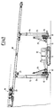
- FIGS. 1 and 2 illustrate a machine for the preventive consolidation of excavations in tunnels of the type described in patent application no. 67347-A/90 in the name of the same Inventor, which may be indicated for using the device according to the present invention.
- FIGS. 1 and 2 While a specific embodiment of the machine is illustrated in FIGS. 1 and 2, it is to be understood that such disclosure is merely for the purposes of illustration in that various modifications are possible without altering in any way the principles, aims and advantages of the invention itself.
- a frame 10 which forms the carrying structure of the machine is mounted on a motor driven tracked vehicle 11 and provided with pistons 12 having stabilising feet.
- a central power unit 13 is located on top of the frame 10 and it works the rotary working unit and the auxiliary units used for moving and positioning the machine.
- the working unit is single and it is formed by two telescopic standards 14 and 15 which are integral, at one extremity, with respective plates 16 and 17 and at the other extremity with a boom 18.
- Said boom is provided with a working unit 19, an engine 20 and a windlass 21 for moving the engine 2.
- the plates 16 and 17 that support the telescopic standards 14 and 15 are also provided with engines 22 wherein the pinions rotate on a toothed circumference 23 which is part of the plates.
- the plates are provided with a cursor that is able to slide along slides 24 that are vertical when the machine is working and are turned down in a horizontal position during transport.
- the slides 24 are pivotally connected to the frame 10 and pistons 25 worked by the power unit 13 for rotating horizontally the slides 24 and the standards 14 and 15 from which the boom 18 has to be previously removed.
- the device or loader according to the present invention is illustrated in its entirety in FIG. 2 with the reference 26, mounted on the machine by means of a support 2.
- the device or loader according to the present invention presents a number of rods 36, 37, 38.
- Each bar is housed in a tube 39 which isolates it from the bars on either side, the tube is in turn located inside a storage tube 3.
- the front extremity of the storage tube 34 ends in a funnel shape 35, the function of which is to direct the rods between the friction roller 32, which are rotated by a motor drive unit 33. In this way only one of the rods 36, 37, 38 stored in the loader is presented for use at a time.
- the tubes 39 should preferably be made of a material with a low friction coefficient which can slide easily.
- the tube 39 is an element with closed sides it protects the rods from dust and detritus.
- the feeding system for the rods is comprised of a thrusting means 44 at the end of which is fixed a plate 43 with fingers 40, 41 and 42 of different lengths, which make the rods 36, 37 and 38 advance in succession toward the pair of rollers 32. In this way the system can be used in any position in relation to the vertical.
- the distance between the rollers 32 can be regulated by means of a piston, which optimises the friction of the rollers on the rods.
- the bars should preferably be loaded by moving, for example by turning over or totally removing, the group of fingers 40, 41 and 42, in order to free rear access to the tube 39. It is thus possible to introduce the first rod 31 by hand making it advance until the rollers 32 can drag it.
- the rod 36 is then introduced and made to advance to a position further back, inside the funnel 35, and so on for the other rods 37 and 38, each being in positions still further back.
- the backward step between the rods is constant and corresponds to the difference in length of the fingers 40, 41 and 42 of the thrusting means 4
- thrusting means 44 as well as being a single device equipped with fingers 40, 41 and 42 can, being comprised only of the fingers separate from each other, consequently work one independently of the others.
- the loading operation is carried out with the personnel at the ground, that is with the perforation guide which carries the perforating equipment, and the loader, turned to its lowest position, thus ensuring that the work is carried out in conditions of the utmost safety.
Landscapes
- Engineering & Computer Science (AREA)
- Mining & Mineral Resources (AREA)
- Geology (AREA)
- Life Sciences & Earth Sciences (AREA)
- General Life Sciences & Earth Sciences (AREA)
- Geochemistry & Mineralogy (AREA)
- Structural Engineering (AREA)
- Environmental & Geological Engineering (AREA)
- Fluid Mechanics (AREA)
- Physics & Mathematics (AREA)
- Mechanical Engineering (AREA)
- Earth Drilling (AREA)
- Excavating Of Shafts Or Tunnels (AREA)
- Lining And Supports For Tunnels (AREA)
- Filling Or Discharging Of Gas Storage Vessels (AREA)
Applications Claiming Priority (2)
| Application Number | Priority Date | Filing Date | Title |
|---|---|---|---|
| ITTO980370 | 1998-04-30 | ||
| IT98TO000370A ITTO980370A1 (it) | 1998-04-30 | 1998-04-30 | Dispositivo di stivaggio e caricamento di barre di rinforzo del fronte e della volta di gallerie. |
Publications (3)
| Publication Number | Publication Date |
|---|---|
| EP0953725A2 true EP0953725A2 (fr) | 1999-11-03 |
| EP0953725A3 EP0953725A3 (fr) | 2003-01-22 |
| EP0953725B1 EP0953725B1 (fr) | 2004-06-09 |
Family
ID=11416724
Family Applications (1)
| Application Number | Title | Priority Date | Filing Date |
|---|---|---|---|
| EP99107628A Expired - Lifetime EP0953725B1 (fr) | 1998-04-30 | 1999-04-16 | Dispositif de stockage et chargement des tiges renforcées pour le front et la voûte d'un tunnel |
Country Status (5)
| Country | Link |
|---|---|
| EP (1) | EP0953725B1 (fr) |
| JP (1) | JP4397998B2 (fr) |
| AT (1) | ATE268862T1 (fr) |
| ES (1) | ES2222636T3 (fr) |
| IT (1) | ITTO980370A1 (fr) |
Cited By (2)
| Publication number | Priority date | Publication date | Assignee | Title |
|---|---|---|---|---|
| US10995563B2 (en) | 2017-01-18 | 2021-05-04 | Minex Crc Ltd | Rotary drill head for coiled tubing drilling apparatus |
| CN120739527A (zh) * | 2025-08-27 | 2025-10-03 | 中铁五局集团电务工程有限责任公司 | 一种隧道联络通道软弱围岩预处理装置 |
Families Citing this family (1)
| Publication number | Priority date | Publication date | Assignee | Title |
|---|---|---|---|---|
| KR100984742B1 (ko) | 2008-09-11 | 2010-10-01 | 현대로템 주식회사 | 대차 반송 시스템 |
Family Cites Families (7)
| Publication number | Priority date | Publication date | Assignee | Title |
|---|---|---|---|---|
| US3677345A (en) * | 1970-05-13 | 1972-07-18 | Otis Eng Corp | Pipe handling apparatus and method |
| IT1236446B (it) * | 1989-10-26 | 1993-03-09 | Dispositivo di caricamento armature | |
| IT1241223B (it) * | 1990-05-11 | 1993-12-29 | Trevi D.P.A. | Macchina per il consolidamento preventivo degli scavi di gallerie mediante la tecnica dell'ombrello protettivo |
| SE465092B (sv) * | 1990-07-10 | 1991-07-22 | Atlas Copco Constr & Mining | Anordning foer saettning av bergbult |
| AUPN571495A0 (en) * | 1995-09-28 | 1995-10-26 | Cram Australia Pty Ltd | Apparatus for the handling rods |
| AU716459B2 (en) * | 1995-09-28 | 2000-02-24 | Joy Mm Delaware, Inc. | Rod handling apparatus and method |
| US5720582A (en) * | 1996-06-27 | 1998-02-24 | Cannon Industries, Inc. | Bolt delivery system with linear bolt magazine |
-
1998
- 1998-04-30 IT IT98TO000370A patent/ITTO980370A1/it unknown
-
1999
- 1999-04-16 AT AT99107628T patent/ATE268862T1/de active
- 1999-04-16 ES ES99107628T patent/ES2222636T3/es not_active Expired - Lifetime
- 1999-04-16 EP EP99107628A patent/EP0953725B1/fr not_active Expired - Lifetime
- 1999-04-30 JP JP12505099A patent/JP4397998B2/ja not_active Expired - Fee Related
Cited By (3)
| Publication number | Priority date | Publication date | Assignee | Title |
|---|---|---|---|---|
| US10995563B2 (en) | 2017-01-18 | 2021-05-04 | Minex Crc Ltd | Rotary drill head for coiled tubing drilling apparatus |
| US11136837B2 (en) | 2017-01-18 | 2021-10-05 | Minex Crc Ltd | Mobile coiled tubing drilling apparatus |
| CN120739527A (zh) * | 2025-08-27 | 2025-10-03 | 中铁五局集团电务工程有限责任公司 | 一种隧道联络通道软弱围岩预处理装置 |
Also Published As
| Publication number | Publication date |
|---|---|
| JP2000002097A (ja) | 2000-01-07 |
| EP0953725B1 (fr) | 2004-06-09 |
| EP0953725A3 (fr) | 2003-01-22 |
| ITTO980370A1 (it) | 1999-10-30 |
| JP4397998B2 (ja) | 2010-01-13 |
| ES2222636T3 (es) | 2005-02-01 |
| ATE268862T1 (de) | 2004-06-15 |
Similar Documents
| Publication | Publication Date | Title |
|---|---|---|
| EP2924236B1 (fr) | Installation de forage minier | |
| CN213478364U (zh) | 一种锚杆转载机组 | |
| CN107083979A (zh) | 一种快速掘进后配套运输及支护系统 | |
| CN112943312A (zh) | 一种自动铺网装置及掘锚一体机 | |
| JP6426813B1 (ja) | トンネル工事におけるズリ搬送用連続ベルトコンベヤ装置のベルト延長作業方法 | |
| US3934363A (en) | Trench back filling and compacting apparatus | |
| EP0953725B1 (fr) | Dispositif de stockage et chargement des tiges renforcées pour le front et la voûte d'un tunnel | |
| DE102010031648B4 (de) | Beschickungsvorrichtung für Schüttgut | |
| IT8983495A1 (it) | Dispositivo di caricamento armature | |
| DE19757383A1 (de) | Universelles schweres Gerät | |
| CN214330664U (zh) | 煤矿工作面运输顺槽无反复运支系统 | |
| AU2004216593A1 (en) | Combination panline and utility drilling or bolting unit | |
| EP0424768A1 (fr) | Dispositif pour amener des boulons d'ancrage | |
| CN214577122U (zh) | 一种煤矿掘进支护装置 | |
| EP1127738A1 (fr) | Dispositif de chargement et de déchargement des véhicules | |
| CN212508065U (zh) | 一种具有分体式操作平台的掩护式锚杆台车 | |
| JPH10218332A (ja) | 可変傾斜ベルトコンベヤ装置 | |
| US3122250A (en) | Container handling apparatus | |
| DE3313435A1 (de) | Tunnelvortriebsmaschine | |
| JP4120743B2 (ja) | ロックボルトの収納取出ユニットおよび収納取出装置ならびに供給装置 | |
| CN217080551U (zh) | 一种巷道掘进用物料转运装置 | |
| CN217783503U (zh) | 一种可滑动反力支撑装置 | |
| CN217322885U (zh) | 一种现场混装乳化炸药车输药管收放装置 | |
| US3115258A (en) | Loading and transport of minerals in mines and quarries | |
| DE2423171A1 (de) | Schachtraeumgeraet |
Legal Events
| Date | Code | Title | Description |
|---|---|---|---|
| PUAI | Public reference made under article 153(3) epc to a published international application that has entered the european phase |
Free format text: ORIGINAL CODE: 0009012 |
|
| AK | Designated contracting states |
Kind code of ref document: A2 Designated state(s): AT BE CH CY DE DK ES FI FR GB GR IE IT LI LU MC NL PT SE |
|
| AX | Request for extension of the european patent |
Free format text: AL;LT;LV;MK;RO;SI |
|
| RAP1 | Party data changed (applicant data changed or rights of an application transferred) |
Owner name: TREVI S.P.A. |
|
| PUAL | Search report despatched |
Free format text: ORIGINAL CODE: 0009013 |
|
| RIC1 | Information provided on ipc code assigned before grant |
Free format text: 7E 21B 19/14 A, 7E 21D 20/00 B |
|
| AK | Designated contracting states |
Kind code of ref document: A3 Designated state(s): AT BE CH CY DE DK ES FI FR GB GR IE IT LI LU MC NL PT SE |
|
| AX | Request for extension of the european patent |
Free format text: AL;LT;LV;MK;RO;SI |
|
| 17P | Request for examination filed |
Effective date: 20030325 |
|
| GRAP | Despatch of communication of intention to grant a patent |
Free format text: ORIGINAL CODE: EPIDOSNIGR1 |
|
| AKX | Designation fees paid |
Designated state(s): AT CH ES FR IT LI |
|
| REG | Reference to a national code |
Ref country code: DE Ref legal event code: 8566 |
|
| GRAS | Grant fee paid |
Free format text: ORIGINAL CODE: EPIDOSNIGR3 |
|
| GRAA | (expected) grant |
Free format text: ORIGINAL CODE: 0009210 |
|
| AK | Designated contracting states |
Kind code of ref document: B1 Designated state(s): AT CH ES FR IT LI |
|
| REG | Reference to a national code |
Ref country code: CH Ref legal event code: EP |
|
| REG | Reference to a national code |
Ref country code: IE Ref legal event code: FG4D |
|
| REG | Reference to a national code |
Ref country code: CH Ref legal event code: NV Representative=s name: ROTTMANN, ZIMMERMANN + PARTNER AG |
|
| ET | Fr: translation filed | ||
| REG | Reference to a national code |
Ref country code: ES Ref legal event code: FG2A Ref document number: 2222636 Country of ref document: ES Kind code of ref document: T3 |
|
| PLBE | No opposition filed within time limit |
Free format text: ORIGINAL CODE: 0009261 |
|
| STAA | Information on the status of an ep patent application or granted ep patent |
Free format text: STATUS: NO OPPOSITION FILED WITHIN TIME LIMIT |
|
| 26N | No opposition filed |
Effective date: 20050310 |
|
| PG25 | Lapsed in a contracting state [announced via postgrant information from national office to epo] |
Ref country code: IT Free format text: LAPSE BECAUSE OF NON-PAYMENT OF DUE FEES Effective date: 20090416 |
|
| PGRI | Patent reinstated in contracting state [announced from national office to epo] |
Ref country code: IT Effective date: 20110616 |
|
| REG | Reference to a national code |
Ref country code: CH Ref legal event code: PFA Owner name: TREVI S.P.A. Free format text: TREVI S.P.A.#VIA DISMANO 5819#I-47023 CESENA (PROVINCE OF FORLI) (IT) -TRANSFER TO- TREVI S.P.A.#VIA DISMANO 5819#I-47023 CESENA (PROVINCE OF FORLI) (IT) |
|
| PGFP | Annual fee paid to national office [announced via postgrant information from national office to epo] |
Ref country code: IT Payment date: 20140423 Year of fee payment: 16 |
|
| REG | Reference to a national code |
Ref country code: FR Ref legal event code: PLFP Year of fee payment: 17 |
|
| PGFP | Annual fee paid to national office [announced via postgrant information from national office to epo] |
Ref country code: ES Payment date: 20150310 Year of fee payment: 17 |
|
| PGFP | Annual fee paid to national office [announced via postgrant information from national office to epo] |
Ref country code: CH Payment date: 20150414 Year of fee payment: 17 |
|
| PGFP | Annual fee paid to national office [announced via postgrant information from national office to epo] |
Ref country code: FR Payment date: 20150408 Year of fee payment: 17 Ref country code: AT Payment date: 20150325 Year of fee payment: 17 |
|
| PG25 | Lapsed in a contracting state [announced via postgrant information from national office to epo] |
Ref country code: IT Free format text: LAPSE BECAUSE OF NON-PAYMENT OF DUE FEES Effective date: 20150416 |
|
| REG | Reference to a national code |
Ref country code: DE Ref legal event code: R108 |
|
| REG | Reference to a national code |
Ref country code: CH Ref legal event code: PCAR Free format text: NEW ADDRESS: GARTENSTRASSE 28 A, 5400 BADEN (CH) |
|
| REG | Reference to a national code |
Ref country code: CH Ref legal event code: PL |
|
| REG | Reference to a national code |
Ref country code: AT Ref legal event code: MM01 Ref document number: 268862 Country of ref document: AT Kind code of ref document: T Effective date: 20160416 |
|
| REG | Reference to a national code |
Ref country code: FR Ref legal event code: ST Effective date: 20161230 |
|
| PG25 | Lapsed in a contracting state [announced via postgrant information from national office to epo] |
Ref country code: LI Free format text: LAPSE BECAUSE OF NON-PAYMENT OF DUE FEES Effective date: 20160430 Ref country code: FR Free format text: LAPSE BECAUSE OF NON-PAYMENT OF DUE FEES Effective date: 20160502 Ref country code: CH Free format text: LAPSE BECAUSE OF NON-PAYMENT OF DUE FEES Effective date: 20160430 |
|
| PG25 | Lapsed in a contracting state [announced via postgrant information from national office to epo] |
Ref country code: AT Free format text: LAPSE BECAUSE OF NON-PAYMENT OF DUE FEES Effective date: 20160416 |
|
| PG25 | Lapsed in a contracting state [announced via postgrant information from national office to epo] |
Ref country code: ES Free format text: LAPSE BECAUSE OF NON-PAYMENT OF DUE FEES Effective date: 20160417 |
|
| REG | Reference to a national code |
Ref country code: ES Ref legal event code: FD2A Effective date: 20181128 |