EP0424768A1 - Dispositif pour amener des boulons d'ancrage - Google Patents
Dispositif pour amener des boulons d'ancrage Download PDFInfo
- Publication number
- EP0424768A1 EP0424768A1 EP90119683A EP90119683A EP0424768A1 EP 0424768 A1 EP0424768 A1 EP 0424768A1 EP 90119683 A EP90119683 A EP 90119683A EP 90119683 A EP90119683 A EP 90119683A EP 0424768 A1 EP0424768 A1 EP 0424768A1
- Authority
- EP
- European Patent Office
- Prior art keywords
- reinforcement rods
- excavation equipment
- excavation
- reinforcement
- rods
- Prior art date
- Legal status (The legal status is an assumption and is not a legal conclusion. Google has not performed a legal analysis and makes no representation as to the accuracy of the status listed.)
- Withdrawn
Links
- 230000002787 reinforcement Effects 0.000 title claims abstract description 37
- 238000009412 basement excavation Methods 0.000 claims abstract description 47
- 238000005553 drilling Methods 0.000 description 15
- 239000004568 cement Substances 0.000 description 3
- 230000005540 biological transmission Effects 0.000 description 1
- 230000001419 dependent effect Effects 0.000 description 1
- 238000003780 insertion Methods 0.000 description 1
- 230000037431 insertion Effects 0.000 description 1
- 239000000463 material Substances 0.000 description 1
- 238000000034 method Methods 0.000 description 1
- 230000003014 reinforcing effect Effects 0.000 description 1
- 239000003381 stabilizer Substances 0.000 description 1
Images


Classifications
-
- E—FIXED CONSTRUCTIONS
- E21—EARTH OR ROCK DRILLING; MINING
- E21D—SHAFTS; TUNNELS; GALLERIES; LARGE UNDERGROUND CHAMBERS
- E21D5/00—Lining shafts; Linings therefor
-
- E—FIXED CONSTRUCTIONS
- E21—EARTH OR ROCK DRILLING; MINING
- E21D—SHAFTS; TUNNELS; GALLERIES; LARGE UNDERGROUND CHAMBERS
- E21D20/00—Setting anchoring-bolts
- E21D20/003—Machines for drilling anchor holes and setting anchor bolts
-
- E—FIXED CONSTRUCTIONS
- E21—EARTH OR ROCK DRILLING; MINING
- E21B—EARTH OR ROCK DRILLING; OBTAINING OIL, GAS, WATER, SOLUBLE OR MELTABLE MATERIALS OR A SLURRY OF MINERALS FROM WELLS
- E21B19/00—Handling rods, casings, tubes or the like outside the borehole, e.g. in the derrick; Apparatus for feeding the rods or cables
- E21B19/14—Racks, ramps, troughs or bins, for holding the lengths of rod singly or connected; Handling between storage place and borehole
Definitions
- This invention concerns a device to feed reinforcement rods.
- this invention concerns a device suitable to cooperate with an excavation equipment in providing that excavation equipment with non-recoverable reinforcement rods employed in the lengthwise reinforcing of tunnels.
- the device of the invention and the excavation equipment are normally borne on an excavation machine working at the excavation site.
- One of the systems used most often consists in making a series of lengthwise holes about the vault of the tunnel.
- each drilling step which is carried out with suitable tools on a shaft, the shaft is withdrawn from the hole drilled in the wall and a cement agglomerate is injected into the hole.
- the cycle is repeated at each hole drilled and therefore there is a continuous handling of the drilling shaft alternated from time to time with the feed of new rods to be inserted into the holes made in the wall.
- the drilling and the insertion of the reinforcement rods are normally carried out by the same excavation equipment, which is borne on an operating machine.
- the operating machine brings the excavation equipment, provided with the drilling shaft, from time to time to the hole to be drilled.
- the excavation equipment is normally moved to one of its two lower positions at the sides of the excavation machine, where the drilling shaft is removed and the reinforcement rod to be inserted is fitted by hand.
- the drilling equipment is then brought back to the hole previously made and filled with cement agglomerate in the meantime.
- the present applicant has as his objective a device able to overcome the problems of lifting and positioning the reinforcement rods on the excavation equipment.
- the device to feed reinforcement rods according to the invention is secured advantageously to a rear terminal portion of the excavation equipment at its part farthest from the excavation face.
- the device comprises means suitable to support and lift from the ground each reinforcement rod, including means to draw the rods so as to position them suitably on the excavation equipment.
- the device of the invention comprises also means to align and guide the rods while the latter are being positioned on the the excavation equipment.
- the device of the invention is suitable to cooperate advantageously with a reinforcement rod loader included on the excavation equipment and with an excavation machine, the loader and the machine being the subject of parallel patent applications in the name of the present applicant.
- a machine 10 to carry out lengthwise reinforcements in tunnels consists, in this example, of a tracked vehicle 37 equipped with a turret 11, which can be actuated to rotate continuously by 360° and is provided with stabilizers 12 for level positioning.
- a pair of structures 13 to support an excavation equipment 14 are hinged on the turret.
- the columns 17 bear at their ends the excavation equipment 14 and by means of the rotation thrust bearings 16 can travel through an angle "alpha" (see Fig. 2) in relation to the vertical so as to cover the whole field of drilling.
- the lowest positions A and B of the equipment 14 are those in which any work on the apparatus and drilling materials is carried out advantageously.
- the excavation equipment 14 consists of a support 18 for a drilling head 19 able to run along the support 18.
- the drilling head 19 is equipped in a known manner to actuate a drilling shaft 20 that cooperates with alignment guides 21 suitable to hold and align the shaft 20 on the drilling head 19.
- first vice 23 to clamp the drilling shaft 20 or reinforcement rod 25 and a second vice 24 for the unscrewing of the drilling shaft 20.
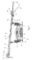
- a device 26 to feed reinforcement rods 25 according to the invention is included at the end of the excavation equipment 14 farthest from the excavation face 22 and is secured to the excavation equipment 14.
- the device 26 of the invention is suitable, when it is located with the excavation equipment 14 in position A or B of Fig. 2, to grip a reinforcement rod 25 placed beforehand on the ground behind the tracked vehicle 37.
- the device 26 then lifts the reinforcement rod 25 to the height of the excavation equipment 14 and thrusts it progressively forwards along the whole length of the excavation equipment 14 so as to position it suitably until the rod 25 is to be used.
- the device 26 cooperates advantageously with a means that loads the reinforcement rods 25 automatically.
- the device 26 to feed reinforcement rods 25 consists of a frame 28 connected to the excavation equipment 14 by a suitable structure 27.
- An arm 30 is hinged on the frame 28 at the pivot 29 and is suitable to support the rod 25 and to lift it from the ground; the arm 30 is actuated by a jack 31 so as to rotate by an angle "beta” (see Fig. 1).
- a lifting means 32 is also connected to the frame 28 and cooperates with the arm 30 by means of a cable or chain or rope 33 in lifting the reinforcement rod 25 from the ground and moving it towards the excavation equipment 14.
- the frame 28 comprises for this purpose a transmission roller 34 and a guide funnel 35 (see Fig. 4), both of which have the task of aligning and guiding the reinforcement rod 25.
- the cable 33 is passed through the funnel 35.
- the reinforcement rod 25 is then brought to a required position on the excavation equipment 14, for instance in correspondence with the drilling head 19, which can slide forward and position the reinforcement rod 25 in turn in correspondence with an automatic loader of reinforcement rods, as we said earlier.
- a thrust bearing 36 ensures the vertical positioning of the device 26, irrespective of the position of the excavation equipment 14 on the profile of the tunnel.
- the lifting means 32 is positioned at the excavation-face end of the excavation equipment 14.
Landscapes
- Engineering & Computer Science (AREA)
- Mining & Mineral Resources (AREA)
- Life Sciences & Earth Sciences (AREA)
- Geology (AREA)
- Geochemistry & Mineralogy (AREA)
- General Life Sciences & Earth Sciences (AREA)
- Mechanical Engineering (AREA)
- Environmental & Geological Engineering (AREA)
- Fluid Mechanics (AREA)
- Physics & Mathematics (AREA)
- Structural Engineering (AREA)
- Earth Drilling (AREA)
- Excavating Of Shafts Or Tunnels (AREA)
- Drilling And Exploitation, And Mining Machines And Methods (AREA)
- Generation Of Surge Voltage And Current (AREA)
- Charge And Discharge Circuits For Batteries Or The Like (AREA)
- Emergency Protection Circuit Devices (AREA)
Applications Claiming Priority (2)
| Application Number | Priority Date | Filing Date | Title |
|---|---|---|---|
| IT8349489 | 1989-10-26 | ||
| IT08349489A IT1236445B (it) | 1989-10-26 | 1989-10-26 | Dispositivo di alimentazione armature |
Publications (1)
| Publication Number | Publication Date |
|---|---|
| EP0424768A1 true EP0424768A1 (fr) | 1991-05-02 |
Family
ID=11322577
Family Applications (1)
| Application Number | Title | Priority Date | Filing Date |
|---|---|---|---|
| EP90119683A Withdrawn EP0424768A1 (fr) | 1989-10-26 | 1990-10-15 | Dispositif pour amener des boulons d'ancrage |
Country Status (5)
| Country | Link |
|---|---|
| US (1) | US5129764A (fr) |
| EP (1) | EP0424768A1 (fr) |
| JP (1) | JPH03158591A (fr) |
| KR (1) | KR910008251A (fr) |
| IT (1) | IT1236445B (fr) |
Cited By (3)
| Publication number | Priority date | Publication date | Assignee | Title |
|---|---|---|---|---|
| WO2001088325A1 (fr) * | 2000-05-17 | 2001-11-22 | Voest-Alpine Bergtechnik__Gesellschaft M.B.H. | Dispositif pour prolonger ou raccourcir des conduites |
| EP1167683A1 (fr) * | 2000-06-21 | 2002-01-02 | CASAGRANDE SpA | Ensemble d'introduction des barres d'armature pour les machines de forage |
| EP1167682A1 (fr) * | 2000-06-21 | 2002-01-02 | CASAGRANDE SpA | Machine à forer pour la préparation des excavations dans les tunnels |
Families Citing this family (4)
| Publication number | Priority date | Publication date | Assignee | Title |
|---|---|---|---|---|
| IT1257701B (it) * | 1991-10-25 | 1996-02-01 | Trevi Spa | Perfezionamenti al procedimento per l'esecuzione del rivestimento di una galleria ed apparecchiature atte allo scopo. |
| US6085852A (en) | 1995-02-22 | 2000-07-11 | The Charles Machine Works, Inc. | Pipe handling device |
| WO2003006786A1 (fr) * | 2001-07-12 | 2003-01-23 | Tracto-Technik Gmbh | Procede permettant de realiser des sondages |
| WO2012162617A2 (fr) * | 2011-05-26 | 2012-11-29 | Lavalley Industries, Llc | Fixation permettant de monter ou de démonter un tuyau |
Citations (2)
| Publication number | Priority date | Publication date | Assignee | Title |
|---|---|---|---|---|
| AT382428B (de) * | 1985-08-29 | 1987-02-25 | Vorspann Technik Gmbh | Gestaengemanipuliervorrichtung kombiniert mit bohrgeraet zum herstellen von bohrloechern |
| DE3610814A1 (de) * | 1986-04-01 | 1987-10-08 | Delmag Maschinenfabrik | Fahrbares bohr-, ramm- oder dergleichen geraet |
Family Cites Families (4)
| Publication number | Priority date | Publication date | Assignee | Title |
|---|---|---|---|---|
| DE382428C (de) * | 1921-07-15 | 1923-10-02 | Durand & Huguenin Ag | Verfahren zur Herstellung beizenfaerbender Farbstoffe der Triphenylmethanreihe |
| GB1493584A (en) * | 1974-11-19 | 1977-11-30 | Coal Ind | Mine equipment |
| US4264051A (en) * | 1978-01-17 | 1981-04-28 | Coal Industry (Patents) Limited | Laterally adjustable multiple head |
| GB8607997D0 (en) * | 1986-04-02 | 1986-05-08 | Boart Uk Ltd | Drilling boom |
-
1989
- 1989-10-26 IT IT08349489A patent/IT1236445B/it active IP Right Grant
-
1990
- 1990-10-10 US US07/595,363 patent/US5129764A/en not_active Expired - Fee Related
- 1990-10-15 EP EP90119683A patent/EP0424768A1/fr not_active Withdrawn
- 1990-10-17 KR KR1019900016530A patent/KR910008251A/ko not_active Withdrawn
- 1990-10-26 JP JP2290605A patent/JPH03158591A/ja active Pending
Patent Citations (2)
| Publication number | Priority date | Publication date | Assignee | Title |
|---|---|---|---|---|
| AT382428B (de) * | 1985-08-29 | 1987-02-25 | Vorspann Technik Gmbh | Gestaengemanipuliervorrichtung kombiniert mit bohrgeraet zum herstellen von bohrloechern |
| DE3610814A1 (de) * | 1986-04-01 | 1987-10-08 | Delmag Maschinenfabrik | Fahrbares bohr-, ramm- oder dergleichen geraet |
Cited By (3)
| Publication number | Priority date | Publication date | Assignee | Title |
|---|---|---|---|---|
| WO2001088325A1 (fr) * | 2000-05-17 | 2001-11-22 | Voest-Alpine Bergtechnik__Gesellschaft M.B.H. | Dispositif pour prolonger ou raccourcir des conduites |
| EP1167683A1 (fr) * | 2000-06-21 | 2002-01-02 | CASAGRANDE SpA | Ensemble d'introduction des barres d'armature pour les machines de forage |
| EP1167682A1 (fr) * | 2000-06-21 | 2002-01-02 | CASAGRANDE SpA | Machine à forer pour la préparation des excavations dans les tunnels |
Also Published As
| Publication number | Publication date |
|---|---|
| JPH03158591A (ja) | 1991-07-08 |
| IT1236445B (it) | 1993-03-09 |
| IT8983494A1 (it) | 1991-04-26 |
| KR910008251A (ko) | 1991-05-30 |
| US5129764A (en) | 1992-07-14 |
| IT8983494A0 (it) | 1989-10-26 |
Similar Documents
| Publication | Publication Date | Title |
|---|---|---|
| EP0424768A1 (fr) | Dispositif pour amener des boulons d'ancrage | |
| US5116164A (en) | Device to load reinforcement rods | |
| DE3919824C2 (de) | Drehbohreinrichtung | |
| US5695016A (en) | Auger telescoping hoist assembly and holding fork mechanism | |
| US3578809A (en) | Method and apparatus for forming subterranean structures | |
| WO2023025341A1 (fr) | Excavateur de puits | |
| JP3401704B2 (ja) | 吊込搬送装置 | |
| JPH06280476A (ja) | 多機能掘削機 | |
| DE102016015395B4 (de) | Vortriebsmaschine | |
| DE1608290A1 (de) | Vorrichtung zum Abteufen von Schaechten | |
| KR101940058B1 (ko) | 지반굴착교반장치 | |
| DE19625037C2 (de) | Erdbaugerät | |
| JPH1088993A (ja) | ロックボルト打設機 | |
| EP0473590B1 (fr) | Excavatrice mue par chenille et equipee d'un outil de travail separe | |
| DE3020570A1 (de) | Einrichtung und verfahren zur ermittlung von abweichungen bei der herstellung von bodenschlitzen | |
| DE2611181B2 (de) | Vorrichtung zum mechanischen Einbau von Streckenausbaurahmen | |
| EP0049925A2 (fr) | Excavateur hydraulique pour puits | |
| SU662716A1 (ru) | Устройство дл подводной разработки грунта | |
| DE4140755C1 (en) | Vertical shaft excavator for digging, loosening and/or loading - has holding bake with bracket with vertical main axis, round which swivels slewing arm | |
| EP1577253B1 (fr) | Treuil de halage | |
| CN113622939A (zh) | 一种隧道用运输装置及隧道掘进机 | |
| DE8709023U1 (de) | Drehbohrgerät zur Herstellung verrohrter Bohrlöcher | |
| DE102022210162A1 (de) | Hauptrahmen-drehmechanismus und drehverfahren für aushubvorrichtung | |
| JP2886089B2 (ja) | 軟弱地盤改良装置 | |
| WO2020172705A1 (fr) | Appareil d'exploitation minière |
Legal Events
| Date | Code | Title | Description |
|---|---|---|---|
| PUAI | Public reference made under article 153(3) epc to a published international application that has entered the european phase |
Free format text: ORIGINAL CODE: 0009012 |
|
| AK | Designated contracting states |
Kind code of ref document: A1 Designated state(s): AT BE CH DE DK ES FR GB GR LI LU NL SE |
|
| 17P | Request for examination filed |
Effective date: 19911007 |
|
| STAA | Information on the status of an ep patent application or granted ep patent |
Free format text: STATUS: THE APPLICATION HAS BEEN WITHDRAWN |
|
| 18W | Application withdrawn |
Withdrawal date: 19920312 |
|
| R18W | Application withdrawn (corrected) |
Effective date: 19920312 |