EP0953749B1 - Système d'alimentation en carburant des chambres de combustion des turbines à gaz avec compensation des pressions - Google Patents
Système d'alimentation en carburant des chambres de combustion des turbines à gaz avec compensation des pressions Download PDFInfo
- Publication number
- EP0953749B1 EP0953749B1 EP99303233A EP99303233A EP0953749B1 EP 0953749 B1 EP0953749 B1 EP 0953749B1 EP 99303233 A EP99303233 A EP 99303233A EP 99303233 A EP99303233 A EP 99303233A EP 0953749 B1 EP0953749 B1 EP 0953749B1
- Authority
- EP
- European Patent Office
- Prior art keywords
- fuel
- flow
- combustors
- pressure
- valve
- Prior art date
- Legal status (The legal status is an assumption and is not a legal conclusion. Google has not performed a legal analysis and makes no representation as to the accuracy of the status listed.)
- Expired - Lifetime
Links
- 239000000446 fuel Substances 0.000 title claims description 189
- 239000007788 liquid Substances 0.000 claims description 64
- 238000006073 displacement reaction Methods 0.000 claims description 21
- 239000000654 additive Substances 0.000 claims description 15
- 230000000996 additive effect Effects 0.000 claims description 9
- 238000005086 pumping Methods 0.000 claims description 9
- 238000012546 transfer Methods 0.000 claims description 6
- 238000000034 method Methods 0.000 claims description 3
- 238000011144 upstream manufacturing Methods 0.000 claims description 3
- 230000001276 controlling effect Effects 0.000 description 7
- 238000004519 manufacturing process Methods 0.000 description 5
- 238000002485 combustion reaction Methods 0.000 description 4
- 230000007423 decrease Effects 0.000 description 4
- 238000004891 communication Methods 0.000 description 2
- 238000013461 design Methods 0.000 description 2
- 239000002816 fuel additive Substances 0.000 description 2
- 230000001105 regulatory effect Effects 0.000 description 2
- 230000003247 decreasing effect Effects 0.000 description 1
- 230000001419 dependent effect Effects 0.000 description 1
- 238000009826 distribution Methods 0.000 description 1
- 230000009977 dual effect Effects 0.000 description 1
- 239000012530 fluid Substances 0.000 description 1
- 238000002347 injection Methods 0.000 description 1
- 239000007924 injection Substances 0.000 description 1
- 230000001050 lubricating effect Effects 0.000 description 1
- 239000010687 lubricating oil Substances 0.000 description 1
- 238000005461 lubrication Methods 0.000 description 1
- 238000012423 maintenance Methods 0.000 description 1
- 238000005259 measurement Methods 0.000 description 1
- 230000002028 premature Effects 0.000 description 1
- 230000000717 retained effect Effects 0.000 description 1
- 238000012552 review Methods 0.000 description 1
- 230000001360 synchronised effect Effects 0.000 description 1
- 230000007704 transition Effects 0.000 description 1
Images


Classifications
-
- F—MECHANICAL ENGINEERING; LIGHTING; HEATING; WEAPONS; BLASTING
- F02—COMBUSTION ENGINES; HOT-GAS OR COMBUSTION-PRODUCT ENGINE PLANTS
- F02C—GAS-TURBINE PLANTS; AIR INTAKES FOR JET-PROPULSION PLANTS; CONTROLLING FUEL SUPPLY IN AIR-BREATHING JET-PROPULSION PLANTS
- F02C9/00—Controlling gas-turbine plants; Controlling fuel supply in air- breathing jet-propulsion plants
- F02C9/26—Control of fuel supply
- F02C9/30—Control of fuel supply characterised by variable fuel pump output
-
- F—MECHANICAL ENGINEERING; LIGHTING; HEATING; WEAPONS; BLASTING
- F02—COMBUSTION ENGINES; HOT-GAS OR COMBUSTION-PRODUCT ENGINE PLANTS
- F02C—GAS-TURBINE PLANTS; AIR INTAKES FOR JET-PROPULSION PLANTS; CONTROLLING FUEL SUPPLY IN AIR-BREATHING JET-PROPULSION PLANTS
- F02C7/00—Features, components parts, details or accessories, not provided for in, or of interest apart form groups F02C1/00 - F02C6/00; Air intakes for jet-propulsion plants
- F02C7/22—Fuel supply systems
- F02C7/228—Dividing fuel between various burners
Definitions
- the present invention relates to a pressure compensated fuel delivery system for supplying liquid fuels to the combustors of a turbine and particularly relates to a liquid fuel delivery system for supplying low lubricity liquid fuels wherein lubricity additives and lubricity dosing equipment are eliminated.
- Heavy-duty gas turbines with can-annular combustion systems require a liquid fuel delivery system which can control total flow rate to and divide fuel flow accurately and equally among multiple combustion chambers.
- a can-annular combustion system consists of an arrangement of combustors about the turbine axis, each with a fuel injection system and a transition piece which provides a flow path for the hot gas from the combustor to the inlet of the turbine.
- Unequal fuel flow distribution to the combustion chambers can lead to temperature non-uniformity about the turbine which in turn can reduce turbine life.
- Heavy-duty gas turbine fuel delivery systems with can-annular combustors conventionally include, as major components, a positive displacement fuel pump, a bypass flow control valve, a mechanical flow divider and a controller.
- the positive displacement pump is driven by the turbine's accessory gear box or by an electric motor.
- the bypass control valve is positioned by the turbine controller to maintain the desired total liquid fuel flow rate for delivery to the flow divider.
- the mechanical flow divider uses a synchronized arrangement of paired gears to discharge the liquid fuel to the various combustors. Each pair of gears discharges fuel to a single combustor. The gears are identical and rotate at the same speed. Hence, the volumetric flow rate discharged to each combustor is nominally equal.
- a rotational speed feedback device i.e., magnetic pick-ups which sense rotation, is installed in the flow divider and provides a signal to the turbine controller proportional to the fuel flow rate.
- the controller uses the flow divider feedback signal in control algorithms to correctly position the bypass control valve, as well as to carry out other control functions.
- the flow divider also contains components which are in constant high speed rotary motion and are heavily loaded. Gears and bearings within the mechanical flow divider are lubricated by the liquid fuel itself. When low lubricity fuels are used, such fuels must be dosed with a fuel additive in order to avoid failure of the flow divider due to premature wear, galling, etc. However, these lubricity additives build up on the surfaces of the flow divider, causing it to bind up after a modest period of operation. The flow divider must then be removed from service, cleaned and overhauled. The additive also builds up on the internal surfaces of check valves downstream of the flow divider, causing them to leak or bind. The additive itself is costly and not always readily available in remote regions of the world.
- the problem addressed herein is to configure the fuel delivery system so as to control and divide fuel flow while accommodating a wide range of liquid fuel types, including fuels with poor lubricating properties and which system offers high reliability, low purchase and operating costs and low maintenance requirements. It is thus desirable to retrofit existing systems without replacement of the high pressure fuel pump, and also to offer original equipment systems which likewise eliminate the lubricity dosing problem and substitute a high reliability conventional centrifugal pump for the specially designed high pressure positive displacement fuel pump.
- a fuel delivery valve is known from the document US-A-4 027 699, however without means for pressure compensation during normal operation of the delivery valve.
- a fuel delivery system is provided particularly for use with low lubricity fuels and includes a pressure compensated fuel delivery valve (PCFD valve) comprising a multi-port fuel metering valve incorporating pressure compensation enabling the valve to deliver the same liquid fuel flow rate to each discharge port in communication with a combustor, notwithstanding line-to-line variations in delivery pressure.
- PCFD valve pressure compensated fuel delivery valve
- the valve thus performs the functions of flow control and flow division in a manner not requiring lubrication by the fuel.
- a flow meter is installed in the fuel line between the pump and the PCFD valve and provides a signal proportional to flow rate.
- a gas turbine controller responsive to that signal positions the PCFD valve actuator to control total fuel flow through the PCFD valve.
- the PCFD valve has a plurality of orifices on a valve actuator for controlling the flow rate through valve passages downstream of the orifices and which passages connect with the respective combustors.
- the PCFD valve splits the flow equally to each discharge passage. Because of the pressure compensation, variations in upstream and downstream pressure do not affect the equal volumetric flow rates delivered to the combustors.
- pump discharge pressure is measured by a pressure transducer installed at the pump discharge. While the volumetric output of the positive displacement pump is essentially constant, it is necessary for a percentage of the pump discharge flow to be recirculated back to the pump inlet via a bypass control valve.
- the bypass control valve is positioned by the turbine controller in accordance with a pump discharge pressure schedule. The pressure at the PCFD valve inlet is thus maintained at a level sufficient for proper flow control and division of fuel flow.
- the high pressure, positive displacement liquid fuel pump is replaced by a centrifugal pump.
- the high speed centrifugal pump is driven by an AC electric motor or by an accessory gear, the pump being a conventional design well suited to pumping low lubricity fluids.
- a flow meter as previously described is located between the centrifugal pump and the PCFD valve and the controller controls the PCFD valve to control the total fuel flow rate through the PCFD valve in response to measurements made by the flow meter. Thus, bypass control of the flow is unnecessary and is omitted.
- an existing fuel system such as a naphtha system, can retain its current positive displacement high pressure fuel pump, bypass control valve and other ancillary equipment, while effecting a replacement of the flow divider with the PCFD valve and flow control with the PCFD valve and flow meter.
- the high pressure positive displacement pump itself can be replaced using a reliable off-the-shelf substitute centrifugal pump, the flow meter and PCFD valve similarly providing flow control and division. This is particularly desirable for use with original equipment manufacture.
- a liquid fuel delivery system for a turbine comprising a plurality of combustors, a positive displacement pump for pumping liquid fuel to the combustors, a pressure compensated fuel delivery valve for receiving fuel from the pump and dividing,the fuel for flow to each of the combustors at an equal predetermined flow rate, a pressure transducer for determining the pressure of the liquid fuel downstream of the pump and upstream of the fuel delivery valve, a pressure control valve disposed between the pump and the fuel delivery valve, a flow meter for determining total rate of liquid fuel flow downstream of the pump and a controller coupled to the pressure transducer and the pressure control valve for controlling the pressure control valve to deliver fuel to the fuel delivery valve at a predetermined pressure and coupled to the flow meter and the delivery valve for controlling the total liquid fuel flow rate through the fuel delivery valve to the combustors.
- a method of supplying liquid fuel to the combustors of a turbine comprising the steps of supplying a low lubricity liquid fuel to a pump, pumping the low lubricity fuel through a main fuel supply line to the combustors, determining the pressure of the low lubricity liquid fuel in the main fuel supply line, controlling the pressure of the low lubricity liquid fuel in the main fuel supply line to a predetermined pressure in response to the step of determining the pressure, determining the rate of flow of the low lubricity liquid fuel in the main fuel supply line and controlling the total flow rate of the low lubricity liquid fuel through the delivery valve to the combustors in response to the step of determining the rate of flow and dividing the total flow of the low lubricity liquid fuel to provide equal rates of flow of the fuel to the combustors.
- a liquid fuel delivery system for a turbine comprising a plurality of combustors, a centrifugal pump for pumping liquid fuel to the combustors, a pressure compensated fuel delivery valve for receiving fuel from the pump and dividing and delivering fuel at a predetermined flow rate to each of the combustors, a flow meter for measuring the rate of total liquid fuel flow to the pressure compensated fuel delivery valve, a controller coupled to the flow meter and the fuel delivery valve for controlling the total liquid fuel flow rate through the pressure compensated fuel delivery valve to the combustors.
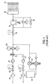
- FIG. 1 there is illustrated a liquid fuel delivery system according to the prior art for delivering liquid fuel to a typical heavy-duty gas turbine with can-annular combustors, for example, the combustors schematically illustrated at 10.
- Fuel is delivered from a source by forwarding pumps, not shown, which deliver, for example, two liquid fuels, naphtha and a distillate, to the fuel system.
- a distillate is supplied to the combustors at turbine start-up and shut-down, while naphtha is supplied during operating conditions.
- the distillate is supplied through a filter 12, a pressure regulating valve 14, a flow meter 16 and a fuel transfer valve 18.
- Naphtha may be provided through a filter 20, a pressure regulating valve 22, and a flow meter 24 to the fuel transfer valve 18. It will be appreciated that other types of liquid fuels may be employed and that the invention is not limited to a combination of naphtha and distillate or any one of those fuels.
- the fuel transfer valve supplies one or the other of the liquid fuels to the combustors of the turbine.
- the fuel supplied to the fuel transfer valve 18 is then passed through duplex filters 26 and on to a shut-off valve 28.
- a lubricity additive is provided the fuel.
- a source 30 of lubricity additive is provided and dual metering pumps 32 supply the additive to the fuel line downstream of the duplex filters 26 and prior to a stop valve 28.
- a positive displacement pump 34 e.g., a screw pump, supplies the liquid fuel at high pressure to a flow divider 36.
- the flow divider 36 employs sets of paired gears to discharge fuel to respective combustors, the gears for all combustors rotating at the same speed, hence providing a nominally equal volumetric flow rate to each combustor.
- a rotational speed feedback device not shown, to provide a signal to the turbine controller proportional to fuel flow rate.
- the controller uses this signal to control a bypass control valve 38 to control the flow rate provided the divider by the positive displacement pump 34.
- the gears and bearings of the flow divider must be lubricated when low or non-existent lubricious fuels are supplied. Those fuel additives build up on the surfaces of the flow divider, disadvantageously requiring it to be serviced periodically.
- FIG 2 there is illustrated a liquid fuel delivery system according to the present invention wherein like reference numerals are applied to like parts as in the prior art of Figure 1 followed by the suffix "a.”
- the two liquid fuels are provided to the fuel transfer valve 18a similarly as described in the prior art of Figure 1.
- the lubricity additive tank 30 the metering pumps 32 and supply lines for supplying a lubricity additive to the fuel.
- the present fuel delivery system has no need for lubricity additives or ancillary equipment necessary to supply the additives.
- the pressure of the liquid fuel supplied by the positive displacement pump 34a is controlled to a predetermined pressure
- the flow rate to the combustors is controlled by the PCFD valve in combination with the controller and a flow meter, and the flow division is accomplished by the PCFD valve.
- the positive displacement pump 34a provides liquid fuel at a volumetric flow rate at a normally higher pressure than needed by the PCFD valve.
- a pressure transducer 39 monitors the pressure of the liquid fuel in the main supply line 40 and provides an output signal to controller 42.
- the controller supplies a signal to the bypass pressure control valve 38a.
- the control valve 38a is identical in structure to the bypass control valve 38 of the system illustrated in Figure 1. However, the valve 38a controls pressure in the supply line 40 and not flow rate. Hence, by sensing the pressure in line 40, the controller adjusts the bypass pressure control valve 38a to supply liquid fuel in line 40 at a predetermined pressure.
- a flow meter 41 is also positioned in line 40 and provides a signal proportional to the flow rate in line 40 to the controller 42.
- the controller 42 controls an actuator for the PCFD valve.
- the position of the actuator of the PCFD valve determines the flow rate through each of the outlet passages of the valve and which passages are coupled to the combustors whereby exactly equal flow rates are provided each combustor.
- the PCFD valve affords pressure compensation so that the pressure differential across each of the orifices through the PCFD valve is the same, thus ensuring a constant flow rate through each outlet passage.
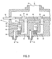
- the fuel delivery valve 44 includes a valve housing 46 having a fuel inlet 48 coupled to the fuel line 40 for receiving fuel into a plenum 50 at a predetermined pressure.
- the valve body 46 includes passages 52 corresponding in number to the number of combustors 10, each passage 52 supplying an individual combustor with fuel from inlet 48.
- An actuator 54 having a plurality of orifices 56 is disposed in the valve body 46. From a review of Figure 3, it will be appreciated that the linear motion of the actuator 54 registers to a greater or lesser extent orifices 56 with respective passages 52 to supply more or less fuel, dependent upon the position of the actuator 54.
- valved apertures 53 defined between the orifices 56 and passages 52.
- pressure compensating spring-biased spool valve 60 Downstream of each orifice 56, there is also provided a pressure compensating spring-biased spool valve 60.
- Each spool valve 60 lies in a chamber 62 in communication via passageway 64 with the liquid fuel at constant pressure in the plenum 50.
- the passageways 64 are connected to one another via a manifold 66. Consequently, the upper surfaces of the pistons 60 are exposed to the pressure of the liquid fuel supplied to the PCFD valve.
- the opposite side of each piston 60 communicates with the associated passageway 52.
- a valved aperture 68 is located at each juncture of the lower end of the piston 60 and a fuel discharge line 70 to a combustor 10.
- this structure compensates for changes in system pressure and provides identical flow rates to each combustor. For example, if the downstream pressure in any fuel discharge line 70 to a combustor increases, then the increase in downstream pressure will cause the corresponding compensator spool valve 60 to incrementally open the aperture 68 to reduce the pressure drop across the valve by exactly the same amount as the increase in downstream pressure. Consequently, a constant flow rate is maintained as downstream pressure increases. Conversely, in the event of a decrease in downstream pressure, the compensator spool valve 60 incrementally closes the aperture 68, increasing the pressure drop across the line by exactly the same amount as the decrease in fuel nozzle pressure drop. Again, an identical flow rate is ensured to each combustor.
- the controller 42 in response to the signal to the controller from the flow meter, the controller 42 through various algorithms operates the actuator 54 of the PCFD valve 44 to provide a selected identical flow rate through the valved apertures 53 depending upon the operating condition of the turbine.
- the pressure transducer also inputs a signal to the controller 42 which, in turn, controls the bypass pressure control valve 38a to dump excess flow from line 40 thereby providing a predetermined liquid fuel pressure in line 40 and in the PCFD valve.
- the present invention controls the pressure in the fuel supply line 40 by using the pressure transducer 39 and controller 42 to control the bypass pressure control valve 38a.
- the controller 42 in response to a signal from the flow meter 41, operates PCFD valve 44 to provide a constant liquid fuel flow rate and division in equal parts of the fuel flow to the combustors through the discharge outlets 70.
- FIG 4 there is illustrated a further embodiment of the present invention, particularly useful for original equipment manufacture, wherein like reference numerals are applied to like parts, followed by the suffix "b.”
- the positive displacement pump 34 is replaced by a conventional centrifugal pump 70.
- the centrifugal pump 70 does not require a bypass control valve because the centrifugal pump readily adapts to different flow rates.
- a flow meter 72 is provided in the supply line between the centrifugal pump 70 and the PCFD valve 44b and provides a signal to the controller 42b.
- the controller 42b uses that signal to displace the actuator 54 of the PCFD valve 44b to afford flow control and equal division of the flow to the various combustors.
- the controller senses the increased load and simultaneously opens the valved apertures 53 of the PCFD valve to provide additional fuel to the combustors. Conversely, as the load decreases, the controller senses the decreased load and simultaneously decreases the valved apertures 53 through the PCFD valve to reduce the fuel flow, while continuing to provide pressure compensated equal flow to each combustor.
- variable frequency inverter drive may be provided the pump's AC motor.
- the variable frequency drive reduces the speed of the AC motor driven pump at part load conditions. Using this type of motor drive improves system energy efficiency at part load conditions by allowing the pump to run at a reduced speed, thereby reducing power consumption and eliminating the need for a pump recirculation flow. Also, the accuracy of the flow division and flow rate control at low loads is improved by reducing the pressure drop across the flow compensating elements in the PCFD valve.
Landscapes
- Engineering & Computer Science (AREA)
- Chemical & Material Sciences (AREA)
- Combustion & Propulsion (AREA)
- Mechanical Engineering (AREA)
- General Engineering & Computer Science (AREA)
- Feeding And Controlling Fuel (AREA)
Claims (5)
- Système d'alimentation en combustible liquide pour turbine, comprenant :une pluralité de dispositifs de combustion (10) ;une pompe à déplacement positif (34a) pour pomper du combustible liquide jusqu'aux dispositifs de combustion (10) ;une vanne d'alimentation en combustible compensée en pression (44) destinée à recevoir du combustible de ladite pompe (34a) et à diviser le combustible pour l'envoyer à chacun desdits dispositifs de combustion (10) au même débit prédéterminé ;un transducteur de pression (39) pour déterminer la pression du combustible liquide en aval de ladite pompe (34a) et en amont de ladite vanne d'alimentation en combustible (44) ;une vanne de régulation de pression (38a) disposée entre ladite pompe (34a) et ladite vanne d'alimentation en combustible (44) ;un débitmètre (41) pour déterminer le débit total du combustible liquide en aval de ladite pompe (34a) ; etun contrôleur (42) couplé audit transducteur de pression (39) et à ladite vanne de régulation de pression (38a) pour commander la vanne de régulation de pression (38a) pour envoyer du combustible à ladite vanne d'alimentation en combustible (44) à une pression prédéterminée et couplé audit débitmètre (41) et à ladite vanne d'alimentation (44) pour commander le débit total de combustible liquide dans ladite vanne d'alimentation en combustible (44) transmis auxdits dispositifs de combustion (10).
- Système d'alimentation selon la revendication 1, comprenant une ligne principale d'alimentation en combustible, une première ligne d'alimentation en combustible pour fournir un combustible liquide à faible onctuosité à ladite ligne principale d'alimentation en combustible, une deuxième ligne d'alimentation en combustible pour fournir un distillat à ladite ligne principale d'alimentation en combustible, une vanne de transfert (18a) de combustible pour transférer du combustible d'une ligne choisie parmi lesdites première et deuxième lignes d'alimentation à ladite pompe (34a) via ladite ligne principale d'alimentation en combustible, ladite ligne principale d'alimentation en combustible fournissant du combustible de ladite première ligne d'alimentation en combustible sans additif d'onctuosité envoyé soit dans ladite première ligne d'alimentation soit dans ladite ligne principale d'alimentation.
- Procédé pour fournir du combustible liquide aux dispositifs de combustion d'une turbine, comprenant les étapes consistant à :fournir un combustible liquide à faible onctuosité à une pompe ;pomper le combustible à faible onctuosité jusqu'auxdits dispositifs de combustion via une ligne principale d'alimentation en combustible ;déterminer la pression du combustible liquide à faible onctuosité dans la ligne principale d'alimentation en combustible ;réguler la pression du combustible liquide à faible onctuosité dans la ligne principale d'alimentation en combustible à une pression prédéterminée, en réponse à l'étape de détermination de la pression ;déterminer le débit du combustible liquide à faible onctuosité dans la ligne principale d'alimentation en combustible ; etréguler le débit total du combustible liquide à faible onctuosité aux dispositifs de combustion à travers ladite vanne d'alimentation en réponse à l'étape de détermination du débit ; etdiviser l'écoulement total du combustible liquide à faible onctuosité pour fournir des débits identiques du combustible auxdits dispositifs de combustion.
- Procédé selon la revendication 3, dans lequel l'étape de pompage comprend le fait de pomper du combustible au moyen d'une pompe à déplacement positif.
- Système d'alimentation en combustible liquide pour turbine, comprenant :une pluralité de dispositifs de combustion ;une pompe centrifuge pour pomper du combustible liquide jusqu'aux dispositifs de combustion ;une vanne d'alimentation en combustible compensée en pression destinée à recevoir du combustible de ladite pompe et à diviser et envoyer le combustible à un débit prédéterminé à chacun desdits dispositifs de combustion ;un débitmètre pour mesurer le débit total du combustible liquide envoyé à ladite vanne d'alimentation en combustible compensée en pression ;un contrôleur couplé audit débitmètre et à ladite vanne d'alimentation en combustible pour commander le débit total de combustible liquide dans ladite vanne d'alimentation en combustible compensée en pression transmis auxdits dispositifs de combustion.
Applications Claiming Priority (2)
| Application Number | Priority Date | Filing Date | Title |
|---|---|---|---|
| US09/069,409 US6079198A (en) | 1998-04-29 | 1998-04-29 | Pressure compensated fuel delivery system for the combustors of turbomachinery |
| US69409 | 1998-04-29 |
Publications (3)
| Publication Number | Publication Date |
|---|---|
| EP0953749A2 EP0953749A2 (fr) | 1999-11-03 |
| EP0953749A3 EP0953749A3 (fr) | 2002-01-09 |
| EP0953749B1 true EP0953749B1 (fr) | 2005-08-24 |
Family
ID=22088796
Family Applications (1)
| Application Number | Title | Priority Date | Filing Date |
|---|---|---|---|
| EP99303233A Expired - Lifetime EP0953749B1 (fr) | 1998-04-29 | 1999-04-27 | Système d'alimentation en carburant des chambres de combustion des turbines à gaz avec compensation des pressions |
Country Status (6)
| Country | Link |
|---|---|
| US (1) | US6079198A (fr) |
| EP (1) | EP0953749B1 (fr) |
| JP (1) | JPH11324719A (fr) |
| KR (1) | KR100391535B1 (fr) |
| DE (1) | DE69926831T2 (fr) |
| TW (1) | TW387048B (fr) |
Families Citing this family (33)
| Publication number | Priority date | Publication date | Assignee | Title |
|---|---|---|---|---|
| EP1199453A3 (fr) * | 1998-05-08 | 2003-01-22 | Mitsubishi Heavy Industries, Ltd. | Système de lavage des injecteurs de carburant d'une turbine à gaz |
| US6385960B1 (en) * | 1999-10-14 | 2002-05-14 | General Electric Company | Methods and apparatus for operation of gas turbines |
| US6655151B2 (en) | 2001-09-07 | 2003-12-02 | Honeywell International, Inc. | Method for controlling fuel flow to a gas turbine engine |
| JP3978086B2 (ja) * | 2002-05-31 | 2007-09-19 | 三菱重工業株式会社 | 航空機用ガスタービンシステム,及びガスタービンシステム並びにその動作方法 |
| US7640723B2 (en) * | 2005-12-16 | 2010-01-05 | Hamilton Sundstrand Corporation | Engine with fuel/lubricant supply system for bearing lubrication |
| US7841184B2 (en) | 2007-04-19 | 2010-11-30 | Pratt & Whitney Canada Corp. | Start flow measurement |
| US8127548B2 (en) * | 2008-02-21 | 2012-03-06 | Honeywell International Inc. | Hybrid electrical/mechanical turbine engine fuel supply system |
| US8172512B2 (en) * | 2008-04-23 | 2012-05-08 | Hamilton Sundstrand Corporation | Accessory gearbox system with compressor driven seal air supply |
| US8234870B2 (en) * | 2009-04-17 | 2012-08-07 | Hamilton Sundstrand Corporation | Additive injection system for improving thermal stability of jet fuel |
| FR2945075B1 (fr) * | 2009-04-29 | 2015-06-05 | Snecma | Procede et dispositif pour alimenter une chambre de turbomachine avec un debit de carburant regule |
| US20120092950A1 (en) * | 2010-10-15 | 2012-04-19 | Bertrand Michel Jean-Claude Colomb | Low pressure drop blender |
| FR2973828B1 (fr) * | 2011-04-11 | 2014-04-18 | Snf Sas | Ensemble de materiel de mesure et regulation de viscosite en ligne a haute pression |
| CN102678336A (zh) * | 2011-12-06 | 2012-09-19 | 中国船舶重工集团公司第七�三研究所 | 一种天然气燃料燃气轮机机带燃料系统 |
| US9353688B2 (en) | 2013-01-17 | 2016-05-31 | Honeywell International Inc. | High pressure, multiple metering zone gas turbine engine fuel supply system |
| GB201313142D0 (en) | 2013-07-23 | 2013-09-04 | Rolls Royce Engine Control Systems Ltd | Engine Fuel Control System |
| US9758458B2 (en) * | 2013-08-20 | 2017-09-12 | Lg Chem, Ltd. | Method for purifying isopropyl alcohol |
| JP6300050B2 (ja) * | 2013-08-20 | 2018-03-28 | エルジー・ケム・リミテッド | イソプロピルアルコールの精製方法 |
| US10294866B2 (en) * | 2013-11-20 | 2019-05-21 | Woodward, Inc. | Parallel metering pressure regulation system with integrated flow meter placement |
| EP2889467B1 (fr) | 2013-12-30 | 2016-09-28 | Rolls-Royce Corporation | Diviseur de débit de carburant et système de surveillance de la santé d'un système de carburant d'une turbine à gaz |
| US20160178204A1 (en) * | 2014-12-18 | 2016-06-23 | Rolls-Royce Plc | Means and arrangement for fuel icing protection |
| EP3043228B1 (fr) | 2015-01-09 | 2018-09-19 | Levitronix GmbH | Régulateur d'écoulement et procédé de réglage d'un débit volumique prédéfini |
| US11022041B2 (en) * | 2015-10-13 | 2021-06-01 | Raytheon Technologies Corporation | Sensor snubber block for a gas turbine engine |
| US20170107908A1 (en) * | 2015-10-15 | 2017-04-20 | General Electric Company | Controlling Injection of Bio-Diesel into a Gas Turbine Combustor |
| US10337412B2 (en) * | 2016-06-16 | 2019-07-02 | General Electric Company | Liquid fuel control valve for gas turbine engine and method for controlling flow of liquid fuel to engine |
| US10428816B2 (en) | 2016-10-24 | 2019-10-01 | Hamilton Sundstrand Corporation | Variable speed multi-stage pump |
| US10844788B2 (en) * | 2017-06-19 | 2020-11-24 | General Electric Company | Fuel additive injection system and methods for inhibiting coke formation |
| FR3096412B1 (fr) * | 2019-05-24 | 2022-07-22 | Safran Aircraft Engines | Systeme d’alimentation en carburant d’une turbomachine avec regulation du debit de carburant |
| PL431661A1 (pl) * | 2019-10-30 | 2021-05-04 | General Electric Company | Układ i sposób działania komory spalania z wieloma paliwami ciekłymi |
| US11913380B2 (en) | 2020-01-07 | 2024-02-27 | Yantai Jereh Petroleum Equipment & Technologies Co., Ltd. | Gas source system for supplying combustion gas to a turbine engine by fracturing manifold equipment |
| CN111089003B (zh) | 2020-01-07 | 2024-12-17 | 烟台杰瑞石油装备技术有限公司 | 一种利用压裂管汇设备给涡轮发动机供气的气源系统 |
| US11713718B2 (en) | 2021-09-30 | 2023-08-01 | Hamilton Sundstrand Corporation | Dual valve fluid metering system |
| WO2023082481A1 (fr) * | 2021-11-09 | 2023-05-19 | 烟台杰瑞石油装备技术有限公司 | Système et procédé d'alimentation en gaz de combustion, dispositif équipé d'un moteur à turbine et système de fracturation |
| DE102022211312A1 (de) | 2022-10-25 | 2024-04-25 | Rolls-Royce Deutschland Ltd & Co Kg | Ventilbaugruppe, Kraftstoffsystem und Verfahren zum Betreiben einer Ventilbaugruppe |
Family Cites Families (11)
| Publication number | Priority date | Publication date | Assignee | Title |
|---|---|---|---|---|
| US2986335A (en) * | 1960-01-28 | 1961-05-30 | Ralph O Turnquist | Turbojet engine fuel distribution system |
| SE390332B (sv) * | 1974-10-02 | 1976-12-13 | Stal Laval Turbin Ab | Manoverventil for att forbinda ett antal forbrukningsstellen med ett gemensamt tillopp |
| GB2106017B (en) * | 1981-09-10 | 1985-10-30 | Ex Cell O Corp | Fuel distribution valve |
| GB2125110A (en) * | 1982-08-11 | 1984-02-29 | United Technologies Corp | Gas turbine augmentor fuel control system |
| JPS61241425A (ja) * | 1985-04-17 | 1986-10-27 | Hitachi Ltd | ガスタ−ビンの燃料ガス制御方法及び制御装置 |
| US4608820A (en) * | 1985-05-03 | 1986-09-02 | Chandler Evans Inc. | Dual stepper motor actuator for fuel metering valve |
| GB8517744D0 (en) * | 1985-07-12 | 1995-11-08 | Rolls Royce | Fuel control system |
| GB2197909B (en) * | 1986-11-26 | 1991-07-31 | Rolls Royce Plc | Fuel control system for gas turbine aeroengine overspeed protection. |
| GB9022387D0 (en) * | 1990-10-16 | 1990-11-28 | Lucas Ind Plc | Fuel control system for a gas turbine engine |
| US5259186A (en) * | 1991-03-08 | 1993-11-09 | General Electric Company | Gas turbine fuel control |
| FR2710688B1 (fr) * | 1993-09-29 | 1995-11-03 | Snecma | Dispositif de répartition du carburant entre plusieurs injecteurs. |
-
1998
- 1998-04-29 US US09/069,409 patent/US6079198A/en not_active Expired - Lifetime
-
1999
- 1999-04-16 TW TW088106148A patent/TW387048B/zh not_active IP Right Cessation
- 1999-04-26 KR KR10-1999-0014837A patent/KR100391535B1/ko not_active Expired - Fee Related
- 1999-04-27 DE DE69926831T patent/DE69926831T2/de not_active Expired - Fee Related
- 1999-04-27 JP JP11118949A patent/JPH11324719A/ja active Pending
- 1999-04-27 EP EP99303233A patent/EP0953749B1/fr not_active Expired - Lifetime
Also Published As
| Publication number | Publication date |
|---|---|
| KR100391535B1 (ko) | 2003-07-12 |
| JPH11324719A (ja) | 1999-11-26 |
| TW387048B (en) | 2000-04-11 |
| EP0953749A3 (fr) | 2002-01-09 |
| DE69926831T2 (de) | 2006-06-22 |
| EP0953749A2 (fr) | 1999-11-03 |
| KR19990083474A (ko) | 1999-11-25 |
| DE69926831D1 (de) | 2005-09-29 |
| US6079198A (en) | 2000-06-27 |
Similar Documents
| Publication | Publication Date | Title |
|---|---|---|
| EP0953749B1 (fr) | Système d'alimentation en carburant des chambres de combustion des turbines à gaz avec compensation des pressions | |
| CA2492914C (fr) | Systeme ameliore de fourniture de carburant | |
| CN1051358C (zh) | 润滑油泵及调节其泵送流量的方法 | |
| US6058694A (en) | Gas turbine engine commanded oil flow valve with failsafe | |
| US7509793B2 (en) | Fluid system | |
| US5067454A (en) | Self compensating flow control lubrication system | |
| KR100287814B1 (ko) | 압축기 윤활 시스템을 조절하기 위한 방법 및 장치 | |
| US9133772B2 (en) | Fuel system | |
| US11629652B2 (en) | Metering pump system | |
| US20140205472A1 (en) | Dual pump/dual bypass fuel pumping system | |
| CN114051555A (zh) | 确定用于在飞行器发动机的燃料供给回路中计量燃料的燃料密度的方法 | |
| US4899535A (en) | Turbojet fuel supply system with fuel recycling | |
| EP1344917B1 (fr) | Système de régulation d'alimentation en carburant | |
| US2936028A (en) | Multi-nozzle gas turbine fuel system with positive metering devices | |
| CN115380157A (zh) | 燃料消耗测量系统 | |
| US3614269A (en) | Integrated pump-control system using a unitized pump | |
| JPH0222220B2 (fr) | ||
| US20050072160A1 (en) | Method and system for fuel control in a gas turbine engine | |
| US12618410B2 (en) | Fuel system with electric generator integrated boost stage | |
| US12524027B2 (en) | Fuel system with boosted and cooled variable displacement main fuel pump and electromechanical actuators | |
| CN223854815U (zh) | 一种齿轮箱用开放式供油系统 | |
| CN121511357A (zh) | 用于对无油压缩式压缩机进行供给的油路和用于为这种压缩机供油而调节油参数的方法 | |
| CN121402360A (zh) | 一种齿轮箱润滑冲洗系统 | |
| CN120159672A (zh) | 一种用于高压共轨电控柴油机的供油泵油路系统 | |
| EP0118770A1 (fr) | Méthode et installation de distribution d'un certain débit de combustible liquide à une pluralité de postes de consommation dans des foyers industriels |
Legal Events
| Date | Code | Title | Description |
|---|---|---|---|
| PUAI | Public reference made under article 153(3) epc to a published international application that has entered the european phase |
Free format text: ORIGINAL CODE: 0009012 |
|
| AK | Designated contracting states |
Kind code of ref document: A2 Designated state(s): AT BE CH CY DE DK ES FI FR GB GR IE IT LI LU MC NL PT SE Kind code of ref document: A2 Designated state(s): CH DE FR GB IT LI |
|
| AX | Request for extension of the european patent |
Free format text: AL;LT;LV;MK;RO;SI |
|
| PUAL | Search report despatched |
Free format text: ORIGINAL CODE: 0009013 |
|
| AK | Designated contracting states |
Kind code of ref document: A3 Designated state(s): AT BE CH CY DE DK ES FI FR GB GR IE IT LI LU MC NL PT SE |
|
| AX | Request for extension of the european patent |
Free format text: AL;LT;LV;MK;RO;SI |
|
| 17P | Request for examination filed |
Effective date: 20020709 |
|
| AKX | Designation fees paid |
Free format text: CH DE FR GB IT LI |
|
| GRAP | Despatch of communication of intention to grant a patent |
Free format text: ORIGINAL CODE: EPIDOSNIGR1 |
|
| GRAS | Grant fee paid |
Free format text: ORIGINAL CODE: EPIDOSNIGR3 |
|
| GRAA | (expected) grant |
Free format text: ORIGINAL CODE: 0009210 |
|
| AK | Designated contracting states |
Kind code of ref document: B1 Designated state(s): CH DE FR GB IT LI |
|
| REG | Reference to a national code |
Ref country code: GB Ref legal event code: FG4D |
|
| REG | Reference to a national code |
Ref country code: CH Ref legal event code: NV Representative=s name: SERVOPATENT GMBH Ref country code: CH Ref legal event code: EP |
|
| REF | Corresponds to: |
Ref document number: 69926831 Country of ref document: DE Date of ref document: 20050929 Kind code of ref document: P |
|
| ET | Fr: translation filed | ||
| PLBE | No opposition filed within time limit |
Free format text: ORIGINAL CODE: 0009261 |
|
| STAA | Information on the status of an ep patent application or granted ep patent |
Free format text: STATUS: NO OPPOSITION FILED WITHIN TIME LIMIT |
|
| 26N | No opposition filed |
Effective date: 20060526 |
|
| REG | Reference to a national code |
Ref country code: CH Ref legal event code: PFA Owner name: GENERAL ELECTRIC COMPANY Free format text: GENERAL ELECTRIC COMPANY#1 RIVER ROAD#SCHENECTADY, NY 12345 (US) -TRANSFER TO- GENERAL ELECTRIC COMPANY#1 RIVER ROAD#SCHENECTADY, NY 12345 (US) |
|
| PGFP | Annual fee paid to national office [announced via postgrant information from national office to epo] |
Ref country code: DE Payment date: 20080602 Year of fee payment: 10 Ref country code: CH Payment date: 20080430 Year of fee payment: 10 |
|
| PGFP | Annual fee paid to national office [announced via postgrant information from national office to epo] |
Ref country code: IT Payment date: 20080428 Year of fee payment: 10 |
|
| PGFP | Annual fee paid to national office [announced via postgrant information from national office to epo] |
Ref country code: FR Payment date: 20080417 Year of fee payment: 10 |
|
| PGFP | Annual fee paid to national office [announced via postgrant information from national office to epo] |
Ref country code: GB Payment date: 20080429 Year of fee payment: 10 |
|
| REG | Reference to a national code |
Ref country code: CH Ref legal event code: PL |
|
| GBPC | Gb: european patent ceased through non-payment of renewal fee |
Effective date: 20090427 |
|
| REG | Reference to a national code |
Ref country code: FR Ref legal event code: ST Effective date: 20091231 |
|
| PG25 | Lapsed in a contracting state [announced via postgrant information from national office to epo] |
Ref country code: LI Free format text: LAPSE BECAUSE OF NON-PAYMENT OF DUE FEES Effective date: 20090430 Ref country code: DE Free format text: LAPSE BECAUSE OF NON-PAYMENT OF DUE FEES Effective date: 20091103 Ref country code: CH Free format text: LAPSE BECAUSE OF NON-PAYMENT OF DUE FEES Effective date: 20090430 |
|
| PG25 | Lapsed in a contracting state [announced via postgrant information from national office to epo] |
Ref country code: GB Free format text: LAPSE BECAUSE OF NON-PAYMENT OF DUE FEES Effective date: 20090427 Ref country code: FR Free format text: LAPSE BECAUSE OF NON-PAYMENT OF DUE FEES Effective date: 20091222 |
|
| PG25 | Lapsed in a contracting state [announced via postgrant information from national office to epo] |
Ref country code: IT Free format text: LAPSE BECAUSE OF NON-PAYMENT OF DUE FEES Effective date: 20090427 |