EP0953762A2 - Kraftstoffinjektor mit mindestens einem bewegbaren Nadelführung - Google Patents
Kraftstoffinjektor mit mindestens einem bewegbaren Nadelführung Download PDFInfo
- Publication number
- EP0953762A2 EP0953762A2 EP99303270A EP99303270A EP0953762A2 EP 0953762 A2 EP0953762 A2 EP 0953762A2 EP 99303270 A EP99303270 A EP 99303270A EP 99303270 A EP99303270 A EP 99303270A EP 0953762 A2 EP0953762 A2 EP 0953762A2
- Authority
- EP
- European Patent Office
- Prior art keywords
- needle
- injector
- fuel
- needle valve
- movable members
- Prior art date
- Legal status (The legal status is an assumption and is not a legal conclusion. Google has not performed a legal analysis and makes no representation as to the accuracy of the status listed.)
- Withdrawn
Links
- 239000000446 fuel Substances 0.000 title claims abstract description 72
- 239000000919 ceramic Substances 0.000 claims abstract description 8
- 230000033001 locomotion Effects 0.000 claims description 13
- 238000002485 combustion reaction Methods 0.000 claims description 7
- OKTJSMMVPCPJKN-UHFFFAOYSA-N Carbon Chemical compound [C] OKTJSMMVPCPJKN-UHFFFAOYSA-N 0.000 claims description 3
- 229910052799 carbon Inorganic materials 0.000 claims description 3
- 239000000463 material Substances 0.000 claims description 3
- TWNQGVIAIRXVLR-UHFFFAOYSA-N oxo(oxoalumanyloxy)alumane Chemical compound O=[Al]O[Al]=O TWNQGVIAIRXVLR-UHFFFAOYSA-N 0.000 claims description 3
- 238000005096 rolling process Methods 0.000 claims 3
- 230000000903 blocking effect Effects 0.000 claims 2
- 239000012777 electrically insulating material Substances 0.000 claims 2
- 239000011810 insulating material Substances 0.000 abstract description 11
- 239000007787 solid Substances 0.000 abstract description 5
- 239000004020 conductor Substances 0.000 abstract description 2
- 238000002955 isolation Methods 0.000 abstract description 2
- 238000002347 injection Methods 0.000 description 10
- 239000007924 injection Substances 0.000 description 10
- 239000011248 coating agent Substances 0.000 description 4
- 238000000576 coating method Methods 0.000 description 4
- 230000007812 deficiency Effects 0.000 description 4
- 239000012530 fluid Substances 0.000 description 3
- 230000007774 longterm Effects 0.000 description 3
- 238000004519 manufacturing process Methods 0.000 description 3
- 238000003908 quality control method Methods 0.000 description 3
- 230000007547 defect Effects 0.000 description 2
- 238000000034 method Methods 0.000 description 2
- 238000005524 ceramic coating Methods 0.000 description 1
- 230000006835 compression Effects 0.000 description 1
- 238000007906 compression Methods 0.000 description 1
- 230000001351 cycling effect Effects 0.000 description 1
- 230000003247 decreasing effect Effects 0.000 description 1
- 238000011161 development Methods 0.000 description 1
- 230000018109 developmental process Effects 0.000 description 1
- 230000008713 feedback mechanism Effects 0.000 description 1
- 229910052751 metal Inorganic materials 0.000 description 1
- 239000002184 metal Substances 0.000 description 1
Images

Classifications
-
- F—MECHANICAL ENGINEERING; LIGHTING; HEATING; WEAPONS; BLASTING
- F02—COMBUSTION ENGINES; HOT-GAS OR COMBUSTION-PRODUCT ENGINE PLANTS
- F02M—SUPPLYING COMBUSTION ENGINES IN GENERAL WITH COMBUSTIBLE MIXTURES OR CONSTITUENTS THEREOF
- F02M47/00—Fuel-injection apparatus operated cyclically with fuel-injection valves actuated by fluid pressure
- F02M47/02—Fuel-injection apparatus operated cyclically with fuel-injection valves actuated by fluid pressure of accumulator-injector type, i.e. having fuel pressure of accumulator tending to open, and fuel pressure in other chamber tending to close, injection valves and having means for periodically releasing that closing pressure
- F02M47/027—Electrically actuated valves draining the chamber to release the closing pressure
-
- F—MECHANICAL ENGINEERING; LIGHTING; HEATING; WEAPONS; BLASTING
- F02—COMBUSTION ENGINES; HOT-GAS OR COMBUSTION-PRODUCT ENGINE PLANTS
- F02M—SUPPLYING COMBUSTION ENGINES IN GENERAL WITH COMBUSTIBLE MIXTURES OR CONSTITUENTS THEREOF
- F02M61/00—Fuel-injectors not provided for in groups F02M39/00 - F02M57/00 or F02M67/00
- F02M61/04—Fuel-injectors not provided for in groups F02M39/00 - F02M57/00 or F02M67/00 having valves, e.g. having a plurality of valves in series
- F02M61/10—Other injectors with elongated valve bodies, i.e. of needle-valve type
- F02M61/12—Other injectors with elongated valve bodies, i.e. of needle-valve type characterised by the provision of guiding or centring means for valve bodies
Definitions
- the present invention generally relates to fluid injectors for delivering high pressure fluid in a controlled manner. More particularly, the invention relates to an improved fuel injector for supplying fuel to an internal combustion engine, the injector utilizing at least one needle-guide. Accordingly, the general objects of the present invention are to provide novel and improved methods and apparatus of such character.
- Fuel injection nozzles for supplying fuel to internal combustion engines are well known in the art. Such injectors typically employ an injector body which is affixed to an internal combustion engine such that a nozzle end thereof extends into an engine cylinder.
- the injector body defines an interior cavity which is fluidly connected with a fuel supply and a needle valve cooperates with the injector body to selectively permit fluid received from the fuel supply to pass through the interior cavity of the injector body and into the engine cylinder.
- Most internal combustion engines employ a plurality of cylinders and it is common to employ one or more of such injectors with each engine cylinder. Recent developments have focused on supplying fuel to these multiple injectors from a common fuel-supply rail and on controlling the injectors with a centralized microprocessor.
- FIG. 1 One type of injector described above is shown in Figure 1, the injector being shown in the non-injection phase of the injection cycle.
- the common rail injector 10 of Figure 1 employs a hydraulic force imbalance scheme wherein a power piston 12, disposed at one end of a needle valve assembly 14, cooperates with other components to control the net system forces acting upon the needle valve assembly 14.
- a control chamber 16 which lies adjacent one end of the power piston 12 contains a volume of high-pressure fuel during the non-injection phase of the injection cycle. The force of this high-pressure fuel acts downwardly on the power piston 12 to urge an opposite end of the needle valve 14 to sealingly engage with an apertured nozzle 22 of an injector body 24. In this state, the fuel supplied to the injector 10 is not permitted to pass into the engine cylinder.
- the pressure within the control chamber 16 can be relieved by energizing an actuator 30 to move a valve 26 and open a spill path 28 from the control chamber 16 to low pressure return 27 thereby decreasing the pressure in the control chamber 16.
- the needle valve 14 moves upwardly to permit fuel to flow through the injector body cavity 15, through apertured nozzle 22 and into the engine cylinder.
- De-energizing the solenoid actuator 30 closes the fuel spill path 28.
- the pressure within the control chamber 16 then increases until it overcomes the upward force acting on the needle valve 14 and needle valve 14 is again urged into its initial position. With the fuel injection cycle thus completed, it can be repeated as desired.
- the injector of Figure 1 is normally connected to a microprocessor for controlling actuation of actuator 30 in order to achieve the desired beginning of injection (BOI) and end of injection (EOI) events.
- the combination of the electrically conductive needle valve assembly 14 and the electrically conductive injector body 24 are used as contacts of an electrical switch which operates as described below.
- Needle valve assembly 14 is supported within injector body 24 at upper insulating guide 17 and at lower insulating guide 20.
- Valve assembly 14 is normally urged into contact with apertured nozzle 22 of injector body 24, thus, closing the electrical circuit.
- An insulating button 18 is located between the upper portion of needle valve 14 and power piston 12 to prevent electrical conduction therebetween.
- needle valve 14 only makes metal-to-metal contact at apertured nozzle 22 and at a compression spring 23.
- the upper end of spring 33 is supported by an insulated washer and is connected to a BOI/EOI output wire schematically represented at 25.
- BOI/EOI output wire schematically represented at 25.
- Upper and lower insulating guides 17 and 20 are of a conventional nature. These insulating guides can be formed by coating either or both of needle valve assembly 14 and injector body 24 with some wear-resistant insulating material such as diamond-like carbon (DLC) or aluminum oxide. Additional methods of forming upper and lower insulating guides 17 and 20 are disclosed in U.S. Patent 4,066,059 to Mayer et al granted January 3, 1978 and U.S. Patent 4,414,845 to Hofmann granted November 15, 1983. The contents of these patents are hereby incorporated by reference.
- DLC diamond-like carbon
- injectors of the type shown in Figure 1 are effective for their intended purpose, such injectors suffer from a number of deficiencies directly associated with the nature of conventional insulating guides 17 and 20.
- insulating guides 17 and 20 are prone to excessive wear during long-term use due to the relative movement between needle valve assembly 14 and injector body 24 during injector cycling. This is particularly true when insulating guides 17 and 20 are formed by directly coating either or both of needle valve assembly 14 and/or injector body 24 with an insulating material.
- a second deficiency is that coating selected portions of needle valve assembly 14 and/or body 24 with insulating materials can add unnecessary expense to the cost of an injector.
- injector assembly costs can add additional costs.
- a third deficiency associated with conventional injectors resides in the need for high quality control standards associated with manufacturing and utilizing conventional insulating guides.
- high quality control standards must be applied in utilizing conventional insulating guides 17 and 20 because even a small defect in an insulating guide can cause failure of a fuel injector. Such a failure could either occur due to initial manufacturing defects or due to long term wear on the insulating guide.
- Yet another deficiency associated with injectors utilizing some conventional insulating guides is that they do not permit the flow of fuel between needle valve assembly 14 and body 24 in the region of the guide. While this characteristic may be desired in some instances, it impedes performance of the injector in other instances.
- One embodiment of the present invention provides a fuel injector of the general nature discussed above which employs at least one movable needle-guide which employs a plurality of movable members disposed between the needle valve assembly and the injector body.
- the movable members are preferably insulating members and are preferably substantially entirely composed of insulating material.
- the preferred movable members could be coated with an insulating material whether or not an internal core thereof is formed of an insulating material.
- the movable members could even be formed of electronically-conductive material.
- the plurality of movable members are discrete members disposed around the circumference of an annular trough formed in the needle valve assembly such that the members ensure that the needle valve assembly is held in spaced relation to the injector body.
- movable members are preferably formed as solid ceramic spheres, other insulating materials and/or shapes could be utilised.
- the needle valve assembly and injector body present complimentary square surfaces, cylindrical movable members could be utilised.
- Such an arrangement could be tailored to prevent fuel flow between the needle valve assembly and the injector body.
- spherical movable members for example, could be utilised to form fuel passages between adjacent movable members, the needle valve and the injector body.
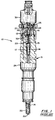
- the injector 10' of Figures 2 and 3 has an injector body 24' which includes an apertured nozzle 22' at one end thereof and a movable member bearing-surface 13 within an interior cavity 15' of injector body 24'.
- the injector 10' further comprises a movable needle valve assembly 14' disposed within the interior cavity 15' of injector body 24' for linear reciprocal movement between fuel-blocking and fuel-injection positions.
- the portion of interior cavity 15' which is not occupied by needle assembly 14' contains high pressure fuel from a common rail fuel supply as is conventional in the art.
- Needle assembly 14' also preferably includes an annular trough 40 which is disposed opposite bearing surface 13 of body 24'.
- Trough 40 thus, includes a cylindrical surface 43 and first and second opposing hollow circular surfaces 41 and 42, respectively.
- Surfaces 41 through 43 of trough 40 provide movable-member bearing surfaces on needle assembly 14' and cradle movable members 50 therein.
- needle assembly 14' is preferably symmetric with respect to axis A.
- Injector 10' further comprises at least one inventive needle-guide which preferably includes a plurality of movable insulating guide members 50 not integral with (i.e, not fixedly attached to) either body 24' or needle valve 14'.
- movable members 50 typically experience rotational motion relative to needle valve 14 and rotational and longitudinal motion relative to body 24' during longitudinal movement of needle valve 14'.
- movable members 50 are preferably spherical in shape.
- movable members 50 are disposed between needle valve assembly 14' and injector body 24' such that needle valve assembly 14' is held in spaced relation to injector body 24' and such that fuel is free to pass through cavity 15' between injector body 24', needle valve assembly 14' and movable members 50.
- movable members 50 are preferably formed of discrete, solid spherical ceramic balls, a number of alternatives will be readily apparent to those of ordinary skill in the art.
- movable members 50 could be composed of a metallic core with a ceramic coating on the surface thereof.
- members 50 could be composed of a conductive core, such as a metallic core, with a coating of some other insulating material on the surface thereof.
- this insulating material could be diamond-like carbon (DLC), aluminum oxide or other similar materials known in the art.
- members 50 could be composed of solid ceramic balls with an additional layer of insulating and/or friction-reducing materials for still further improved performance.
- members 50 could include solid cylindrical movable members rather than spherical members.
- annular trough 40 would preferably be changed to a hollow-square style trough.
- trough 40 could take the form of a plurality of smaller discrete member-retaining troughs, each of which would retain at least one insulating member 50.
- the shape of bearing surface 13 would be changed to cooperate with members 50 accordingly (e.g., surface 13 could have planar bearing surfaces).
- the movable member trough could be formed in injector body 24' and a complimentary bearing surface could be provided on needle assembly 14'.
- annular trough 40 could be replaced by a plurality of discrete member-retaining troughs for retaining one or more of members 50.
- discrete guide-slots which extend parallel to axis A could be cut into bearing surface 13 in order to further guide the movement of members 50.
- inventive insulating guide could also be utilized in other locations along the length of needle assembly 14'. Additionally, it should be appreciated that, in applications requiring more than one needle-guide member, one or more of the inventive needle-guides could be combined with one or more of the conventional needle-guides discussed above.
- the present invention provides a fuel injector utilising at least one movable needle-guide to improve wear characteristics of the injector; and furthermore provides an improved fuel injector having an insulating needle-guide which utilises rotational motion to guide the needle valve during movement; and furthermore provides an improved fuel injector which offers improved long-term wear characteristics; and furthermore provides an improved fuel injector which utilises at least one ceramic insulating needle-guide; and furthermore provides an improved fuel injector which requires less stringent quality control standards during the manufacturing thereof and yet still results in a high quality fuel injector at minimum cost; and furthermore provides an improved fuel injector utilising at least one insulating needle-guide which permits fuel to freely pass between the needle valve assembly and injector body in the region of the insulating needle-guide; and furthermore provides an improved fuel injector which offers an optimal combination of injector (1) simplicity; (2) reliability; (3) efficiency; and (4) versatility.
Landscapes
- Engineering & Computer Science (AREA)
- Chemical & Material Sciences (AREA)
- Combustion & Propulsion (AREA)
- Mechanical Engineering (AREA)
- General Engineering & Computer Science (AREA)
- Physics & Mathematics (AREA)
- Fluid Mechanics (AREA)
- Fuel-Injection Apparatus (AREA)
Applications Claiming Priority (2)
| Application Number | Priority Date | Filing Date | Title |
|---|---|---|---|
| US09/067,299 US6062498A (en) | 1998-04-27 | 1998-04-27 | Fuel injector with at least one movable needle-guide |
| US67299 | 1998-04-27 |
Publications (1)
| Publication Number | Publication Date |
|---|---|
| EP0953762A2 true EP0953762A2 (de) | 1999-11-03 |
Family
ID=22075067
Family Applications (1)
| Application Number | Title | Priority Date | Filing Date |
|---|---|---|---|
| EP99303270A Withdrawn EP0953762A2 (de) | 1998-04-27 | 1999-04-27 | Kraftstoffinjektor mit mindestens einem bewegbaren Nadelführung |
Country Status (3)
| Country | Link |
|---|---|
| US (1) | US6062498A (de) |
| EP (1) | EP0953762A2 (de) |
| JP (1) | JPH11351104A (de) |
Cited By (3)
| Publication number | Priority date | Publication date | Assignee | Title |
|---|---|---|---|---|
| WO2005080786A1 (de) * | 2004-02-11 | 2005-09-01 | Siemens Aktiengesellschaft | Kontaktierung der ventilnadel eines injektors für verbrennungsmotoren |
| WO2017153064A1 (de) * | 2016-03-09 | 2017-09-14 | Robert Bosch Gmbh | Kraftstoffeinspritzventil |
| EP3346124A1 (de) * | 2014-07-22 | 2018-07-11 | Delphi International Operations Luxembourg S.à r.l. | Kraftstoffeinspritzer |
Families Citing this family (39)
| Publication number | Priority date | Publication date | Assignee | Title |
|---|---|---|---|---|
| DE19820513A1 (de) * | 1998-05-08 | 1999-11-11 | Mtu Friedrichshafen Gmbh | Kraftstoffeinspritzdüse für eine Brennkraftmaschine |
| US6802457B1 (en) * | 1998-09-21 | 2004-10-12 | Caterpillar Inc | Coatings for use in fuel system components |
| US6508416B1 (en) * | 2000-04-28 | 2003-01-21 | Delphi Technologies, Inc. | Coated fuel injector valve |
| JP2004028051A (ja) * | 2002-06-28 | 2004-01-29 | Denso Corp | 燃料噴射ノズルおよびその製造方法 |
| US6991219B2 (en) * | 2003-01-07 | 2006-01-31 | Ionbond, Llc | Article having a hard lubricious coating |
| US7249722B2 (en) | 2004-03-30 | 2007-07-31 | Stanadyne Corporation | Fuel injector with hydraulic flow control |
| JP5176337B2 (ja) * | 2006-05-12 | 2013-04-03 | 株式会社デンソー | 皮膜構造及びその形成方法 |
| US8561598B2 (en) | 2008-01-07 | 2013-10-22 | Mcalister Technologies, Llc | Method and system of thermochemical regeneration to provide oxygenated fuel, for example, with fuel-cooled fuel injectors |
| US8413634B2 (en) | 2008-01-07 | 2013-04-09 | Mcalister Technologies, Llc | Integrated fuel injector igniters with conductive cable assemblies |
| US8387599B2 (en) | 2008-01-07 | 2013-03-05 | Mcalister Technologies, Llc | Methods and systems for reducing the formation of oxides of nitrogen during combustion in engines |
| US8225768B2 (en) * | 2008-01-07 | 2012-07-24 | Mcalister Technologies, Llc | Integrated fuel injector igniters suitable for large engine applications and associated methods of use and manufacture |
| US8074625B2 (en) * | 2008-01-07 | 2011-12-13 | Mcalister Technologies, Llc | Fuel injector actuator assemblies and associated methods of use and manufacture |
| US7628137B1 (en) | 2008-01-07 | 2009-12-08 | Mcalister Roy E | Multifuel storage, metering and ignition system |
| US8635985B2 (en) | 2008-01-07 | 2014-01-28 | Mcalister Technologies, Llc | Integrated fuel injectors and igniters and associated methods of use and manufacture |
| US8365700B2 (en) | 2008-01-07 | 2013-02-05 | Mcalister Technologies, Llc | Shaping a fuel charge in a combustion chamber with multiple drivers and/or ionization control |
| EP2470485A4 (de) | 2009-08-27 | 2012-12-26 | Mcalister Technologies Llc | Keramikisolator sowie herstellungsverfahren und verwendungsverfahren dafür |
| CN102713244A (zh) | 2009-08-27 | 2012-10-03 | 麦卡利斯特技术有限责任公司 | 在具有多个驱动器和/或电离控制的燃烧室中成形供应燃料 |
| SG181526A1 (en) | 2009-12-07 | 2012-07-30 | Mcalister Technologies Llc | Integrated fuel injector igniters suitable for large engine applications and associated methods of use and manufacture |
| KR20120086375A (ko) | 2009-12-07 | 2012-08-02 | 맥알리스터 테크놀로지즈 엘엘씨 | 연료 인젝터 및 점화기를 위한 적응 제어 시스템 |
| US20110297753A1 (en) | 2010-12-06 | 2011-12-08 | Mcalister Roy E | Integrated fuel injector igniters configured to inject multiple fuels and/or coolants and associated methods of use and manufacture |
| CN102844540A (zh) | 2010-02-13 | 2012-12-26 | 麦卡利斯特技术有限责任公司 | 用于自适应地冷却发动机中的燃烧室的方法和系统 |
| US8205805B2 (en) | 2010-02-13 | 2012-06-26 | Mcalister Technologies, Llc | Fuel injector assemblies having acoustical force modifiers and associated methods of use and manufacture |
| US8528519B2 (en) | 2010-10-27 | 2013-09-10 | Mcalister Technologies, Llc | Integrated fuel injector igniters suitable for large engine applications and associated methods of use and manufacture |
| US8091528B2 (en) | 2010-12-06 | 2012-01-10 | Mcalister Technologies, Llc | Integrated fuel injector igniters having force generating assemblies for injecting and igniting fuel and associated methods of use and manufacture |
| US8820275B2 (en) | 2011-02-14 | 2014-09-02 | Mcalister Technologies, Llc | Torque multiplier engines |
| CN103890343B (zh) | 2011-08-12 | 2015-07-15 | 麦卡利斯特技术有限责任公司 | 用于改进的发动机冷却及能量产生的系统和方法 |
| US8919377B2 (en) | 2011-08-12 | 2014-12-30 | Mcalister Technologies, Llc | Acoustically actuated flow valve assembly including a plurality of reed valves |
| US8851047B2 (en) | 2012-08-13 | 2014-10-07 | Mcallister Technologies, Llc | Injector-igniters with variable gap electrode |
| US9169821B2 (en) | 2012-11-02 | 2015-10-27 | Mcalister Technologies, Llc | Fuel injection systems with enhanced corona burst |
| US9169814B2 (en) | 2012-11-02 | 2015-10-27 | Mcalister Technologies, Llc | Systems, methods, and devices with enhanced lorentz thrust |
| US8746197B2 (en) | 2012-11-02 | 2014-06-10 | Mcalister Technologies, Llc | Fuel injection systems with enhanced corona burst |
| US9309846B2 (en) | 2012-11-12 | 2016-04-12 | Mcalister Technologies, Llc | Motion modifiers for fuel injection systems |
| US9200561B2 (en) | 2012-11-12 | 2015-12-01 | Mcalister Technologies, Llc | Chemical fuel conditioning and activation |
| US9091238B2 (en) | 2012-11-12 | 2015-07-28 | Advanced Green Technologies, Llc | Systems and methods for providing motion amplification and compensation by fluid displacement |
| US9115325B2 (en) | 2012-11-12 | 2015-08-25 | Mcalister Technologies, Llc | Systems and methods for utilizing alcohol fuels |
| US8800527B2 (en) | 2012-11-19 | 2014-08-12 | Mcalister Technologies, Llc | Method and apparatus for providing adaptive swirl injection and ignition |
| US9194337B2 (en) | 2013-03-14 | 2015-11-24 | Advanced Green Innovations, LLC | High pressure direct injected gaseous fuel system and retrofit kit incorporating the same |
| US9562500B2 (en) | 2013-03-15 | 2017-02-07 | Mcalister Technologies, Llc | Injector-igniter with fuel characterization |
| US8820293B1 (en) | 2013-03-15 | 2014-09-02 | Mcalister Technologies, Llc | Injector-igniter with thermochemical regeneration |
Citations (2)
| Publication number | Priority date | Publication date | Assignee | Title |
|---|---|---|---|---|
| US4066059A (en) | 1976-01-02 | 1978-01-03 | Texaco Inc. | Fuel injection nozzle valve and ignition system |
| US4414845A (en) | 1981-05-06 | 1983-11-15 | Robert Bosch Gmbh | Fuel injection nozzle, particularly for diesel engines |
Family Cites Families (5)
| Publication number | Priority date | Publication date | Assignee | Title |
|---|---|---|---|---|
| US2750957A (en) * | 1951-04-10 | 1956-06-19 | Tavola Bruno | Injection valve |
| US3667684A (en) * | 1970-09-17 | 1972-06-06 | Barkas Werke Ifa Kom Fur Kraft | Fuel injection valve |
| US4181010A (en) * | 1978-06-29 | 1980-01-01 | General Motors Corporation | Injection timing nozzle |
| DE2939274A1 (de) * | 1979-09-28 | 1981-04-16 | Robert Bosch Gmbh, 7000 Stuttgart | Kraftstoff-einspritzduese von brennkraftmaschinen |
| GB8926478D0 (en) * | 1989-11-23 | 1990-01-10 | Lucas Ind Plc | Fuel injector |
-
1998
- 1998-04-27 US US09/067,299 patent/US6062498A/en not_active Expired - Fee Related
-
1999
- 1999-04-21 JP JP11152422A patent/JPH11351104A/ja active Pending
- 1999-04-27 EP EP99303270A patent/EP0953762A2/de not_active Withdrawn
Patent Citations (2)
| Publication number | Priority date | Publication date | Assignee | Title |
|---|---|---|---|---|
| US4066059A (en) | 1976-01-02 | 1978-01-03 | Texaco Inc. | Fuel injection nozzle valve and ignition system |
| US4414845A (en) | 1981-05-06 | 1983-11-15 | Robert Bosch Gmbh | Fuel injection nozzle, particularly for diesel engines |
Cited By (3)
| Publication number | Priority date | Publication date | Assignee | Title |
|---|---|---|---|---|
| WO2005080786A1 (de) * | 2004-02-11 | 2005-09-01 | Siemens Aktiengesellschaft | Kontaktierung der ventilnadel eines injektors für verbrennungsmotoren |
| EP3346124A1 (de) * | 2014-07-22 | 2018-07-11 | Delphi International Operations Luxembourg S.à r.l. | Kraftstoffeinspritzer |
| WO2017153064A1 (de) * | 2016-03-09 | 2017-09-14 | Robert Bosch Gmbh | Kraftstoffeinspritzventil |
Also Published As
| Publication number | Publication date |
|---|---|
| JPH11351104A (ja) | 1999-12-21 |
| US6062498A (en) | 2000-05-16 |
Similar Documents
| Publication | Publication Date | Title |
|---|---|---|
| US6062498A (en) | Fuel injector with at least one movable needle-guide | |
| US5607106A (en) | Low inertia, wear-resistant valve for engine fuel injection systems | |
| RU2193683C2 (ru) | Гидрораспределительный клапан | |
| US7506826B2 (en) | Injection valve with a corrosion-inhibiting, wear-resistant coating and method for the production thereof | |
| US5915352A (en) | In-cylinder fuel injection device and internal combustion engine mounting the same | |
| US6454239B1 (en) | Valve for controlling liquids | |
| US6464202B1 (en) | Valve for controlling liquids | |
| US6612508B2 (en) | Fuel injector | |
| US7309027B2 (en) | Fuel injector for internal combustion engines | |
| RU2224132C2 (ru) | Электромагнитный топливный инжектор для двигателей внутреннего сгорания | |
| US5975437A (en) | Fuel injector solenoid utilizing an apertured armature | |
| EP0483768B1 (de) | Zusammenbau des Kernes eines Elektromagnetes eines elektromagnetischen Brennstoffeinspritzventils für Verbrennungsmotoren | |
| US6732949B1 (en) | Fuel injection valve for internal combustion engines | |
| US5718385A (en) | Control arrangement for a fuel injection valve | |
| GB2367330A (en) | Common-rail fuel injector | |
| US6439483B2 (en) | Variable orifice electronically controlled common rail injector (VOECRRI) | |
| GB2364101A (en) | Pressure-controlled control part for common-rail fuel injectors | |
| US6848630B2 (en) | Stroke and pressure-controlled injector with double slide | |
| US7628344B2 (en) | Fuel injector with VOP loss resistant valve spring for emissions-compliant engine applications | |
| US6227174B1 (en) | Plunger-activated unit injector for internal combustion engines | |
| US6561223B2 (en) | Subdivided control valve body for injector control valve | |
| US6669108B2 (en) | Pressure-control injector for injecting fuel with a double valve | |
| KR20070102377A (ko) | 내연기관용 연료 분사기 | |
| JPH11229998A (ja) | 燃料噴射装置 | |
| KR100279466B1 (ko) | 디젤엔진용연료분사노즐 |
Legal Events
| Date | Code | Title | Description |
|---|---|---|---|
| PUAI | Public reference made under article 153(3) epc to a published international application that has entered the european phase |
Free format text: ORIGINAL CODE: 0009012 |
|
| AK | Designated contracting states |
Kind code of ref document: A2 Designated state(s): AT BE CH CY DE DK ES FI FR GB GR IE IT LI LU MC NL PT SE |
|
| AX | Request for extension of the european patent |
Free format text: AL;LT;LV;MK;RO;SI |
|
| STAA | Information on the status of an ep patent application or granted ep patent |
Free format text: STATUS: THE APPLICATION HAS BEEN WITHDRAWN |
|
| 18W | Application withdrawn |
Withdrawal date: 20020311 |