EP0953764A1 - Volumetrische Pumpe - Google Patents
Volumetrische Pumpe Download PDFInfo
- Publication number
- EP0953764A1 EP0953764A1 EP99107763A EP99107763A EP0953764A1 EP 0953764 A1 EP0953764 A1 EP 0953764A1 EP 99107763 A EP99107763 A EP 99107763A EP 99107763 A EP99107763 A EP 99107763A EP 0953764 A1 EP0953764 A1 EP 0953764A1
- Authority
- EP
- European Patent Office
- Prior art keywords
- piston
- seat
- volumetric pump
- valve
- duct
- Prior art date
- Legal status (The legal status is an assumption and is not a legal conclusion. Google has not performed a legal analysis and makes no representation as to the accuracy of the status listed.)
- Granted
Links
- 238000005086 pumping Methods 0.000 claims abstract description 27
- 230000005291 magnetic effect Effects 0.000 claims abstract description 8
- 239000012530 fluid Substances 0.000 claims abstract description 4
- 230000000284 resting effect Effects 0.000 claims abstract 2
- 238000004891 communication Methods 0.000 claims description 9
- 239000004020 conductor Substances 0.000 claims description 4
- 239000000463 material Substances 0.000 claims description 4
- 239000003302 ferromagnetic material Substances 0.000 claims description 3
- 230000000295 complement effect Effects 0.000 claims description 2
- 238000001914 filtration Methods 0.000 claims 1
- 239000010687 lubricating oil Substances 0.000 description 15
- 238000002485 combustion reaction Methods 0.000 description 8
- 239000003921 oil Substances 0.000 description 6
- 238000006073 displacement reaction Methods 0.000 description 4
- 238000004519 manufacturing process Methods 0.000 description 4
- 230000008901 benefit Effects 0.000 description 3
- 230000005611 electricity Effects 0.000 description 3
- 230000008878 coupling Effects 0.000 description 2
- 238000010168 coupling process Methods 0.000 description 2
- 238000005859 coupling reaction Methods 0.000 description 2
- 238000005461 lubrication Methods 0.000 description 2
- 230000009467 reduction Effects 0.000 description 2
- 230000009471 action Effects 0.000 description 1
- 238000010276 construction Methods 0.000 description 1
- 230000008602 contraction Effects 0.000 description 1
- 238000007599 discharging Methods 0.000 description 1
- 229920002457 flexible plastic Polymers 0.000 description 1
- 239000007769 metal material Substances 0.000 description 1
- 238000012986 modification Methods 0.000 description 1
- 230000004048 modification Effects 0.000 description 1
- 238000007789 sealing Methods 0.000 description 1
- 238000011144 upstream manufacturing Methods 0.000 description 1
Images
Classifications
-
- F—MECHANICAL ENGINEERING; LIGHTING; HEATING; WEAPONS; BLASTING
- F04—POSITIVE - DISPLACEMENT MACHINES FOR LIQUIDS; PUMPS FOR LIQUIDS OR ELASTIC FLUIDS
- F04B—POSITIVE-DISPLACEMENT MACHINES FOR LIQUIDS; PUMPS
- F04B17/00—Pumps characterised by combination with, or adaptation to, specific driving engines or motors
- F04B17/03—Pumps characterised by combination with, or adaptation to, specific driving engines or motors driven by electric motors
- F04B17/04—Pumps characterised by combination with, or adaptation to, specific driving engines or motors driven by electric motors using solenoids
- F04B17/046—Pumps characterised by combination with, or adaptation to, specific driving engines or motors driven by electric motors using solenoids the fluid flowing through the moving part of the motor
-
- F—MECHANICAL ENGINEERING; LIGHTING; HEATING; WEAPONS; BLASTING
- F01—MACHINES OR ENGINES IN GENERAL; ENGINE PLANTS IN GENERAL; STEAM ENGINES
- F01M—LUBRICATING OF MACHINES OR ENGINES IN GENERAL; LUBRICATING INTERNAL COMBUSTION ENGINES; CRANKCASE VENTILATING
- F01M1/00—Pressure lubrication
- F01M1/02—Pressure lubrication using lubricating pumps
- F01M2001/0207—Pressure lubrication using lubricating pumps characterised by the type of pump
- F01M2001/0223—Electromagnetic pumps
Definitions
- the present invention relates to a volumetric pump.
- the present invention relates to a volumetric pump designed to ensure the circulation of lubricating oil in a two-stroke internal combustion engine of known type; the use to which the details as follow make explicit reference without loss of their general nature thereby.
- such pumps generally comprise a valve-like body of essentially cylindrical form, and a ferromagnetic material piston installed to slide axially within a cylindrical seat formed in the valve-like body.
- the two axial ends of the cylindrical seat are in communication with atmosphere by way of two connecting ducts which extend inside the valve-like body, coaxially with the longitudinal axis of the valve-like body; while the two variable-volume chambers in which the piston subdivides the cylindrical seat, are in communication together through an axial duct formed in the body of the piston.
- the electromagnetically-actuated volumetric pumps also comprise an opposition spring, which is located inside one of the two variable-volume chambers of which the piston subdivides the cylindrical seat, in such a manner as to minimise the volume of the chamber not occupied by the spring; and a coil of electrically conductor material, which when an electrical current passes through, is able to generate a magnetic field able to oppose the force of the opposing spring, and to axially move the piston in such a way as to maximise the volume of the variable-volume chamber not containing the spring.
- the said chamber defines the pumping chamber of the volumetric pump.
- the aforementioned electromagnetically-actuated volumetric pumps are finally provided with an intake valve located along the axial duct formed in the body of the piston, and with a supply valve located along the duct which connects the pumping chamber, or the variable-volume chamber not containing the opposition spring, directly to atmosphere.
- the purpose of the present invention is to provide an electro-magnetically actuated volumetric pump able to ensure a extremely precise control of the oil capacity throughout the whole range of use of an internal combustion engine, with relatively low production costs.
- a volumetric pump having a valve-like body, and at least a piston mounted to slide axially within a seat formed in the valve-like body itself the said seat being in communication with atmosphere by way of a supply duct and an intake duct, and the said piston defining on the inside of the said seat at least a variable-volume pumping chamber;
- the volumetric pumps also comprising flexible means able to retain the said piston in a rest position in which it minimises the volume of the said pumping chamber, a coil of electrically conductive material able to produce, on being supplied with a magnetic field able to axially displace the piston inside the said seat to produce a volume variation of the said pumping chamber, and at least an intake valve and a discharge valve able to regulate the fluid flow respectively on entry and on discharge from the said seat;
- the said volumetric pump being characterised by the fact that the said intake valve is located inside the pumping chamber and is not carried by the said piston.
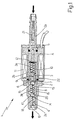
- reference number 1 indicates the whole of a volumetric pump assembly able to be used, preferably though not necessarily, to circulate the lubricating oil in a two-stroke internal combustion engine.
- the volumetric pump 1 comprises a valve-like body 2 of essentially cylindrical form, which extends coaxially with a longitudinal axis A, and has internally a seat 3 which extends preferably, though not necessarily, coaxially with axis A, and a pair of ducts 4 and 5 able to bring into communication the two axial ends of the seat 3 itself with atmosphere.
- the volumetric pump 1 also comprises a piston 6 made of ferromagnetic material, which is located axially mobile within the seat 3 formed in the valve-like body 2, and defines inside the seat 3 itself a variable volume pumping chamber 8. Obviously the connection between the piston 6 and the seat 3 has a fluid-proof seal.
- the duct 4 communicates directly with the chamber 8, and defines the volumetric pump supply duct 1, whereas duct 5 communicates with the seat 3 of the opposing part of the chamber 8 in relation to the piston 6, and defines the intake duct of the volumetric pump 1.
- ducts 4 and 5 extend coaxially with the axis A running in opposition to the seat 3 in such a way that each ends correspondingly in a respective end of the valve-like body 2.
- Such ends are designed in such a way as to allow coupling to pipework in which the lubricating oil circulates.
- the piston 6 has a passing hole 9, which extends coaxially with the axis A along the whole length of the piston 6 itself, in such a way as to ensure the communication of the chamber 8 with the duct 5.
- the volumetric pump 1 finally comprises a retaining spring 10 able to retain the piston 6 in a rest position in which, the piston 6 minimises the volume of the chamber 8, and a coil 11 made of electrically conducting material placed coaxially with axis A, on the outside of the valve-like body 2.
- the said coil 11 is able to generate when energised with electricity, a magnetic field and is located on the valve-like body 2 in such a manner that the magnetic field produced thereby causes an axial movement of the piston 6 so as to displace the piston 6 itself from the rest position, thus increasing the volume of chamber 8.
- the said displacement yes place against the action of spring 10.
- the seat 3 is sub-divided in two portions 3a and 3b of differing diameter, the piston 6 being mounted to slide within portion 3a of greater diameter, whereas the chamber 8 comprises the portion 3b of the seat 3 and as is more clearly explained below, part of the portion 3a when it reaches its maximum volume.
- the spring (70) on the other hand is located coaxially with the axis A inside the portion 3a of the part opposing the chamber 8 in relation to the piston 6 and presents a first end bearing against the piston 6 and a second end bearing against the bottom of the seat 3, in such a manner as to maintain the piston 6 bearing against the shoulder 7 connecting portions 3a and 3b of the seat 3 one to the other, or in the rest position.
- the volumetric pump 1 also has a disc 12 with a calibrated centre hole, which is located coaxially with the axis A in such a way as to present the calibrated hole aligned with the duct 5.
- the volumetric pump 1 also includes an intake valve 13 able to regulate the access of lubrication oil to the inside of the chamber 8, and a discharge valve 14 able to regulate the exit of the lubricating oil from the chamber 8.
- the intake valve 13 is located inside the chamber 8, to coincide with the passing hole 9 of the piston 6, whereas the discharge valve 14 is located in the duct 4 immediately downstream from the chamber 8.
- the valve 13 has a plug 15 located axially sliding inside the chamber 8, and an opposing spring 16 located inside the chamber 8 coaxially with axis A, with a first end bearing against the plug 15 and a second end bearing against the wall of the valve-like body 2, in such a manner as to maintain the plug 15 bearing on the piston 6 in such a way as to prevent with a fluid-sealing means the ingress from the passing hole 9.
- the valve 14 comprises instead a plug 17 located axially sliding inside the duct 4, and an opposing spring 18 located inside the duct 4 coaxially with the axis A, with a first end bearing against the plug 17 and a second end bearing against an annular shoulder 19 located inside the duct 5, in such a way as to keep the plug 17 bearing against a contraction 20 located at inlet of duct 5.
- both the plug 15 as well as the plug 17 consist of a metallic material spherically-formed body.
- volumetric pump 1 is preferably though not necessarily, fitted with a filter component 21 installed inside the duct 5.
- the valve body 2 consists of three cylindrical portions, respectively referenced 2a, 2b, 2c, in line along axis A, and made integral with each other by an external shell 22 which extends coaxially to axis A to protect the coil 11.
- the duct 5 is achieved inside the cylindrical portion 2a
- the seat 3 is achieved inside the cylindrical portion 2b
- the duct 4 is achieved inside the cylindrical portion 2c.
- volumetric pump 1 Operation of the volumetric pump 1 is now described assuming that the pump is located along a lubricating oil circulation duct.
- the opposing spring 16 nevertheless does not manage to keep the plug 15 bearing against piston 6, owing either to the inertia of the plug 15 or to the discharging lubricating oil forced through the passing hole (9).
- the lubricating oil occupying the portion 3a of the seat 3 together with the piston 6, in fact will discharge more easily through the passing hole (9) formed in the piston 6 than through the calibrated hole in the disc 12, also facilitated in this by the depression which occurs inside the chamber 8 owing to the rapid increase in volume.
- the opposing spring 18 ensures the return of the plug 17 to bear against the throttle 20 produced at the point of inlet of the duct 5.
- the capacity of the volumetric pump 1 is a function of the frequency with which the piston 6 is displaced inside the seat 3, that is to say of the frequency with which an electric current is made to pass through the coil 11.
- the piston 6 is made of permanent magnet material.
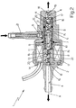
- the piston 6 is double acting, and defines inside its seat two variable volume pumping chambers 9 complementary to each other.
- Each chamber 8 is connected with atmosphere through a supply duct 4 which extends coaxial with the axis A, and has an intake valve 13 and a discharge valve 14, whereas the intake duct 5 is in common communication with both chambers 9, and extends inside the valve-like body 2 perpendicularly to the axis A, along an appendix of the valve body 2 which in turn extends perpendicularly to axis A.
- the duct 5 faces a branch 9a of the passing hole 9 which extends in the piston 6 perpendicularly to axis A, and the disc 12 is located along the duct 5, immediately upstream from the seat 3.
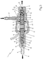
- valve body 2 presents two seats 3 each of which is actuated in a sliding manner by a respective piston 6, which defines a pumping chamber 8.
- each chamber 8 is connected to atmosphere through a supply duct 4 which extends coaxial to the axis A, and is provided with its own intake valve 13 and its own discharge valve 14.
- the intake duct 5 is in communication with both seats 3, and a terminal portion thereof extends into the valve body 2 coaxially to the axis A, along an appendix in the valve body 2 which extends in turn, perpendicularly to axis A.
- volumetric pump 1 The advantages of the volumetric pump 1 described above and as shown are evident: the absence of the intake valve 13 on the piston allows a drastic reduction in its weight with a considerable increase in maximum capacity of the pump related to solutions at present adopted.
- a further advantage derives from the fact that the plug 15 for valve 13 cannot be deformed so that the volume of the chamber 8 is constant in whatsoever operating condition.
- the volumetric pump 1 can thus be transformed into a metering arrangement always able to provide the same volume of oil under pressure on each electrical current impulse.
- volumetric pump 1 has extremely simple construction, with a limited number of component parts in relative movement, and the fact that it allows direct piloting from an electronic central unit which, by varying the frequency of the supply to the coil 11, it is possible to control in real time and with extreme precision the capacity thus provided.
- volumetric pump 1 described and illustrated herein without thereby exceeding the scope of the present invention.
Landscapes
- Engineering & Computer Science (AREA)
- Physics & Mathematics (AREA)
- Fluid Mechanics (AREA)
- Mechanical Engineering (AREA)
- General Engineering & Computer Science (AREA)
- Details Of Reciprocating Pumps (AREA)
- Lubrication Of Internal Combustion Engines (AREA)
- Reciprocating Pumps (AREA)
Applications Claiming Priority (2)
| Application Number | Priority Date | Filing Date | Title |
|---|---|---|---|
| ITBO980263 | 1998-04-27 | ||
| IT98BO000263A IT1299987B1 (it) | 1998-04-27 | 1998-04-27 | Pompa volumetrica. |
Publications (2)
| Publication Number | Publication Date |
|---|---|
| EP0953764A1 true EP0953764A1 (de) | 1999-11-03 |
| EP0953764B1 EP0953764B1 (de) | 2004-09-29 |
Family
ID=11343135
Family Applications (1)
| Application Number | Title | Priority Date | Filing Date |
|---|---|---|---|
| EP99107763A Expired - Lifetime EP0953764B1 (de) | 1998-04-27 | 1999-04-19 | Volumetrische Pumpe |
Country Status (4)
| Country | Link |
|---|---|
| EP (1) | EP0953764B1 (de) |
| DE (1) | DE69920566T2 (de) |
| ES (1) | ES2229574T3 (de) |
| IT (1) | IT1299987B1 (de) |
Cited By (7)
| Publication number | Priority date | Publication date | Assignee | Title |
|---|---|---|---|---|
| EP1001167A3 (de) * | 1998-11-13 | 2000-11-15 | Mikuniadec Corporation | Elektromagnetische Pumpe |
| EP1236894A1 (de) * | 2001-03-01 | 2002-09-04 | Dell'orto S.P.A. | Elektromagnetische Pumpe |
| EP1236895A1 (de) * | 2001-03-01 | 2002-09-04 | Dell'orto S.P.A. | Elektromagnetische Pumpe |
| EP1227242A3 (de) * | 2001-01-24 | 2003-06-11 | Mikuniadec Corporation | Kraftstoffförderpumpe |
| EP1319832A3 (de) * | 2001-12-13 | 2004-01-21 | Dell'orto S.P.A. | Elektromagnetische Pumpe |
| EP1717439A1 (de) * | 2005-04-18 | 2006-11-02 | Dell'orto S.P.A. | Brennstoffeinspritzsystem für Brennkraftmaschine |
| WO2019114904A1 (en) | 2017-12-13 | 2019-06-20 | Hans Jensen Lubricators A/S | Large slow-running two-stroke engine and method of lubricating such engine, as well as an injector with an electric pumping system for such engine and method |
Citations (4)
| Publication number | Priority date | Publication date | Assignee | Title |
|---|---|---|---|---|
| FR2465903A1 (fr) * | 1979-07-16 | 1981-03-27 | Ulka Srl | Pompe alternative electro-magnetique a piston |
| EP0288216A1 (de) * | 1987-04-15 | 1988-10-26 | Eaton S.A.M. | Elektrische Flüssigkeitspumpe |
| CH675312A5 (en) * | 1988-06-13 | 1990-09-14 | Rueck & Meier Ag | Fluid dosing device using timed pump operation - compensates set time for detected variation in pump flow |
| US5567131A (en) * | 1995-04-20 | 1996-10-22 | Gorman-Rupp Industries | Spring biased check valve for an electromagnetically driven oscillating pump |
-
1998
- 1998-04-27 IT IT98BO000263A patent/IT1299987B1/it active IP Right Grant
-
1999
- 1999-04-19 EP EP99107763A patent/EP0953764B1/de not_active Expired - Lifetime
- 1999-04-19 DE DE69920566T patent/DE69920566T2/de not_active Expired - Fee Related
- 1999-04-19 ES ES99107763T patent/ES2229574T3/es not_active Expired - Lifetime
Patent Citations (4)
| Publication number | Priority date | Publication date | Assignee | Title |
|---|---|---|---|---|
| FR2465903A1 (fr) * | 1979-07-16 | 1981-03-27 | Ulka Srl | Pompe alternative electro-magnetique a piston |
| EP0288216A1 (de) * | 1987-04-15 | 1988-10-26 | Eaton S.A.M. | Elektrische Flüssigkeitspumpe |
| CH675312A5 (en) * | 1988-06-13 | 1990-09-14 | Rueck & Meier Ag | Fluid dosing device using timed pump operation - compensates set time for detected variation in pump flow |
| US5567131A (en) * | 1995-04-20 | 1996-10-22 | Gorman-Rupp Industries | Spring biased check valve for an electromagnetically driven oscillating pump |
Cited By (7)
| Publication number | Priority date | Publication date | Assignee | Title |
|---|---|---|---|---|
| EP1001167A3 (de) * | 1998-11-13 | 2000-11-15 | Mikuniadec Corporation | Elektromagnetische Pumpe |
| EP1227242A3 (de) * | 2001-01-24 | 2003-06-11 | Mikuniadec Corporation | Kraftstoffförderpumpe |
| EP1236894A1 (de) * | 2001-03-01 | 2002-09-04 | Dell'orto S.P.A. | Elektromagnetische Pumpe |
| EP1236895A1 (de) * | 2001-03-01 | 2002-09-04 | Dell'orto S.P.A. | Elektromagnetische Pumpe |
| EP1319832A3 (de) * | 2001-12-13 | 2004-01-21 | Dell'orto S.P.A. | Elektromagnetische Pumpe |
| EP1717439A1 (de) * | 2005-04-18 | 2006-11-02 | Dell'orto S.P.A. | Brennstoffeinspritzsystem für Brennkraftmaschine |
| WO2019114904A1 (en) | 2017-12-13 | 2019-06-20 | Hans Jensen Lubricators A/S | Large slow-running two-stroke engine and method of lubricating such engine, as well as an injector with an electric pumping system for such engine and method |
Also Published As
| Publication number | Publication date |
|---|---|
| DE69920566T2 (de) | 2005-12-08 |
| ES2229574T3 (es) | 2005-04-16 |
| ITBO980263A0 (it) | 1998-04-27 |
| IT1299987B1 (it) | 2000-04-04 |
| ITBO980263A1 (it) | 1999-10-27 |
| DE69920566D1 (de) | 2004-11-04 |
| EP0953764B1 (de) | 2004-09-29 |
Similar Documents
| Publication | Publication Date | Title |
|---|---|---|
| US5797732A (en) | Variable capacity pump having a pressure responsive relief valve arrangement | |
| US5547349A (en) | Oil pump system | |
| US6824120B2 (en) | Flow amount control device | |
| EP3071836B1 (de) | Schmiermittelverstellpumpe | |
| US5413077A (en) | Non-return fuel system with fuel pressure vacuum response | |
| CN110714809B (zh) | 用于内燃机的曲轴箱通风的系统 | |
| US20170167329A1 (en) | Systems and methods for fluid pump outlet pressure regulation | |
| EP0953764B1 (de) | Volumetrische Pumpe | |
| US5156531A (en) | Radial piston pump | |
| CN109139246B (zh) | 用于控制可变压缩内燃机连杆液压流体流的转换阀及连杆 | |
| JP5584313B2 (ja) | タンクから内燃機関へと燃料を供給するシステム | |
| US4840112A (en) | Combined valve/cylinder using electro-rheological fluid | |
| CN112576487A (zh) | 直列式活塞泵 | |
| JPH0968127A (ja) | 燃料供給装置 | |
| US9004884B2 (en) | In-tank fluid transfer assembly | |
| CN111173916B (zh) | 用于机动车变速器的液压系统的冷却优先阀 | |
| US8257062B2 (en) | Electric thrust piston pump device | |
| CN215927966U (zh) | 液压阀和液压装置及液压系统 | |
| CN111237538A (zh) | 发动机活塞冷却系统大流量智能控制电磁阀 | |
| US5800139A (en) | Electromagnetic oil pump | |
| CN110469503B (zh) | 一种基于变排量泵的两级变量控制系统 | |
| WO2007122463A2 (en) | A pressure dissipater device for a hydraulic circuit | |
| CN112196751A (zh) | 一种柱塞泵 | |
| CN210034599U (zh) | 一种比例减压阀 | |
| CA1150590A (en) | Flow and pressure compensated valves and pump circuits incorporating the same |
Legal Events
| Date | Code | Title | Description |
|---|---|---|---|
| PUAI | Public reference made under article 153(3) epc to a published international application that has entered the european phase |
Free format text: ORIGINAL CODE: 0009012 |
|
| AK | Designated contracting states |
Kind code of ref document: A1 Designated state(s): DE ES FR GB IT |
|
| AX | Request for extension of the european patent |
Free format text: AL;LT;LV;MK;RO;SI |
|
| 17P | Request for examination filed |
Effective date: 19991118 |
|
| AKX | Designation fees paid |
Free format text: DE ES FR GB IT |
|
| 17Q | First examination report despatched |
Effective date: 20021205 |
|
| GRAP | Despatch of communication of intention to grant a patent |
Free format text: ORIGINAL CODE: EPIDOSNIGR1 |
|
| GRAS | Grant fee paid |
Free format text: ORIGINAL CODE: EPIDOSNIGR3 |
|
| GRAA | (expected) grant |
Free format text: ORIGINAL CODE: 0009210 |
|
| RAP1 | Party data changed (applicant data changed or rights of an application transferred) |
Owner name: MAGNETI MARELLI POWERTRAIN S.P.A. |
|
| AK | Designated contracting states |
Kind code of ref document: B1 Designated state(s): DE ES FR GB IT |
|
| REG | Reference to a national code |
Ref country code: GB Ref legal event code: FG4D |
|
| REF | Corresponds to: |
Ref document number: 69920566 Country of ref document: DE Date of ref document: 20041104 Kind code of ref document: P |
|
| REG | Reference to a national code |
Ref country code: ES Ref legal event code: FG2A Ref document number: 2229574 Country of ref document: ES Kind code of ref document: T3 |
|
| ET | Fr: translation filed | ||
| PLBE | No opposition filed within time limit |
Free format text: ORIGINAL CODE: 0009261 |
|
| STAA | Information on the status of an ep patent application or granted ep patent |
Free format text: STATUS: NO OPPOSITION FILED WITHIN TIME LIMIT |
|
| 26N | No opposition filed |
Effective date: 20050630 |
|
| PGFP | Annual fee paid to national office [announced via postgrant information from national office to epo] |
Ref country code: ES Payment date: 20080430 Year of fee payment: 10 |
|
| PGFP | Annual fee paid to national office [announced via postgrant information from national office to epo] |
Ref country code: IT Payment date: 20080422 Year of fee payment: 10 |
|
| PGFP | Annual fee paid to national office [announced via postgrant information from national office to epo] |
Ref country code: DE Payment date: 20080623 Year of fee payment: 10 |
|
| PGFP | Annual fee paid to national office [announced via postgrant information from national office to epo] |
Ref country code: GB Payment date: 20080417 Year of fee payment: 10 |
|
| GBPC | Gb: european patent ceased through non-payment of renewal fee |
Effective date: 20090419 |
|
| REG | Reference to a national code |
Ref country code: FR Ref legal event code: ST Effective date: 20091231 |
|
| PG25 | Lapsed in a contracting state [announced via postgrant information from national office to epo] |
Ref country code: DE Free format text: LAPSE BECAUSE OF NON-PAYMENT OF DUE FEES Effective date: 20091103 |
|
| PG25 | Lapsed in a contracting state [announced via postgrant information from national office to epo] |
Ref country code: GB Free format text: LAPSE BECAUSE OF NON-PAYMENT OF DUE FEES Effective date: 20090419 Ref country code: FR Free format text: LAPSE BECAUSE OF NON-PAYMENT OF DUE FEES Effective date: 20091222 |
|
| PGFP | Annual fee paid to national office [announced via postgrant information from national office to epo] |
Ref country code: FR Payment date: 20080423 Year of fee payment: 10 |
|
| REG | Reference to a national code |
Ref country code: ES Ref legal event code: FD2A Effective date: 20090420 |
|
| PG25 | Lapsed in a contracting state [announced via postgrant information from national office to epo] |
Ref country code: ES Free format text: LAPSE BECAUSE OF NON-PAYMENT OF DUE FEES Effective date: 20090420 |
|
| PG25 | Lapsed in a contracting state [announced via postgrant information from national office to epo] |
Ref country code: IT Free format text: LAPSE BECAUSE OF NON-PAYMENT OF DUE FEES Effective date: 20090419 |