EP0953781B1 - Magnetlager - Google Patents
Magnetlager Download PDFInfo
- Publication number
- EP0953781B1 EP0953781B1 EP99108299A EP99108299A EP0953781B1 EP 0953781 B1 EP0953781 B1 EP 0953781B1 EP 99108299 A EP99108299 A EP 99108299A EP 99108299 A EP99108299 A EP 99108299A EP 0953781 B1 EP0953781 B1 EP 0953781B1
- Authority
- EP
- European Patent Office
- Prior art keywords
- magnetic
- electromagnet
- magnetic flux
- flux density
- rotor
- Prior art date
- Legal status (The legal status is an assumption and is not a legal conclusion. Google has not performed a legal analysis and makes no representation as to the accuracy of the status listed.)
- Expired - Lifetime
Links
Images













Classifications
-
- F—MECHANICAL ENGINEERING; LIGHTING; HEATING; WEAPONS; BLASTING
- F04—POSITIVE - DISPLACEMENT MACHINES FOR LIQUIDS; PUMPS FOR LIQUIDS OR ELASTIC FLUIDS
- F04D—NON-POSITIVE-DISPLACEMENT PUMPS
- F04D29/00—Details, component parts, or accessories
- F04D29/05—Shafts or bearings, or assemblies thereof, specially adapted for elastic fluid pumps
- F04D29/056—Bearings
- F04D29/058—Bearings magnetic; electromagnetic
-
- F—MECHANICAL ENGINEERING; LIGHTING; HEATING; WEAPONS; BLASTING
- F04—POSITIVE - DISPLACEMENT MACHINES FOR LIQUIDS; PUMPS FOR LIQUIDS OR ELASTIC FLUIDS
- F04D—NON-POSITIVE-DISPLACEMENT PUMPS
- F04D19/00—Axial-flow pumps
- F04D19/02—Multi-stage pumps
- F04D19/04—Multi-stage pumps specially adapted to the production of a high vacuum, e.g. molecular pumps
- F04D19/048—Multi-stage pumps specially adapted to the production of a high vacuum, e.g. molecular pumps comprising magnetic bearings
-
- F—MECHANICAL ENGINEERING; LIGHTING; HEATING; WEAPONS; BLASTING
- F16—ENGINEERING ELEMENTS AND UNITS; GENERAL MEASURES FOR PRODUCING AND MAINTAINING EFFECTIVE FUNCTIONING OF MACHINES OR INSTALLATIONS; THERMAL INSULATION IN GENERAL
- F16C—SHAFTS; FLEXIBLE SHAFTS; ELEMENTS OR CRANKSHAFT MECHANISMS; ROTARY BODIES OTHER THAN GEARING ELEMENTS; BEARINGS
- F16C32/00—Bearings not otherwise provided for
- F16C32/04—Bearings not otherwise provided for using magnetic or electric supporting means
- F16C32/0406—Magnetic bearings
- F16C32/044—Active magnetic bearings
- F16C32/0459—Details of the magnetic circuit
-
- F—MECHANICAL ENGINEERING; LIGHTING; HEATING; WEAPONS; BLASTING
- F16—ENGINEERING ELEMENTS AND UNITS; GENERAL MEASURES FOR PRODUCING AND MAINTAINING EFFECTIVE FUNCTIONING OF MACHINES OR INSTALLATIONS; THERMAL INSULATION IN GENERAL
- F16C—SHAFTS; FLEXIBLE SHAFTS; ELEMENTS OR CRANKSHAFT MECHANISMS; ROTARY BODIES OTHER THAN GEARING ELEMENTS; BEARINGS
- F16C32/00—Bearings not otherwise provided for
- F16C32/04—Bearings not otherwise provided for using magnetic or electric supporting means
- F16C32/0406—Magnetic bearings
- F16C32/044—Active magnetic bearings
- F16C32/0459—Details of the magnetic circuit
- F16C32/0461—Details of the magnetic circuit of stationary parts of the magnetic circuit
- F16C32/0465—Details of the magnetic circuit of stationary parts of the magnetic circuit with permanent magnets provided in the magnetic circuit of the electromagnets
-
- F—MECHANICAL ENGINEERING; LIGHTING; HEATING; WEAPONS; BLASTING
- F16—ENGINEERING ELEMENTS AND UNITS; GENERAL MEASURES FOR PRODUCING AND MAINTAINING EFFECTIVE FUNCTIONING OF MACHINES OR INSTALLATIONS; THERMAL INSULATION IN GENERAL
- F16C—SHAFTS; FLEXIBLE SHAFTS; ELEMENTS OR CRANKSHAFT MECHANISMS; ROTARY BODIES OTHER THAN GEARING ELEMENTS; BEARINGS
- F16C2360/00—Engines or pumps
- F16C2360/44—Centrifugal pumps
-
- F—MECHANICAL ENGINEERING; LIGHTING; HEATING; WEAPONS; BLASTING
- F16—ENGINEERING ELEMENTS AND UNITS; GENERAL MEASURES FOR PRODUCING AND MAINTAINING EFFECTIVE FUNCTIONING OF MACHINES OR INSTALLATIONS; THERMAL INSULATION IN GENERAL
- F16C—SHAFTS; FLEXIBLE SHAFTS; ELEMENTS OR CRANKSHAFT MECHANISMS; ROTARY BODIES OTHER THAN GEARING ELEMENTS; BEARINGS
- F16C2360/00—Engines or pumps
- F16C2360/44—Centrifugal pumps
- F16C2360/45—Turbo-molecular pumps
Definitions
- the present invention relates to a magnetic bearing spindle for use in manufacturing processing machinery (for metal molding or aluminum processing such as scrolling), a turbo molecular pump of semiconductor equipment or the like.
- the high-speed cutting is expected to produce the effects of improving the production efficiency, improving the processing accuracy and prolonging the operating life of the tool by virtue of a reduction in cutting resistance, reducing the cost of the mold and the like and reducing the processing time by virtue of cutting from an integrated material into a shape in a stroke.
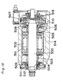
- Fig. 15 illustrates an example of the magnetic bearing spindle, in which are shown a spindle main shaft 500, a motor rotor 501, and a motor stator 502. There are also shown front side radial bearings 503 and 504, rear side radial bearings 505 and 506, and thrust bearings 507 and 508, these combinations each being constructed of the rotor located on the rotating side and the stator located on the stationary side. There are further shown radial displacement sensors 509 and 510 located on the front and rear sides, respectively, a thrust displacement sensor 511, protecting bearings 512 and 513, and a casing 514.
- spindle diameter spindle diameter ⁇ number of revolutions
- Document US 5 319 273 A as well as document US 4 504 098 A discloses a conventional radial magnetic bearing with eight poles around its circumference.
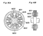
- Figs. 16A and 16B show the principle of a radial bearing similar to the bearing known from US 4 504 098 A, where are shown a rotor iron core 600 (corresponding to 503 of Fig. 15) constructed of electromagnetic steel plates, a stator iron core 601 (corresponding to 504 of Fig. 15), and a winding 602.
- the flow of magnetic flux is indicated by the arrow 603.
- the rotor is retained at the center in a non-contact manner by attracting the rotor 600 by magnetic forces from vertical and horizontal directions.
- the rotor iron core 600 is normally made to have a laminate structure formed by stacking thin electromagnetic steel plates (silicon steel plates).
- an object of the present invention is to provide a magnetic bearing which can give radical solutions to the issues that have not been able to be solved by the aforementioned measures (1) through (3) in reducing the eddy current loss.
- a preferred embodiment is defined in claim 2, according to which an inclined surface is formed on the magnetic pole inner surface so that a magnetic path gap formed between the magnetic pole inner surface and the rotor becomes narrower in the circumferential direction from the magnetic pole end portion to the magnetic pole center portion in the circumferential direction and the magnetic pole inner surface is provided with a circle coaxial portion with the rotor so that a uniform magnetic path gap is maintained.
- the radial electromagnet may be constructed by a magnetic pole arrangement of an NSSN type, and the magnetic flux density has a distribution in which the magnetic flux density gradually increases in an interval from a midpoint of a boundary to the magnetic pole on a heteropolar side in the circumferential direction and a roughly flat distribution in an interval from a midpoint of a boundary to the magnetic pole on a homopolar side in the circumferential direction.
- the radial electromagnet may be constructed by a magnetic pole arrangement of an NSSN type, and assuming that a gap between an inner surface of the magnetic pole end portion on an heteropolar side adjacent to one magnetic pole and the rotor is ⁇ 1 and a gap between an inner surface of the magnetic pole end portion on a homopolar side and the rotor is ⁇ 2 , then there holds ⁇ 1 > ⁇ 2 .
- a portion that has a reduced magnetic path area may be provided for the magnetic pole in a magnetic circuit that extends from a winding portion to the magnetic pole end portion.
- the stator section may be constructed by a plurality of divided and assembled core pieces through a division method for dividing the stator section into the core pieces and assembling the stator section.
- the magnetic flux density distribution may be asymmetrical about the magnetic pole center portion in the circumferential direction.
- an interval on the entrance side of the magnetic pole having a distribution in which the magnetic flux density gradually increases from the magnetic pole end portion to the magnetic pole center portion in the circumferential direction is ⁇ 1
- an interval on the exit side of the magnetic pole having a distribution in which the magnetic flux density gradually decreases from the magnetic pole end portion to the magnetic pole center portion in the circumferential direction is ⁇ 2
- an angle that one magnetic pole bears as the radial electromagnet is ⁇ , then there may hold ( ⁇ 1 / ⁇ ) ⁇ ( ⁇ 2 / ⁇ ).
- shapes of the magnetic pole located on the heteropolar side and the magnetic pole located on the homopolar side of the magnetic pole or a relative positional relation between the magnetic pole located on the heteropolar side and the magnetic pole located on the homopolar side of a magnetic pole adjacent to the one magnetic pole may be asymmetrical.
- the magnetic flux density may be a distribution in which the magnetic flux density gradually increases in intervals in the circumferential direction from midpoints of boundaries to the magnetic poles on both the heteropolar side and the homopolar side, and assuming that the interval of increase on the heteropolar side is ⁇ 1 and the interval of increase on the homopolar side is ⁇ 2 , then there holds ⁇ 1 > ⁇ 2 .
- An inclined surface may be formed on an inner surface of the magnetic pole so that the magnetic path gap formed between the inner surface of the magnetic pole and the rotor is tapered down in the circumferential direction from the magnetic pole end portion on the heteropolar side toward the magnetic pole center portion in the circumferential direction.
- the inner surface of the magnetic pole center portion may be provided with a circle coaxial portion with the rotor so that a uniform magnetic path gap is maintained.
- a portion that has a reduced magnetic path area may be provided on the heteropolar side of the magnetic pole in a magnetic circuit that extends from a winding portion to the magnetic pole end portion.
- the stator section may be constructed of a plurality of core pieces.
- the magnetic bearing may be part of a rotary spindle comprising:
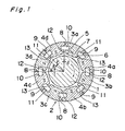
- Fig. 1 shows the principle of a radial magnetic bearing electromagnet (referred to as an electromagnet A) according to the first embodiment of the present invention.
- an electromagnet A a radial magnetic bearing electromagnet
- a rotor 1 and a stator section 2 employs the NSNS type structure constructed of eight independent magnetic poles. That is, four north poles 3a through 3d and four south poles 4a through 4d are arranged alternately in the circumferential direction.
- one north pole 3a there are shown inclined portions 5 and 6 formed at both end portions of the inner surface of the magnetic pole 3a, a perfect circle portion (coaxial portion) 7 arranged coaxially with the rotor 1, mutually engageable projected and recessed connecting portions 8 and 9 for positioning and fastening the respective magnetic poles, winding accommodating portions 10 and 11, and slot portions 12 and 13 that are inter-heteropolar gaps. It is to be noted that these portions 5 through 11 are similarly provided for each of the other magnetic poles.
- Fig. 2 shows an enlarged view of the magnetic pole 3a.
- the interval of the angle ⁇ is referred to as a rising interval (approaching interval) of a magnetic flux density curve and the interval of the angle ⁇ is referred to as a falling interval (decelerating interval).
- the inner surface of the magnetic pole is formed coaxially with the rotor 1, and a gap (air gap) between the rotor 1 and the magnetic pole is uniform.
- Fig. 17 is an example of the magnetic bearing spindle provided with the radial magnetic bearing electromagnet of the first embodiment, in which the magnetic bearing is a rotary spindle comprising:
- a rotor 81 and a stator section 82 This stator section 82 also has the NSNS type structure in which four north poles 83a through 83d and four south poles 84a through 84d are alternately arranged in the circumferential direction.
- one magnetic pole 83a there is a perfect circle portion 85, where the gap between the rotor 81 and each magnetic pole is uniform.
- winding accommodating portions 86 and 87, and slot portions 88 and 89 that are inter-heteropolar gaps.
- This arrangement is selected in order to compare the loss of the present invention with the loss of the conventional structure under the same conditions of loading capability and rigidity through the eddy current loss analysis as follows.
- Fig. 13 shows the principle of a radial magnetic bearing electromagnet C that has conventionally been generally used and which is similar to the bearing known from US 5 319 273 A.
- This stator section 702 also has the NSNS type structure in which four north poles 703a through 703d and four south poles 704a through 704d are alternately arranged in the circumferential direction.
- one magnetic pole 703a there is a perfect circle portion 705, where the gap between the rotor 701 and each magnetic pole is uniform.
- winding accommodating portions 706 and 707, and slot portions 708 and 709 that are inter-heteropolar gaps.
- the slot width is set sufficiently large in order to accommodate a winding in the winding accommodating portions 706 and 707.
- B 0 is the maximum value of the magnetic flux density.
- ⁇ represents an angular acceleration of the spindle
- r represents the radius of the main shaft
- ⁇ J - ⁇ ⁇ B ⁇ t
- ⁇ represents a conductivity
- t represents time.
- i indicates a direction of a vector in x-direction shown in Fig. 3
- j indicate a direction of a vector in y-direction shown in Fig. 3
- k indicate a direction of a vector in z-direction shown in Fig. 3
- Jx represents a current density in x-direction
- Jz represents a current density in z-direction
- ⁇ " (nabla) represents a differential operator.
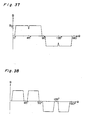
- the periodic function of the magnetic flux density distribution of the actual magnetic bearing has a close resemblance to a rectangular wave or a trapezoidal wave as shown in Fig. 4 or Fig. 12 respectively Fig. 37 or Fig. 38.
- a n represents a function of n obtained from Fourier-series by Fourier-series-approximating the periodic function.
- the eddy current loss W e in this case is expressed by the following equation: instead of the Equation 8.
- Equation 10 On the rotor surface of the magnetic bearing, the low frequency components of the magnetic flux enter the inside of the rotor, however, high frequency components are hard to enter. Therefore, assuming that a skin depth, i.e., a volume that causes a loss is proportional to: 1/ n then the Equation 10 becomes:
- a n represents the Fourier coefficient determined by the type (sine wave, trapezoidal wave, rectangular wave, or the like) of the periodic function.
- Fig. 5 shows the result of a relation between the eddy current loss and the length of the rising interval.
- the maximum value of the magnetic flux density of the electromagnet C that has a close resemblance to the rectangular wave is required to be increased as compared with the electromagnet A that has a close resemblance to the trapezoidal wave.
- the result (2) in Table 1 shows the corrected result.
- the embodiments of the present invention pays attention to the factor of the occurrence of the eddy current loss on the stator side of the stator, not on the rotor iron core side.
- the eddy current loss is attributed to the induction electromotive force generated as a consequence of variations in the direction and magnitude of the magnetic flux on the surface opposite to the magnetic poles of the rotor iron core.
- the current density of the eddy current attributed to this induction electromotive force is proportional to the amplitude of a variation in magnetic flux density. Therefore, the eddy current loss consumed by the rotor is proportional to the square of the current density, i.e., the square of the variation in magnetic flux density.
- a sudden change in magnetic flux density is caused by the relative movement of the rotor and the stator, and the sudden change has been the great factor of the eddy current loss.
- the magnetic flux density varies with a gentle slope when one point of the rotor shifts from N to S or from S to N. That is, by providing the magnetic flux density distribution with a sufficiently long rising interval (approaching interval) and a sufficiently long falling interval (decelerating interval) like a cam curve, the occurrence of eddy current loss is suppressed to allow the substantial reduction in heat generation.
- the provision of the magnetic flux density distribution with the rising interval and the falling interval is not just for the effect of reducing the loss.
- the loading capability and rigidity of the magnetic bearing are determined by the total area of the magnetic flux density distribution, and therefore, the present embodiment of which the magnetic flux density distribution has a close resemblance to the trapezoidal wave is advantageous since the present embodiment can provide a large total area as compared with the conventional magnetic bearing of which the magnetic flux density distribution has a close resemblance to the rectangular wave.
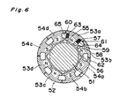
- Fig. 6 shows a second embodiment of the present invention, which is obtained by applying the present invention to the NSSN type magnetic pole arrangement.
- Fig. 7 shows the magnetic flux density distribution of the magnetic poles of Fig. 6.
- This stator section 52 is provided by the NSSN type constructed of eight independent magnetic poles. That is, the stator section is constructed of four north poles 53a through 53d and four south poles 54a through 54d, providing a construction in which a pair of adjacently arranged identical magnetic poles are alternately arranged in the circumferential direction.
- Fig. 8 shows an example in which a curved surface is formed on the magnetic pole inner surface of the aforementioned first embodiment. There are shown a magnetic pole 70, curved portions 71, and a perfect circle portion 72.
- the aforementioned embodiments are made to provide the magnetic flux density distribution with the rising and falling characteristics by forming the inclined surface on the magnetic pole inner surface and varying the gap (air gap) between the magnetic pole and the rotor in the circumferential direction.
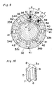
- Fig. 9 shows a third embodiment of the present invention.
- the magnetic flux density distribution is provided with rising and falling characteristics having a long interval by forming a portion of which the width (area) is reduced through a magnetic path extending from the winding portion to the magnetic pole end portion in the magnetic circuit formed in the order of, for example, north pole ⁇ air gap ⁇ rotor ⁇ air gap ⁇ south pole. Therefore, according to the present third embodiment, the inner surface shape of the magnetic pole is allowed to be coaxial with the rotor.
- This stator section 32 is provided by the NSNS type structure constructed of eight independent magnetic poles. That is, the stator section is constructed of four north poles 33a through 33d and four south poles 34a through 34d, which are alternately arranged in the circumferential direction.
- the stator section is constructed of four north poles 33a through 33d and four south poles 34a through 34d, which are alternately arranged in the circumferential direction.
- narrow portions having a reduced width in the circumferential direction of the magnetic path, i.e., air gap portions 35 and 36 between the inner surface on the magnetic pole rotor side and the winding accommodating portions 37 and 38.
- slot portions 39 and 40, and connecting portions 41 through 42 for positioning and fastening the respective magnetic poles.
- the magnetic path is provided with a portion of which the magnetic path width is reduced from d 1 to d 2 in the interval of the angle ⁇ along the path that extends from a point "a" at which a winding is peripherally wound to an end portion "b" of the magnetic pole.
- the width d 1 of the magnetic path is effective for conducting the magnetic flux.
- the magnetic flux density distribution by devising the shape of the magnetic path other than the portion of the magnetic pole that faces the rotor, e.g., by forming the narrow portion (air gap portion) in the magnetic path as described in connection with the third embodiment.
- the radial electromagnet is normally constructed of eight magnetic poles, and it is preferable to keep the thermal deformation of the spindle symmetrical about its axis by uniforming the loss (i.e., the calorific value) of each of the magnetic poles in order to ensure a high accuracy.
- pole division core method used for a motor is utilized for the stator of the magnetic bearing to which the present invention is applied, then magnetic poles of special shapes having a great face width, i.e., a small slot width and an inclined surface can be adopted.
- a winding process that has not been able to be performed in the conventional magnetic bearing electromagnet can be achieved by using the division method.
- each magnetic pole can be treated as a single unit, and therefore, a high-density winding can be provided fully in the space for accommodating the coil, also facilitating the laminating and assembling work. That is, by virtue of the permitted great face width of the electromagnet, the narrow portion (indicated by the reference numeral 35 in Fig. 9) for providing the inclined surface on the magnetic pole inner surface or the magnetic resistance with a distribution in the circumferential direction can be formed with sufficient margins in sufficiently long intervals. As a result, rising and falling intervals having sufficient lengths in the magnetic flux density can be provided, so that the substantial reduction of the loss can be achieved.
- Fig. 10 shows the shape of one magnetic pole in the case where the aforementioned processing method is used for the first embodiment (Fig. 1).
- a magnetic pole having an arbitrary shape can be adopted.
- the aforementioned division method is known in the field of the electric motor, there can be currently found no prior art to which the aforementioned processing method is applied to the magnetic bearing constructed of the magnetic poles having the specific shape intended for reducing the loss as proposed by the present embodiment.
- An example of the pole division method has the processes of dividing the stator into a plurality of core pieces, laminating high-precision core pieces by the intra-metal-mold laminate fixing method by means of, for example, laser, providing the pieces with high-density winding, and thereafter highly accurately recombining them together by means of laser.
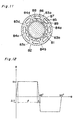
- a radial magnetic bearing electromagnet shown in Fig. 11, taken as a first comparative example.
- a rotor 81 and a stator section 82 This stator section 82 also has the NSNS type structure in which four north poles 83a through 83d and four south poles 84a through 84d are alternately arranged in the circumferential direction.
- a perfect circle portion 85 where a gap h 1 between the rotor 81 and the magnetic pole is uniform.
- winding accommodating portions 86 and 87, and slot portions 88 and 89 that are inter-heteropolar gaps.
- the magnetic flux is deformed by the influence of a diamagnetic field due to the eddy current on the rotor as a consequence of the high-speed rotation at the velocity of 40,000 rpm, so that the magnetic flux density distribution is sparse on the entrance side of the magnetic pole in the vicinity of the magnetic pole end portion by which one point on the rotor passes first and is dense on the exit side of the magnetic pole on the opposite side.
- Fig. 1 shows the principle of the radial magnetic bearing electromagnet of the first embodiment.
- the eddy current loss is attributed to the induction electromotive force generated due to a variation in the direction and magnitude of the magnetic flux in the surface of the rotor iron core opposite to the magnetic pole.
- the current density of the eddy current due to this induction electromotive force is proportional to the amplitude of the variation in magnetic flux density. Therefore, the eddy current loss consumed by the rotor 1 is proportional to the square of the current density, i.e., the square of the variation in magnetic flux density.
- the electromagnet of the first embodiment by providing such an electromagnet shape (with a taper) that the magnetic flux density varies with a gentle slope when one point of the rotor shifts from N to S or from S to N, the generation of the eddy current loss is suppressed to substantially reduce the heat generation.
- the total magnetic flux is reduced as compared with the first comparative example, it has been required to increase the maximum value of the magnetic flux density in order to generate the same attracting force as that of the first comparative example.
- As a measure for increasing the maximum value of the magnetic flux density there is, for example, a method for increasing the electromagnet current. However, the loss consequently increases.
- the fourth and fifth embodiments of the present invention pay attention to the fact that the generation of the eddy current comes to have an asymmetrical arrangement between the entrance side and the exit side (sparse on the entrance side and dense on the exit side of the magnetic pole) due to the effect of the dynamic magnetic field.
- the fourth and fifth embodiments forms the most appropriate shape for the eddy current loss and the attracting force by making the electromagnet shape asymmetrical about the magnetic pole center portion in the circumferential direction in order to form the electromagnet shape in correspondence with the variation in magnetic flux density, thereby allowing the eddy current loss to be reduced without reducing the attracting force.
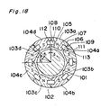
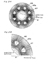
- Fig. 18 shows the principle of a radial magnetic bearing electromagnet (referred to as an electromagnet E) of the fourth embodiment of the present invention.
- electromagnet E a radial magnetic bearing electromagnet
- a rotor 101 and a stator section 102.
- This stator section 102 adopts the NSNS type structure constructed of eight independent magnetic poles. That is, four north poles 103a through 103d and four south poles 104a through 104d are arranged alternately in the circumferential direction.
- one north pole 103a there are shown inclined portions 105 and 106 formed at both end portions of the inner surface of the magnetic pole 103a, a perfect circle portion 107 arranged coaxially with the rotor 101, mutually engageable projected and recessed connecting portions 108 and 109 for positioning and fastening the respective magnetic poles, winding accommodating portions 110 and 111, and slot portions 112 and 113 that are inter-heteropolar gaps. It is to be noted that the portions 105 through 111 are similarly provided for the other magnetic poles.
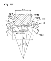
- Fig. 19 shows an enlarged view of part of the magnetic pole 103a of the fourth embodiment of the present invention.
- the interval of the angle ⁇ is referred to as a rising interval (approaching interval) of a magnetic flux density curve and the interval of the angle ⁇ is referred to as a falling interval (decelerating interval) thereof.
- the inner surface of the magnetic pole is formed coaxially with the rotor 101, and a gap (air gap) h 2 between the rotor 101 and the magnetic pole is uniform.
- the electromagnet shape is made asymmetrical about the magnetic pole center portion in the circumferential direction with the setting of ⁇ ⁇ ⁇ , and the gap (air gap) between the rotor 101 and the magnetic pole in the interval 107 of the angle ⁇ in the center portion is made small. That is, the above such shape is that the gap (air gap) between the rotor 101 and the magnetic pole in the interval 107 of the angle ⁇ in the center portion is made smaller than that of the first comparative example and the falling interval of the magnetic flux density on the exit side is further made longer than that of the first comparative example on the basis of the magnetic flux density distribution obtained through the dynamic magnetic field analysis.
- Fig. 11 shows the principle of a radial magnetic bearing electromagnet F in the case where both edge portions of the magnetic pole inner surface are provided with no inclined portion (taper portion).
- Fig. 2 shows the enlarged view of the magnetic pole 3a in the diagram of the principle of the first embodiment of Fig 1.
- the electromagnet of the first embodiment is called the electromagnet A.
- the magnetic pole inner surface is formed coaxially with the rotor 1, and the gap (air gap) h 1 between the rotor 1 and the magnetic pole is uniform.
- the dynamic magnetic field analysis for obtaining the magnetic flux density and the attracting force is performed on the fourth embodiment of the present invention using the aforementioned analysis model, and the electromagnet shape effective for the reduction of eddy current loss is obtained by comparison with the first comparative example and the first embodiment.
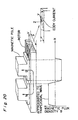
- Fig. 20 shows the state of the occurrence of an eddy current in the vicinity of the magnetic pole in the form of a model.
- the analytic results as described below are obtained by calculating the magnetic flux density and the attracting force through dynamic magnetic field analysis when the rotor is rotated in steps of a minute angle for one turn (360 degrees) on the aforementioned analytic conditions.
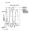
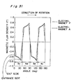
- Fig. 23 and Fig. 31 show the magnetic flux densities of the fourth embodiment of the present invention obtained through the dynamic magnetic field analysis by comparison with the electromagnet B of the first comparative example.
- the horizontal axis represents the angle from the slot center portion of the electromagnet, and the magnetic flux density within the angle of 180 degrees (corresponding to four poles of NSNS) is shown.
- each of the entrance and the exit of the magnetic flux density is made to have a gentle slope, and a greater total area is provided for the achievement of a magnetic bearing having small loss and high load capability. That is, according to Fig. 23, a gentle slope "a” can be given to the magnetic flux density B even though the rising interval ⁇ 1 is made small since the magnetic flux density B has a small absolute value in the entrance portion. A sufficiently gentle slope "b" is given to the exit portion by providing a sufficiently great interval ⁇ 2 since the magnetic flux density B has a great absolute value in the exit portion. As a result, sufficiently gentle slopes can be given to both the entrance and the exit even though the magnitude of the magnetic flux density B is totally increased for the increase of the loading capability. Therefore, the analytic results of Fig. 23 and Fig. 31 can be summarized as follows.
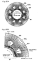
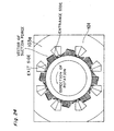
- Fig. 24, Fig. 30, and Fig. 32 show the attracting forces obtained through the dynamic magnetic field analysis.
- the magnitudes of the vectors in the figures represent the magnitudes of the attracting forces.
- the analytic results of Fig. 24, Fig. 30, and Fig. 32 can be summarized as follows.
- Fig. 24 shows the attracting forces of the electromagnet E.
- the electromagnet E has a wide region of the gentle slope portion with regard to the distribution of the attracting forces since a wide falling interval 105 is provided. Since the gap between the electromagnet and the rotor 101 in the flat portion 107 (interval ⁇ ) is made smaller than that of the electromagnet E, the attracting force in the flat portion 107 (interval ⁇ ) has a great absolute value of the attracting force, thereby compensating for the reduction in attracting force in the falling interval 105.
- Fig. 32 shows the attracting forces of the electromagnet A. As compared with the electromagnet F (Fig. 30) that has no inclined surface, the attracting force distribution has a gentle slope during the shift from N to S or from S to N. However, the absolute value of the attracting force is smaller than that of the electromagnet E.
- the fourth embodiment of the present invention suppresses the occurrence of eddy current loss by making the magnetic flux density shape have a gentle slope on the exit side (falling interval) of the magnetic pole where the magnetic flux density becomes dense.
- the fourth embodiment also reduces the gap between the electromagnet and the rotor in average by making the magnetic flux density shape have an inclination in a short interval on the entrance side of the magnetic pole where the magnetic flux density becomes sparse and the eddy current loss becomes small, thereby increasing the attracting forces.
- Fig. 25 shows the principle of the radial magnetic bearing electromagnet (referred to as an electromagnet G) according to the fifth embodiment of the present invention.
- an electromagnet G a rotor 21 and a stator section 22.
- This stator section 22 has the NSNS type structure constructed of eight independent magnetic poles. That is, four north poles 23a through 23d and four south poles 24a through 24d are arranged alternately in the circumferential direction.
- an inclined portion 25 formed at an end portion of the inner surface of the magnetic pole 23a, a perfect circle portion 26 arranged coaxially with the rotor 21, mutually engageable projected and recessed connecting portions 27 and 28 for positioning and fastening the respective magnetic poles, winding accommodating portions 29 and 30, and slot portions 131 and 132 that are inter-heteropolar gaps. It is to be noted that these portions 25 through 30 are similarly provided for the other magnetic poles.
- Fig. 26 shows an enlarged view of part of the magnetic pole 23a.
- the interval of the angle ⁇ is referred to as a falling interval (decelerating interval).
- the electromagnet shape is made asymmetrical about the magnetic pole center portion in the circumferential direction.
- the magnetic pole inner surface is formed coaxially with the rotor 21, and the gap (air gap) h 1 between the rotor 21 and the magnetic pole is uniform.
- Fig. 27 shows the magnetic flux densities obtained through the dynamic magnetic field analysis under the same analytic conditions as those of the fourth embodiment of the present invention through comparison between the magnetic flux densities of the electromagnet E and the electromagnet G.
- the horizontal axis represents the angle from the slot center portion of the electromagnet, and the magnetic flux density within the angle of 180 degrees (corresponding to four poles of NSNS) is shown.
- the dotted line represents the electromagnet G, exhibiting the fact that the magnetic flux density of the electromagnet G on the entrance side of the magnetic pole is made approximately equal to that of the electromagnet F by setting no rising interval.
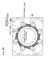
- Fig. 28 shows the attracting forces obtained through the dynamic magnetic field analysis on the same analytic conditions as those of the fourth embodiment of the present invention.
- the magnitudes of the vectors in the figure represent the magnitudes of the attracting forces.
- the attracting force of the electromagnet G on the entrance side of the magnetic pole is increased as compared with the electromagnet A (Fig. 32) by forming no rising interval.
- the reduction of the attracting force of the electromagnet G is compensated by forming no rising interval.
- the fifth embodiment of the present invention suppresses the occurrence of eddy current loss on the exit side (falling interval) of the magnetic pole where the magnetic flux density becomes dense by providing the magnetic flux density shape (taper shape) such that the magnetic flux density has a gentle slope.
- the fifth embodiment also provides the magnetic flux density shape such that the magnetic flux is increased by forming no taper shape on the entrance side of the magnetic pole where the magnetic flux density is sparse and the eddy current loss is small, thereby increasing the attracting force.
- the magnetic flux density varies with a gentle slope when one point of the rotor shifts from N to S or from S to N. That is, by providing the magnetic flux density distribution with the rising interval (approaching interval) and the falling interval (decelerating interval) like a cam curve and particularly prolonging the falling interval in which the eddy current loss is great, the occurrence of eddy current loss is suppressed to allow the substantial reduction in heat generation. Further, the formation of no slope in the rising interval in which the eddy current loss is small and the reduction of the gap between the magnetic pole and the rotor on the rising interval side increase the attracting force and increase the loading capability and the rigidity.
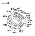
- FIG. 33 shows the principle of the NSSN type radial magnetic bearing electromagnet according to a sixth embodiment which is not an embodiment of the present invention.
- This stator section 402 is constructed of eight independent magnetic poles. That is, four north poles 403a through 403d and four south poles 404a through 404d are arranged in the circumferential direction with the homopolar combinations (NN or SS) arranged alternately.
- an inclined portion (taper portion) 405 formed at the end portion of the inner surface of the magnetic pole 403a, and perfect circle portions 406 and 407 arranged coaxially with the rotor 401.
- no taper is required to be formed in the homopolar (NN or SS) intervals and a taper is required to be formed only in the heteropolar (N and S) intervals since the magnetic flux density does not vary gently.
- mutually engageable projected and recessed connecting portions 408 and 409 for positioning and fastening the respective magnetic poles, winding accommodating portions 410 and 411, and slot portions 412 and 413 that are inter-heteropolar gaps. It is to be noted that the portions 405 through 411 are provided similarly for the other magnetic poles.
- pole division core method used for a motor is utilized for the stator of the magnetic bearing to which the fourth and fifth embodiments of the present invention is applied, then magnetic poles of special shapes having great face widths, i.e., small slot widths and inclined surfaces can be adopted.
- face width B 1 is set greater than the width B 2 of the winding portion in order to form the inclined surfaces 405 and 406 in sufficiently long intervals as shown in the enlarged view of Fig. 19, a winding process that has not been able to be performed in the conventional magnetic bearing electromagnet can be achieved by using the division method.
- each magnetic pole can be treated as a single unit, and therefore, a high-density winding can be provided fully in the space for accommodating the coil, also facilitating the laminating and assembling work. That is, by virtue of the permitted great face width of the electromagnet, the narrow portion for providing the inclined surface on the magnetic pole inner surface or the magnetic resistance with a distribution in the circumferential direction can be formed with a sufficient margin in sufficiently long intervals. As a result, rising and falling intervals having sufficient lengths can be provided, so that the substantial reduction of the loss can be achieved.
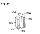
- Fig. 34 shows the shape of one magnetic pole 103a in the case where the aforementioned processing method is used for the fourth embodiment (Fig. 18).
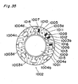
- Fig. 35 shows the principle of a radial magnetic bearing electromagnet (referred to as an electromagnet H) according to a seventh embodiment which is not an embodiment of the present invention.
- an electromagnet H a radial magnetic bearing electromagnet
- This stator section 1002 employs the NSSN type structure constructed of eight independent magnetic poles. That is, four north poles 1003a through 1003d and four south poles 1004a through 1004d are arranged in the circumferential direction with pairs of homopolar magnetic poles arranged adjacently.
- Fig. 36 shows a partially enlarged view of the magnetic pole 1003a.
- a rotor 81 and a stator section 82 This stator section 82 could also employ the NSSN type structure constructed of four north poles 83a through 83d and four south poles 84a through 84d, which are arranged in the circumferential direction with pairs of homopolar magnetic poles arranged adjacently.
- winding accommodating portions 85 and 86 the windings are not shown.
- slot portions 87 and 88 that are inter-heteropolar and inter-homopolar gaps, and their slot widths are equal to each other differently from the case of the electromagnet H.
- Electromagnet H Electromagnet F Loss(kW) 0.71 1.50
- the electromagnet H of the seventh embodiment of which the inter-homopolar gap S 2 of the magnetic poles is made sufficiently smaller than the inter-heteropolar gap S 1 of the magnetic poles has a substantially reduced loss as compared with the electromagnet F of the prior art example of which the inter-homopolar gap and the inter-heteropolar gap are equal to each other.
- the fundamental equation (equation 11) for obtaining the absolute value of the eddy current loss when an arbitrary periodic function is given to the magnetic flux density distribution is thus obtained from the aforementioned result, and calculation is performed by applying the equation to the seventh embodiment (electromagnet H of Fig. 35). Further, the effect of reducing the loss in the seventh embodiment is evaluated by comparison with the bearing structure (electromagnet F of Fig. 11) of which the gaps between the magnetic poles located on the left-hand side and the right-hand side are equal to each other.
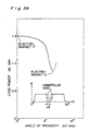
- Fig. 39 is the analytic results of the effect of reducing the eddy current loss of the electromagnet H of the seventh embodiment, obtained under the following conditions.
- Fig. 39 shows a graph of a relation between the eddy current loss and the above ⁇ deg.
- the seventh embodiment pays attention to the fact that the measure for reducing the loss differs depending on the following cases (1) and (2) with regard to one point of the rotor.
- the measure for suppressing the sudden change in magnetic flux density differs depending on the heteropolar side and the homopolar side. That is, the key factor of the seventh embodiment is that the electromagnets are arranged so that the shape of the single magnetic pole or the relative positional relation between adjacent magnetic poles has an asymmetrical arrangement between the heteropolar side and the homopolar side.
- the aforementioned seventh embodiment proposes the practical measures. Assuming that the gap to the magnetic pole end portion on the heteropolar side is S 1 and the gap on the homopolar side is S 2 , then S 2 is put closer to zero only on the homopolar side while maintaining the gap S 1 on the heteropolar side similar to the conventional bearing. If the heteropolar magnetic poles are put closer to each other (S 1 ⁇ 0), then the magnetic circuit does not passes through the rotor and a closed loop is formed between the magnetic poles. Consequently, the function as a magnetic bearing cannot be obtained. However, the method of putting the homopolar magnetic poles closer to each other exerts little influence on the basic performance of the magnetic bearing, and there is the effect of uniforming or flattening the magnetic flux density distribution as shown in Fig. 37. As a result, the eddy current loss due to the aforementioned reason (2) can be substantially reduced.
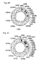
- Fig. 40 shows an eighth embodiment which is not an embodiment of the present invention, in which two homopolar magnetic poles are integrated with each other in an electromagnet of which the magnetic pole arrangement is the NSSN type.
- stator section 1052 employs the NSSN type structure constructed of eight magnetic poles. That is, the stator section 1052 is constructed of four north poles 1053a through 1053d and four south poles 1054a through 1054d, providing a construction in which homopolar magnetic pole pairs are arranged adjacently and arranged alternately in the circumferential direction. It is to be noted that each pair of homopolar magnetic poles (1053a and 1053b, for example) have an integrated structure.
- slot portions 1054 and 1055 located on the heteropolar side, mutually engageable projected and recessed connecting portions 1056 and 1057 for positioning and fastening the respective magnetic poles, and winding accommodating portions 1058 through 1061.
- the reference numerals 1062 and 1063 denote a boundary portion A and a boundary portion B, respectively.
- the boundary portion A which is normally separated, is integrated, and therefore, the magnetic flux density distribution can be further flattened for the reduction of loss.
- the boundary portion B is also integrated, and therefore, the magnetic poles 1053a and 1053b can be treated as a single component in the assembling stage. Therefore, according to the electromagnet of the eighth embodiment, the pole division method capable of providing the high-density winding can be applied.
- Fig. 41 shows a ninth embodiment, which is intended for substantially reducing the eddy current loss due to the aforementioned factor (1) in the case where the present invention is applied to an electromagnet of which the magnetic pole arrangement is the NSSN type. That is, there is shown the case where a measure for suppressing the sudden change in magnetic flux density is effected by forming a gently inclined portion (rising and falling intervals of the magnetic flux density curve) on the inner surface of the magnetic poles on the heteropolar side.
- This stator section 1072 employs the NSSN type structure constructed of eight independent magnetic poles. That is, four north poles 1073a through 1073d and four south poles 1074a through 1074d are arranged in the circumferential direction with homopolar magnetic pole pairs arranged adjacently and arranged alternately in the circumferential direction.
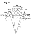
- inclined portions 1075 and 1076 formed at both end portions of the inner surfaces of the magnetic poles 1073a and 1073b, perfect circle portions 1077 and 1078, slot portions 1079 and 1080 located on the heteropolar side, mutually engageable projected and recessed connecting portions 1081 through 1083 for positioning and fastening the respective magnetic poles, winding accommodating portions 1084 through 1087, and a slot portion 1088 located on the homopolar side.
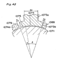
- Fig. 42 shows an enlarged view of part of the magnetic pole 1073a.
- a gently inclined surface is formed on the magnetic pole inner surface in the interval ⁇ extending from the magnetic pole end portion on the heteropolar side to the coaxial portion, while the shape of the magnetic pole inner surface is formed coaxially with the axial center of the rotor similar to the conventional arrangement in the interval ⁇ extending from the magnetic pole end portion on the homopolar side to the coaxial portion.
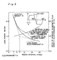
- Fig. 43 shows the analytic result of the loss power in the rising interval ⁇ with S 1 and S 2 kept constant. The results are summarized as follows.
- the eddy current loss can be reduced to a value slightly smaller than one half while maintaining the same loading capability and rigidity.
- the magnetic flux density varies with a gentle slope when one point of the rotor shifts from N to S or from S to N. That is, by providing the magnetic flux density distribution with a sufficiently long rising interval (approaching interval) and a sufficiently long falling interval (decelerating interval) like a cam curve, the generation of eddy current loss is suppressed to allow the substantial reduction in heat generation.
- the provision of the magnetic flux density distribution with the rising interval is not just for the effect of reducing the loss.
- the loading capability and rigidity of the magnetic bearing are determined by the total area of the magnetic flux density distribution, and therefore, the ninth embodiment of which the magnetic flux density distribution has a close resemblance to the trapezoidal wave is advantageous since the ninth embodiment can provide a large total area as compared with the conventional magnetic bearing (Fig. 38, the magnetic flux density distribution being not shown) of which the magnetic flux density distribution has a close resemblance to the rectangular wave.
- the ninth embodiment there is used the method of forming the inclined surfaces only on the heteropolar side of the magnetic poles and putting the magnetic poles close to each other on the homopolar side similar to the seventh embodiment. According to the method of putting the homopolar magnetic poles close to each other is advantageous in terms of the loading capability and rigidity for the reason that the magnetic flux density distribution is allowed to have a great total area.
- the loss can also be reduced by forming inclined surfaces on the homopolar side instead of the method of putting the magnetic poles close to each other.
- the rate of change in the magnetic flux density on the homopolar side is not so great in contrast to that on the heteropolar side, and therefore, the angle of the inclined surface to be formed is allowed to be sufficiently small. That is, assuming that the angle of the inclined surface to be formed on the heteropolar side is ⁇ 1 and the angle of the inclined surface to be formed on the homopolar side is ⁇ 2 , then it is proper to provide the construction in which ⁇ 1 > ⁇ 2 as shown in Fig. 45.
- the above ninth embodiment is constructed so that the magnetic flux density distribution is provided with the rising characteristic by forming the inclined surface on the inner surface of the magnetic pole and varying the gap (air gap) between the magnetic pole and the rotor in the circumferential direction.
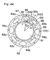
- Fig. 44 shows a tenth embodiment, in which the magnetic flux density distribution is provided with a long-interval rising characteristic by forming a portion of which the width (area) of the magnetic path is reduced along the path that extends from the winding portion to the magnetic pole end portion in, for example, the magnetic circuit formed through north pole ⁇ air gap ⁇ rotor ⁇ air gap ⁇ south pole. Therefore, according to the tenth embodiment, the magnetic pole is allowed to have an inner surface shape coaxial with the rotor.
- stator section 92 is provided by the NSNS type structure constructed of eight independent magnetic poles. That is, the stator section 92 is constructed of four north poles 93a through 93d and four south poles 94a through 94d, which are alternately arranged in the circumferential direction. In this case, with regard to one north pole 93a, there are formed constricted portions, i.e., very narrow portions 95 and 96 that have a reduced width in the circumferential direction of the magnetic path are formed between the magnetic pole inner surface on the rotor side and a winding accommodating portion 97.
- constricted portions i.e., very narrow portions 95 and 96 that have a reduced width in the circumferential direction of the magnetic path are formed between the magnetic pole inner surface on the rotor side and a winding accommodating portion 97.
- a slot portion 97 located on the heteropolar side a slot portion 98 located on the homopolar side, mutually engageable projected and recessed connecting portions 99, 100, and 2101 for positioning and fastening the respective magnetic poles and winding accommodating portions 2102 and 2103 (the windings are not shown).
- Fig. 44 there is formed a magnetic pole of a portion of which the magnetic path width is reduced from d 1 to d 2 in an interval of the angle ⁇ through the path that extends from a point "a" at which a winding is provided around the point to an end portion "b" of the magnetic pole.
- the width of the magnetic path is sufficiently large so that the path is effective for conducting the magnetic flux.
- the magnetic flux density distribution formed between the magnetic pole inner surface and the rotor 91 is not uniformed in the circumferential direction but formed into a pseudo trapezoidal wave having an angle of inclination.
- the magnetic flux density distribution it is acceptable to provide the magnetic flux density distribution by devising the shape of the magnetic path other than the portion of the magnetic pole that faces the rotor, e.g., by forming the constricted portion (very narrow portion) in the magnetic path as described in connection with the tenth embodiment.
- the radial electromagnet is normally constructed of a plurality of magnetic poles, and it is preferable to keep the thermal deformation of the spindle symmetrical about its axis by uniforming the loss (i.e., the calorific value) of the magnetic poles in order to ensure a high accuracy.
- pole division core method used for a motor is utilized for the stator of a magnetic bearing to which the tenth embodiment of the present invention is applied, then magnetic poles of special shapes each having a great face width, i.e., a small slot width and an inclined surface can be adopted.
- a winding process that has not been able to be performed in the conventional magnetic bearing electromagnet can be achieved by using the division method.
- each magnetic pole can be treated as a single unit, and therefore, a high-density winding can be provided fully in the space for accommodating the coil, also facilitating the laminating and assembling work.
- the constricted portion (indicated by the reference numeral 95 in Fig. 44) for providing the inclined surface on the magnetic pole inner surface or the magnetic resistance with a distribution in the circumferential direction can be formed in sufficiently long intervals with a sufficient margin.
- rising and falling intervals each having a sufficient length can be provided, so that the substantial reduction of the loss can be achieved.
- the heat generation due to the eddy current loss occurring at the rotor of the magnetic bearing can be substantially reduced with the simple construction not much changed from that of the conventional magnetic bearing.
- the temperature rise of the main shaft can be suppressed. Therefore, the reliability of the spindle constructed of a plurality of composite components can be improved and the axial expansion of the main shaft can be suppressed, so that a high runout accuracy can be ensured.
- the present invention provides a very effective means for achieving a high DN value (main shaft diameter ⁇ number of revolutions) of the magnetic bearing spindle.
- the issues of the conventional magnetic bearing during high-speed rotation are solved. Therefore, the magnetic bearing can cope with the requirement for the high-speed cutting while further utilizing the fundamental capabilities (high speed and high rigidity) inherently owned by the magnetic bearing spindle, providing a very great practical effect.
Landscapes
- Engineering & Computer Science (AREA)
- General Engineering & Computer Science (AREA)
- Mechanical Engineering (AREA)
- Physics & Mathematics (AREA)
- Electromagnetism (AREA)
- Magnetic Bearings And Hydrostatic Bearings (AREA)
Claims (2)
- Ein radiales Magnetlager enthaltend:einen drehbaren Rotor; undeinen stationären Stator mit mehreren in Umfangsrichtung um den Stator angeordneten magnetischen Nordpolen und mehreren in Umfangsrichtung um den Stator angeordneten magnetischen Südpolen, wobei jeder der Magnetpole einen Umfangswinkel ψ in Bezug auf ein Zentrum des Magnetlagers umfasst, der drehbare Rotor innerhalb des Stators derart angeordnet ist, dass eine äußere Oberfläche des drehbaren Rotors einer inneren Oberfläche eines jeden Magnetpols gegenüber liegt, jeder der Magnetpole in einer solchen Gestalt ausgebildet ist, dass er einen flusssteigernden Abschnitt an einem Ende von jedem der Magnetpole in Bezug auf die Umfangsrichtung des Stators aufweist, der flusssteigernde Abschnitt einen Umfangswinkel α in Bezug auf das Zentrum des Magnetlagers umfasst, wobei ein magnetischer Fluss zwischen dem drehbaren Rotor und der inneren Oberfläche eines jeden der magnetischen Pole an dem flusssteigernden Abschnitt eine graduell wachsende Dichteverteilung von dem Ende eines jeden Magnetpols zu einem Zentrum von einem jeden der Magnetpole in Bezug auf die Umfangsrichtung des Stators aufweist, und wobei das Verhältnis α/ψ größer als 0,15 ist.
- Das Magnetlager nach Anspruch 1, wobei die innere Oberfläche eines jeden Magnetpols einen schrägen Teil und einen runden Teil aufweist und mit der äußeren Oberfläche des drehbaren Rotors koaxial so angeordnet ist, dass eine im magnetischen Weg zwischen der inneren Oberfläche eines Magnetpols und der äußeren Oberfläche des Rotors gebildete Lücke von dem Ende des Magnetpols zum Zentrum des Magnetpols in der Umfangsrichtung schmaler und eine einheitliche Lücke im magnetischen Weg zwischen dem runden Teil und dem drehbaren Rotor aufrechterhalten wird.
Applications Claiming Priority (4)
| Application Number | Priority Date | Filing Date | Title |
|---|---|---|---|
| JP11831998 | 1998-04-28 | ||
| JP11831998A JP3882334B2 (ja) | 1998-04-28 | 1998-04-28 | 磁気軸受装置 |
| JP15429398A JP3708331B2 (ja) | 1998-06-03 | 1998-06-03 | 磁気軸受装置 |
| JP15429398 | 1998-06-03 |
Publications (3)
| Publication Number | Publication Date |
|---|---|
| EP0953781A2 EP0953781A2 (de) | 1999-11-03 |
| EP0953781A3 EP0953781A3 (de) | 2000-08-09 |
| EP0953781B1 true EP0953781B1 (de) | 2005-04-06 |
Family
ID=26456274
Family Applications (1)
| Application Number | Title | Priority Date | Filing Date |
|---|---|---|---|
| EP99108299A Expired - Lifetime EP0953781B1 (de) | 1998-04-28 | 1999-04-28 | Magnetlager |
Country Status (3)
| Country | Link |
|---|---|
| US (1) | US6194800B1 (de) |
| EP (1) | EP0953781B1 (de) |
| DE (1) | DE69924556D1 (de) |
Families Citing this family (29)
| Publication number | Priority date | Publication date | Assignee | Title |
|---|---|---|---|---|
| US6940205B1 (en) * | 1997-09-08 | 2005-09-06 | Matsushita Electric Industrial Co., Ltd. | Permanent magnet synchronous motor |
| JP3609649B2 (ja) * | 1999-06-29 | 2005-01-12 | 三洋電機株式会社 | ブラシレスdcモータ及びこのモータを用いた冷媒圧縮機 |
| JP2001078389A (ja) * | 1999-09-01 | 2001-03-23 | Sankyo Seiki Mfg Co Ltd | 磁気浮上型電動機 |
| JP3383251B2 (ja) * | 1999-12-27 | 2003-03-04 | 三菱電機株式会社 | 車両用交流発電機の固定子 |
| JP3740984B2 (ja) * | 2000-02-10 | 2006-02-01 | 日産自動車株式会社 | 電動機の磁極位置検出装置 |
| JP2003021140A (ja) * | 2001-07-06 | 2003-01-24 | Sankyo Seiki Mfg Co Ltd | 制御型ラジアル磁気軸受 |
| JP2003254285A (ja) * | 2002-02-28 | 2003-09-10 | Boc Edwards Technologies Ltd | ポンプ装置 |
| US6982532B2 (en) * | 2003-12-08 | 2006-01-03 | A. O. Smith Corporation | Electric machine |
| WO2006123659A1 (ja) * | 2005-05-17 | 2006-11-23 | Denso Corporation | モータとその制御装置 |
| US7471022B2 (en) * | 2006-09-22 | 2008-12-30 | Sortore Christopher K | Magnetic bearing |
| RU2010142965A (ru) * | 2008-04-17 | 2012-05-27 | Синкрони, Инк. (US) | Высокоскоростной электродвигатель с постоянным магнитом и генератор с металлическим ротором с низким уровнем потерь |
| CA2721818A1 (en) * | 2008-04-18 | 2009-11-19 | Synchrony, Inc. | Magnetic thrust bearing with integrated electronics |
| JP5273526B2 (ja) * | 2008-06-27 | 2013-08-28 | 株式会社Ihi | 磁気軸受装置 |
| US9583991B2 (en) * | 2009-06-24 | 2017-02-28 | Synchrony, Inc. | Systems, devices, and/or methods for managing magnetic bearings |
| US8987959B2 (en) | 2010-06-23 | 2015-03-24 | Dresser-Rand Company | Split magnetic thrust bearing |
| DE102010044713A1 (de) * | 2010-09-08 | 2012-03-08 | Minebea Co., Ltd. | Bürstenloser Gleichstrommotor |
| US20130038162A1 (en) * | 2011-08-11 | 2013-02-14 | Zhongshan Broad-Ocean Motor Manufacturing Co., Ltd | Motor |
| US10374471B2 (en) | 2012-07-27 | 2019-08-06 | Regal Beloit America, Inc. | Methods, systems, and apparatus for reducing cogging torque in an electric machine |
| JP5700033B2 (ja) * | 2012-09-12 | 2015-04-15 | ダイキン工業株式会社 | 磁気軸受 |
| US9621013B2 (en) * | 2013-03-15 | 2017-04-11 | Ingersoll-Rand Company | Rotating machine with magnetic bearing |
| DE102015207341B4 (de) * | 2015-04-22 | 2019-02-14 | Ford Global Technologies, Llc | Verdichter und Kraftfahrzeug |
| CN108696086B (zh) * | 2018-07-13 | 2023-12-29 | 江苏独角客电机科技有限公司 | 一种径向磁通电机 |
| CN112688442B (zh) * | 2020-12-31 | 2021-08-24 | 湖南科技大学 | 交流牵引电机定子齿肩削角降噪优化设计方法 |
| EP4064555B1 (de) | 2021-03-25 | 2025-08-06 | Wobben Properties GmbH | Windenergieanlage und verfahren zum steuern einer windenergieanlage |
| CN117477809A (zh) * | 2022-07-20 | 2024-01-30 | 湖北美的洗衣机有限公司 | 定子和电机 |
| CN115507119B (zh) * | 2022-10-14 | 2026-03-20 | 珠海格力电器股份有限公司 | 一种磁悬浮主动式三自由度轴承、电机和压缩机 |
| DE102022213675A1 (de) * | 2022-12-14 | 2024-06-20 | Deutsches Zentrum für Luft- und Raumfahrt e.V. | Aktives Magnetlager mit reduzierter Verlustleistung |
| CN116753826A (zh) * | 2023-06-28 | 2023-09-15 | 江苏永续动力科技有限公司 | 一种轴—径向一体化传感器结构 |
| AU2024339929A1 (en) * | 2023-09-14 | 2026-03-26 | Cláudio Henrique Teixeira RIBEIRO | Magnetic separators for increased residencey of material feeds, and methods of using the same |
Citations (2)
| Publication number | Priority date | Publication date | Assignee | Title |
|---|---|---|---|---|
| US4504098A (en) * | 1982-11-16 | 1985-03-12 | Societe Europeenne De Propulsion | Electromagnetic bearing for high temperature environment |
| US5319273A (en) * | 1992-10-26 | 1994-06-07 | Satcon Technology Corporation | Fixed gain electromagnetic actuator and electromagnetic bearing incorporating same |
Family Cites Families (9)
| Publication number | Priority date | Publication date | Assignee | Title |
|---|---|---|---|---|
| JPS60164013A (ja) * | 1984-02-03 | 1985-08-27 | Toshiba Corp | 磁気軸受 |
| JPS61180019A (ja) | 1985-01-28 | 1986-08-12 | Yaskawa Electric Mfg Co Ltd | 磁気軸受 |
| DE3700774C2 (de) * | 1986-01-13 | 1998-11-12 | Papst Motoren Gmbh & Co Kg | Kollektorlose Gleichstrommaschine |
| US5563565A (en) * | 1993-11-23 | 1996-10-08 | University Of Chicago | Method for obtaining large levitation pressure in superconducting magnetic bearings |
| US5682072A (en) * | 1994-01-20 | 1997-10-28 | Nsk Ltd. | Three-phase brushless motor |
| US5698917A (en) * | 1995-09-25 | 1997-12-16 | Glacier Rpb Inc. | Electromagnetic bearing with a stationary armature canning arrangement |
| US5864303A (en) * | 1996-06-14 | 1999-01-26 | Rosen Motors L.P. | Capacitive sensor system for magnetic bearings |
| US5929548A (en) * | 1997-09-08 | 1999-07-27 | Active Power, Inc. | High inertia inductor-alternator |
| US5962940A (en) * | 1998-01-21 | 1999-10-05 | Imlach; Joseph | High specific load capacity radial magnetic bearing actuator |
-
1999
- 1999-04-28 EP EP99108299A patent/EP0953781B1/de not_active Expired - Lifetime
- 1999-04-28 US US09/301,476 patent/US6194800B1/en not_active Expired - Fee Related
- 1999-04-28 DE DE69924556T patent/DE69924556D1/de not_active Expired - Fee Related
Patent Citations (2)
| Publication number | Priority date | Publication date | Assignee | Title |
|---|---|---|---|---|
| US4504098A (en) * | 1982-11-16 | 1985-03-12 | Societe Europeenne De Propulsion | Electromagnetic bearing for high temperature environment |
| US5319273A (en) * | 1992-10-26 | 1994-06-07 | Satcon Technology Corporation | Fixed gain electromagnetic actuator and electromagnetic bearing incorporating same |
Also Published As
| Publication number | Publication date |
|---|---|
| EP0953781A2 (de) | 1999-11-03 |
| EP0953781A3 (de) | 2000-08-09 |
| DE69924556D1 (de) | 2005-05-12 |
| US6194800B1 (en) | 2001-02-27 |
Similar Documents
| Publication | Publication Date | Title |
|---|---|---|
| EP0953781A2 (de) | Magnetlager | |
| EP3635848B1 (de) | Vorgebogene rotoren zur steuerung des magnet-stator-spaltes bei axialflussmaschinen | |
| EP1684400B1 (de) | Rotierende elektrische Maschine | |
| JP5288698B2 (ja) | 永久磁石式リラクタンス型回転電機 | |
| EP1158651B1 (de) | Permanentmagnetischer Reluktanzmotor | |
| US6635976B2 (en) | Magnetic levitation motor and method for manufacturing the same | |
| US20040135450A1 (en) | Magnetic levitation motor | |
| US5747913A (en) | Rotor for hybrid generator having improved magnet retention | |
| US20030197440A1 (en) | Stator core for a magnetic bearing and the method of manufacturing it | |
| EP1115194A2 (de) | Magnetschwebemotor and sein Herstellungsverfahren | |
| EP1857695B1 (de) | Kugellager | |
| JP2002247823A (ja) | 磁気浮上型電動機 | |
| JP3708331B2 (ja) | 磁気軸受装置 | |
| JPH10150755A (ja) | 半径方向力発生装置、巻線付き回転機、および回転装置 | |
| JP3712565B2 (ja) | 回転装置及び当該回転装置を備えた加工装置 | |
| JP2000018246A (ja) | 回転装置 | |
| JP3793863B2 (ja) | 磁気軸受のステータユニットの製造方法 | |
| JP3882334B2 (ja) | 磁気軸受装置 | |
| JP4792793B2 (ja) | ダイレクトドライブモータ | |
| EP1072803A2 (de) | Magnetische Lagervorrichtung | |
| JP2000283158A (ja) | ラジアル磁気軸受 | |
| US12316172B2 (en) | Rotor for an electric ring machine, corresponding ring machine and method for producing a rotor | |
| JPH11266564A (ja) | 磁気軸受スピンドル | |
| JP2004316756A (ja) | 5軸制御磁気軸受 | |
| AU2020382759A1 (en) | Improved rotor assemblies for axial flux machines |
Legal Events
| Date | Code | Title | Description |
|---|---|---|---|
| PUAI | Public reference made under article 153(3) epc to a published international application that has entered the european phase |
Free format text: ORIGINAL CODE: 0009012 |
|
| AK | Designated contracting states |
Kind code of ref document: A2 Designated state(s): DE FR |
|
| AX | Request for extension of the european patent |
Free format text: AL;LT;LV;MK;RO;SI |
|
| PUAL | Search report despatched |
Free format text: ORIGINAL CODE: 0009013 |
|
| AK | Designated contracting states |
Kind code of ref document: A3 Designated state(s): AT BE CH CY DE DK ES FI FR GB GR IE IT LI LU MC NL PT SE |
|
| AX | Request for extension of the european patent |
Free format text: AL;LT;LV;MK;RO;SI |
|
| RIC1 | Information provided on ipc code assigned before grant |
Free format text: 7F 16C 32/04 A, 7F 16C 39/06 B |
|
| 17P | Request for examination filed |
Effective date: 20010209 |
|
| AKX | Designation fees paid |
Free format text: DE FR |
|
| 17Q | First examination report despatched |
Effective date: 20030717 |
|
| GRAP | Despatch of communication of intention to grant a patent |
Free format text: ORIGINAL CODE: EPIDOSNIGR1 |
|
| GRAS | Grant fee paid |
Free format text: ORIGINAL CODE: EPIDOSNIGR3 |
|
| GRAA | (expected) grant |
Free format text: ORIGINAL CODE: 0009210 |
|
| AK | Designated contracting states |
Kind code of ref document: B1 Designated state(s): DE FR |
|
| REF | Corresponds to: |
Ref document number: 69924556 Country of ref document: DE Date of ref document: 20050512 Kind code of ref document: P |
|
| PG25 | Lapsed in a contracting state [announced via postgrant information from national office to epo] |
Ref country code: DE Free format text: LAPSE BECAUSE OF NON-PAYMENT OF DUE FEES Effective date: 20051101 |
|
| PLBE | No opposition filed within time limit |
Free format text: ORIGINAL CODE: 0009261 |
|
| STAA | Information on the status of an ep patent application or granted ep patent |
Free format text: STATUS: NO OPPOSITION FILED WITHIN TIME LIMIT |
|
| ET | Fr: translation filed | ||
| 26N | No opposition filed |
Effective date: 20060110 |
|
| PGFP | Annual fee paid to national office [announced via postgrant information from national office to epo] |
Ref country code: FR Payment date: 20100521 Year of fee payment: 12 |
|
| REG | Reference to a national code |
Ref country code: FR Ref legal event code: ST Effective date: 20111230 |
|
| PG25 | Lapsed in a contracting state [announced via postgrant information from national office to epo] |
Ref country code: FR Free format text: LAPSE BECAUSE OF NON-PAYMENT OF DUE FEES Effective date: 20110502 |