EP0953881A1 - Cartouche de traitement et appareil électrophotographique - Google Patents
Cartouche de traitement et appareil électrophotographique Download PDFInfo
- Publication number
- EP0953881A1 EP0953881A1 EP99108432A EP99108432A EP0953881A1 EP 0953881 A1 EP0953881 A1 EP 0953881A1 EP 99108432 A EP99108432 A EP 99108432A EP 99108432 A EP99108432 A EP 99108432A EP 0953881 A1 EP0953881 A1 EP 0953881A1
- Authority
- EP
- European Patent Office
- Prior art keywords
- resin
- photosensitive member
- substituted
- group
- electrophotographic photosensitive
- Prior art date
- Legal status (The legal status is an assumption and is not a legal conclusion. Google has not performed a legal analysis and makes no representation as to the accuracy of the status listed.)
- Granted
Links
Images

Classifications
-
- G—PHYSICS
- G03—PHOTOGRAPHY; CINEMATOGRAPHY; ANALOGOUS TECHNIQUES USING WAVES OTHER THAN OPTICAL WAVES; ELECTROGRAPHY; HOLOGRAPHY
- G03G—ELECTROGRAPHY; ELECTROPHOTOGRAPHY; MAGNETOGRAPHY
- G03G5/00—Recording-members for original recording by exposure, e.g. to light, to heat or to electrons; Manufacture thereof; Selection of materials therefor
-
- G—PHYSICS
- G03—PHOTOGRAPHY; CINEMATOGRAPHY; ANALOGOUS TECHNIQUES USING WAVES OTHER THAN OPTICAL WAVES; ELECTROGRAPHY; HOLOGRAPHY
- G03G—ELECTROGRAPHY; ELECTROPHOTOGRAPHY; MAGNETOGRAPHY
- G03G5/00—Recording-members for original recording by exposure, e.g. to light, to heat or to electrons; Manufacture thereof; Selection of materials therefor
- G03G5/14—Inert intermediate or cover layers for charge-receiving layers
- G03G5/147—Cover layers
- G03G5/14708—Cover layers comprising organic material
-
- G—PHYSICS
- G03—PHOTOGRAPHY; CINEMATOGRAPHY; ANALOGOUS TECHNIQUES USING WAVES OTHER THAN OPTICAL WAVES; ELECTROGRAPHY; HOLOGRAPHY
- G03G—ELECTROGRAPHY; ELECTROPHOTOGRAPHY; MAGNETOGRAPHY
- G03G5/00—Recording-members for original recording by exposure, e.g. to light, to heat or to electrons; Manufacture thereof; Selection of materials therefor
- G03G5/02—Charge-receiving layers
- G03G5/04—Photoconductive layers; Charge-generation layers or charge-transporting layers; Additives therefor; Binders therefor
- G03G5/05—Organic bonding materials; Methods for coating a substrate with a photoconductive layer; Inert supplements for use in photoconductive layers
- G03G5/0503—Inert supplements
-
- G—PHYSICS
- G03—PHOTOGRAPHY; CINEMATOGRAPHY; ANALOGOUS TECHNIQUES USING WAVES OTHER THAN OPTICAL WAVES; ELECTROGRAPHY; HOLOGRAPHY
- G03G—ELECTROGRAPHY; ELECTROPHOTOGRAPHY; MAGNETOGRAPHY
- G03G5/00—Recording-members for original recording by exposure, e.g. to light, to heat or to electrons; Manufacture thereof; Selection of materials therefor
- G03G5/02—Charge-receiving layers
- G03G5/04—Photoconductive layers; Charge-generation layers or charge-transporting layers; Additives therefor; Binders therefor
- G03G5/05—Organic bonding materials; Methods for coating a substrate with a photoconductive layer; Inert supplements for use in photoconductive layers
- G03G5/0528—Macromolecular bonding materials
- G03G5/0532—Macromolecular bonding materials obtained by reactions only involving carbon-to-carbon unsatured bonds
- G03G5/0539—Halogenated polymers
-
- G—PHYSICS
- G03—PHOTOGRAPHY; CINEMATOGRAPHY; ANALOGOUS TECHNIQUES USING WAVES OTHER THAN OPTICAL WAVES; ELECTROGRAPHY; HOLOGRAPHY
- G03G—ELECTROGRAPHY; ELECTROPHOTOGRAPHY; MAGNETOGRAPHY
- G03G5/00—Recording-members for original recording by exposure, e.g. to light, to heat or to electrons; Manufacture thereof; Selection of materials therefor
- G03G5/02—Charge-receiving layers
- G03G5/04—Photoconductive layers; Charge-generation layers or charge-transporting layers; Additives therefor; Binders therefor
- G03G5/05—Organic bonding materials; Methods for coating a substrate with a photoconductive layer; Inert supplements for use in photoconductive layers
- G03G5/0528—Macromolecular bonding materials
- G03G5/0557—Macromolecular bonding materials obtained otherwise than by reactions only involving carbon-to-carbon unsatured bonds
- G03G5/056—Polyesters
-
- G—PHYSICS
- G03—PHOTOGRAPHY; CINEMATOGRAPHY; ANALOGOUS TECHNIQUES USING WAVES OTHER THAN OPTICAL WAVES; ELECTROGRAPHY; HOLOGRAPHY
- G03G—ELECTROGRAPHY; ELECTROPHOTOGRAPHY; MAGNETOGRAPHY
- G03G5/00—Recording-members for original recording by exposure, e.g. to light, to heat or to electrons; Manufacture thereof; Selection of materials therefor
- G03G5/02—Charge-receiving layers
- G03G5/04—Photoconductive layers; Charge-generation layers or charge-transporting layers; Additives therefor; Binders therefor
- G03G5/05—Organic bonding materials; Methods for coating a substrate with a photoconductive layer; Inert supplements for use in photoconductive layers
- G03G5/0528—Macromolecular bonding materials
- G03G5/0557—Macromolecular bonding materials obtained otherwise than by reactions only involving carbon-to-carbon unsatured bonds
- G03G5/0564—Polycarbonates
-
- G—PHYSICS
- G03—PHOTOGRAPHY; CINEMATOGRAPHY; ANALOGOUS TECHNIQUES USING WAVES OTHER THAN OPTICAL WAVES; ELECTROGRAPHY; HOLOGRAPHY
- G03G—ELECTROGRAPHY; ELECTROPHOTOGRAPHY; MAGNETOGRAPHY
- G03G5/00—Recording-members for original recording by exposure, e.g. to light, to heat or to electrons; Manufacture thereof; Selection of materials therefor
- G03G5/02—Charge-receiving layers
- G03G5/04—Photoconductive layers; Charge-generation layers or charge-transporting layers; Additives therefor; Binders therefor
- G03G5/05—Organic bonding materials; Methods for coating a substrate with a photoconductive layer; Inert supplements for use in photoconductive layers
- G03G5/0528—Macromolecular bonding materials
- G03G5/0557—Macromolecular bonding materials obtained otherwise than by reactions only involving carbon-to-carbon unsatured bonds
- G03G5/0582—Polycondensates comprising sulfur atoms in the main chain
-
- G—PHYSICS
- G03—PHOTOGRAPHY; CINEMATOGRAPHY; ANALOGOUS TECHNIQUES USING WAVES OTHER THAN OPTICAL WAVES; ELECTROGRAPHY; HOLOGRAPHY
- G03G—ELECTROGRAPHY; ELECTROPHOTOGRAPHY; MAGNETOGRAPHY
- G03G5/00—Recording-members for original recording by exposure, e.g. to light, to heat or to electrons; Manufacture thereof; Selection of materials therefor
- G03G5/14—Inert intermediate or cover layers for charge-receiving layers
- G03G5/147—Cover layers
- G03G5/14708—Cover layers comprising organic material
- G03G5/14713—Macromolecular material
- G03G5/14747—Macromolecular material obtained otherwise than by reactions only involving carbon-to-carbon unsaturated bonds
- G03G5/14752—Polyesters
-
- G—PHYSICS
- G03—PHOTOGRAPHY; CINEMATOGRAPHY; ANALOGOUS TECHNIQUES USING WAVES OTHER THAN OPTICAL WAVES; ELECTROGRAPHY; HOLOGRAPHY
- G03G—ELECTROGRAPHY; ELECTROPHOTOGRAPHY; MAGNETOGRAPHY
- G03G5/00—Recording-members for original recording by exposure, e.g. to light, to heat or to electrons; Manufacture thereof; Selection of materials therefor
- G03G5/14—Inert intermediate or cover layers for charge-receiving layers
- G03G5/147—Cover layers
- G03G5/14708—Cover layers comprising organic material
- G03G5/14713—Macromolecular material
- G03G5/14747—Macromolecular material obtained otherwise than by reactions only involving carbon-to-carbon unsaturated bonds
- G03G5/14756—Polycarbonates
-
- G—PHYSICS
- G03—PHOTOGRAPHY; CINEMATOGRAPHY; ANALOGOUS TECHNIQUES USING WAVES OTHER THAN OPTICAL WAVES; ELECTROGRAPHY; HOLOGRAPHY
- G03G—ELECTROGRAPHY; ELECTROPHOTOGRAPHY; MAGNETOGRAPHY
- G03G5/00—Recording-members for original recording by exposure, e.g. to light, to heat or to electrons; Manufacture thereof; Selection of materials therefor
- G03G5/14—Inert intermediate or cover layers for charge-receiving layers
- G03G5/147—Cover layers
- G03G5/14708—Cover layers comprising organic material
- G03G5/14713—Macromolecular material
- G03G5/14747—Macromolecular material obtained otherwise than by reactions only involving carbon-to-carbon unsaturated bonds
- G03G5/14778—Polycondensates comprising sulfur atoms in the main chain
Definitions
- This invention relates to a process cartridge and an electrophotographic apparatus which have a charging means and an electrophotographic photosensitive member. More particularly, it relates to a process cartridge and an electrophotographic apparatus which have a specific charging member and an electrophotographic photosensitive member having a surface layer containing a specific resin and fluorine-containing resin particles.
- U.S. Patent No. 3,837,851 discloses a photosensitive member having a charge transport layer containing triarylpyrazoline
- U.S. Patent No. 3,871,880 discloses a photosensitive member comprising a charge generation layer and a charge transport layer, the former containing a derivative of a perylene pigment and the latter being formed of a condensation product of 3-propylene with formaldehyde.
- the organic photoconductive compounds have their own different wavelength regions where they are sensitive.
- Japanese Patent Applications Laid-open No. 61-272754 and No. 56-167759 disclose compounds having a high sensitivity at the visible region
- Japanese Patent Applications Laid-open No. 57-19567 and No. 61-228453 disclose compounds having a sensitivity at the infrared region.
- those having a sensitivity at the infrared region are used in laser beam printers (hereinafter "LBP") and LED printers, and the demand for them and its frequency are increasing.
- LBP laser beam printers
- LED printers LED printers
- Japanese Patent Applications Laid-open No. 57-17826 and No. 58-40566 disclose a contact charging means which charges an electrophotographic photosensitive member electrostatically by applying a voltage to a charging member provided in contact with the electrophotographic photosensitive member.
- the contact charging means have advantages that it may cause ozone in a greatly smaller quantity than corona charging means, and the contact charging means is very economical because it does not waste the electric currents the corona charging means may waste by about 80% as currents flowing to a shield among those flowing to a charging assembly.
- the contact charging means since in the contact charging means the contact charging member comes into contact with the electrophotographic photosensitive member, the electrophotographic photosensitive member is required to have a superior mechanical strength.
- applied voltage a voltage formed by superimposing an AC voltage on a DC voltage
- the scrape (amount of scrape) of the electrophotographic photosensitive member may increase to cause fog on images, bringing about an additional problem.
- This phenomenon may especially remarkably occur when the contact charging means is used which employ a voltage formed by superimposing an AC voltage on a DC voltage, and may more remarkably occur when fully moistened paper is used as a transfer medium.
- Japanese Patent Application Laid-open No. 62-160458 discloses using both a low-molecular weight polycarbonate resin and a high-molecular weight polycarbonate resin so that a surface layer having deteriorated, of the electrophotographic photosensitive member can be removed together with deposits.
- Such a means can not be well effective because the electrophotographic photosensitive member may especially remarkably come to have a larger surface roughness with its use when the above specific contact charging means is employed.
- An object of the present invention is to provide a process cartridge and an electrophotographic apparatus which have an electrophotographic photosensitive member having a superior running performance and also hardly causing smeared images and an increase in light-area potential.
- the present invention provides a process cartridge comprising;
- the present invention also provides an electrophotographic apparatus comprising;
- the process cartridge and electrophotographic apparatus of the present invention have a charging means making use of a voltage formed by superimposing an alternating-current (AC) voltage on a direct-current (DC) voltage, and an electrophotographic photosensitive member having a surface layer which contains i) at least one of a polyarylate resin having a weight-average molecular weight of from 7.5 ⁇ 10 3 to 3.7 ⁇ 10 4 and having a structural unit represented by the following Formula (1) and a polycarbonate resin having a weight-average molecular weight of from 7.5 ⁇ 10 3 to 3.7 ⁇ 10 4 and having a structural unit represented by the following Formula (2), and ii) fluorine-containing resin particles.
- AC alternating-current
- DC direct-current
- X 1 represents -CR 13 R 14 - (where R 13 and R 14 are the same or different and each represent a hydrogen atom, a trifluoromethyl group, a substituted or unsubstituted alkyl group or a substituted or unsubstituted aryl group), a substituted or unsubstituted cycloalkylidene group, a substituted or unsubstituted ⁇ , ⁇ -alkylene group, a single bond, -O-, -S-, -SO- or -SO 2 -; and R 1 to R 12 are the same or different and each represent a hydrogen atom, a halogen atom, a substituted or unsubstituted alkyl group or a substituted or unsubstituted aryl group.
- X 2 represents -CR 23 R 24 - (where R 23 and R 24 are the same or different and each represent a hydrogen atom, a trifluoromethyl group, a substituted or unsubstituted alkyl group or a substituted or unsubstituted aryl group), a substituted or unsubstituted cycloalkylidene group, a substituted or unsubstituted ⁇ , ⁇ -alkylene group, a single bond, -O-, -S-, -SO- or -SO 2 -; and R 15 to R 22 are the same or different and each represent a hydrogen atom, a halogen atom, a substituted or unsubstituted alkyl group or a substituted or unsubstituted aryl group.
- the electrophotographic photosensitive member used in the present invention uses as resins for forming the surface layer a resin having a specific molecular weight and a specific structure, and fluorine-containing resin particles.
- resins for forming the surface layer a resin having a specific molecular weight and a specific structure, and fluorine-containing resin particles.
- the polyarylate resin and polycarbonate resin used in the present invention each have a weight-average molecular weight of from 7.5 ⁇ 10 3 to 3.7 ⁇ 10 4 and may preferably have a weight-average molecular weight of from 1.0 ⁇ 10 4 to 3.7 ⁇ 10 4 .
- Those having a weight-average molecular weight smaller than 7.5 ⁇ 10 3 may provide the surface with too low strength to tend to cause scratches in the surface upon repeated service, so that the effect against smeared images may become insufficient.
- Those having a weight-average molecular weight larger than 3.7 ⁇ 10 4 may make it impossible to impart any appropriate wearability to make the effect against smeared images insufficient.
- These resins may have a degree of dispersion of 3.0 or below, and more preferably 2.6 or below. If they have a degree of dispersion above 3.0, those having a smaller molecular weight may be in a large proportion to cause a lowering of strength, consequently tending to cause scratches upon repeated service, so that the effect against smeared images tends to become insufficient.
- the degree of dispersion herein referred to is meant to be a value expressed by weight-average molecular weight/number-average molecular weight.
- the molecular weight in the present invention is measured by GPC (gel permeation chromatography) using polystyrene as a reference material. An example of more detailed measuring conditions is shown below.
- the alkyl group may include a methyl group, an ethyl group, a propyl group, a cyclohexyl group and a cycloheptyl group.
- the aryl group may include a phenyl group, a naphthyl group and an anthryl group.
- the cycloalkylidene group may include a cyclohexylidene group, a cycloheptylidene group and a fluorenylidene group.
- the ⁇ , ⁇ -alkylene group may include a 1,2-ethylene group, a 1,3-propylene group and a 1,4-butylene group.
- the halogen atom may include a fluorine atom, a chlorine atom and a bromine atom.
- the substituent these groups may have may include halogen atoms such as a fluorine atom, a chlorine atom and a bromine atom, alkyl groups such as a methyl group, an ethyl group and a propyl group, aryl groups such as a phenyl group, a naphthyl group and an anthryl group, aralkyl groups such as a benzyl group and a phenethyl group, and alkoxyl groups such as a methoxyl group, an ethoxyl group and a propoxyl group.
- halogen atoms such as a fluorine atom, a chlorine atom and a bromine atom
- alkyl groups such as a methyl group, an ethyl group and a propyl group
- aryl groups such as a phenyl group, a naphthyl group and an anthryl group
- aralkyl groups such as a benzy
- benzene rings on both sides of X 1 or X 2 are directly bonded, which may include, e.g., Exemplary Structural Units (1)-7, (1)-23 and (1)-24 shown later.
- Exemplary Structural Units (1)-1, (1)-2, (1)-3, (1)-4 and (1)-9 are more preferred.
- Exemplary Structural Units (1)-1, (1)-2 and (1)-4 are more preferred.
- the polyarylate resin having the structural unit represented by Formula (1), used in the present invention can be synthesized by stirring a bisphenol represented by the following Formula (3) and a mixture of a terephthalic acid chloride and an isophthalic acid chloride, the mixture being usually used to improve solubility, in a solvent/aqueous system in the presence of an alkali to carry out interfacial polymerization.
- X 1 represents -CR 13 R 14 - (where R 13 and R 14 are the same or different and each represent a hydrogen atom, a trifluoromethyl group, a substituted or unsubstituted alkyl group or a substituted or unsubstituted aryl group), a substituted or unsubstituted cycloalkylidene group, a substituted or unsubstituted ⁇ , ⁇ -alkylene group, a single bond, -O-, -S-, -SO- or -SO 2 -; and R 1 to R8 are the same or different and each represent a hydrogen atom, a halogen atom, a substituted or unsubstituted alkyl group or a substituted or unsubstituted aryl group.
- the terephthalic acid chloride and isophthalic acid chloride may be used in a proportion appropriately determined taking account of the solubility of the polymer. However, care must be taken since the use of any one of the chlorides in an amount of 30 mol% or less may result in an extreme decrease in solubility of the polymer synthesized. Usually, they may preferably be used in a proportion of 1/1.
- the polyarylate resin may be either of a polymer constituted of units having the same structural unit represented by Formula (1) or a copolymer constituted of units having two or more different structural units represented by Formula (1). Also, two or more types of resins having structural units represented by Formula (1) may be blended.
- Exemplary Structural Units (2)-1, (2)-2, (2)-3, (2)-4 and (2)-9 are more preferred.
- Exemplary Structural Units (2)-1, (2)-2 and (2)-4 are more preferred.
- the polycarbonate resin having the structural unit represented by Formula (2), used in the present invention can usually be synthesized by allowing a bisphenol represented by the following Formula (4) to react with phosgene in the presence of an alkali to carry out polymerization.
- X 2 represents -CR 23 R 24 - (where R 23 and R 24 are the same or different and each represent a hydrogen atom, a trifluoromethyl group, a substituted or unsubstituted alkyl group or a substituted or unsubstituted aryl group), a substituted or unsubstituted cycloalkylidene group, a substituted or unsubstituted ⁇ , ⁇ -alkylene group, a single bond, -O-, -S-, -SO- or -SO 2 -; and R 15 to R 22 are the same or different and each represent a hydrogen atom, a halogen atom, a substituted or unsubstituted alkyl group or a substitute
- the polycarbonate resin may be either of a polymer constituted of units having the same structural unit represented by Formula (2) or a copolymer constituted of units having two or more different structural units represented by Formula (2). Also, two or more types of resins having structural units represented by Formula (2) may be blended.
- a resin having a relatively large molecular weight may preferably be used in the form of a mixture.
- a resin used therefor may preferably be a polyarylate resin having the structural unit represented by Formula (1) and a polycarbonate resin having the structural unit represented by Formula (2), and these resins may preferably have a weight-average molecular weight larger than 3.7 ⁇ 10 4 and may more preferably have a weight-average molecular weight of from 5.0 ⁇ 10 4 to 3.0 ⁇ 105.
- the resin of the present invention may preferably be in a content of at least 20% by weight, and more preferably at least 30% by weight, based on the total weight of the resins. In a content less than 20% by weight, it may be difficult to impart an appropriate wearability, making the effect against smeared images insufficient.
- one, or two or more resins may preferably appropriately be selected from tetrafluoroethylene resin, trifluoroethylene resin, hexafluoropropylene resin, vinyl fluoride resin, vinylidene fluoride resin, difluorodichloroethylene resin, and copolymers of any of these.
- tetrafluoroethylene resin and vinylidene fluoride resin are particularly preferred.
- the molecular weight of the resin may appropriately be selected, without any particular limitations.
- the fluorine-containing resin particles may preferably be in a content of from 0.1 to 50% by weight, and particularly preferably form 0.2 to 30% by weight, based on the weight of the whole solid content in the layer containing the particles. If the particles are in a content less than 0.1% by weight, the effect attributable to the fluorine-containing resin particles tends not to be sufficient. If in a content more than 50% by weight, a coating solution may have a poor long-term stability, or a lowering of light transmission properties and a lowering of carrier mobility tend to occur.
- the fluorine-containing resin particles may preferably have a primary particle diameter of 0.3 ⁇ m or smaller, particularly preferably from 0.05 ⁇ m to 0.3 ⁇ m, and more preferably from 0.08 ⁇ m to 3.0 ⁇ m. If the fluorine-containing resin particles have a primary particle diameter larger than 0.3 ⁇ m, the fluorine-containing resin particles tend to settle in the coating solution to tend to cause a difficulty of making the coating solution have a poor long-term stability and poor coating properties since the present invention employs a binder resin having a relatively low molecular weight. If on the other hand the particles have a primary particle diameter smaller than 0.05 ⁇ m, the effect attributable to the addition of the particles may be attained with difficulty.
- the fluorine-containing comb graft polymer is a polymer obtained by copolymerizing with a fluorine-containing polymerizable monomer a macromonomer having a polymerizable functional group on one end of each molecular chain and having a relatively low molecular weight of from 1,000 to 10,000, and has a structure wherein polymers of macromonomers hang in plates from the backbone of the fluorine-containing polymer.
- the macromonomer those having an affinity for the resin to which the graft polymer is added are selected.
- polymers or copolymers of acrylic esters, methacrylic esters or styrene compounds may be used.
- fluorine-containing polymerizable monomer one or more of polymerizable monomers having a fluorine atom on the side chain like those shown below may be used, but not limited thereto.
- R a represents a hydrogen atom or a methyl group.
- R b represents a hydrogen atom, a halogen atom, an alkyl group, an alkoxyl group or a nitrile group, or a combination of any of these in plurality.
- the the alkyl group may include a methyl group, an ethyl group, a propyl group, a cyclohexyl group and a cycloheptyl group.
- the alkoxyl group may include a methoxyl group, an ethoxyl group and a propoxyl group.
- the halogen atom may include a fluorine atom, a chlorine atom and a bromine atom.
- the fluorine-containing comb graft polymer may contain a fluorine-containing monomer residue in an amount of from 5 to 90% by weight, and more preferably from 10 to 70% by weight, of the fluorine-containing comb graft polymer. If the fluorine-containing monomer residue is less than 5% by weight, the effect of modification to make hydrophobic can not be well exhibited. If the fluorine-containing monomer residue is more than 90% by weight, the monomer may have a poor solubility with the macromonomer.
- the fluorine-containing comb graft polymer may be in a content of from 0.01 to 20% by weight, and particularly preferably from 0.1 to 10% by weight, based on the wieght of the fluorine-containing resin particles. If it is in a content less than 0.01% by weight, the effect of modifying dispersibility may be insufficient. If it is in a content more than 20% by weight, the graft polymer may become present also in the bulk of a coating film to tend to cause, because of a problem of its compatibility with the resin, accumulation of residual potential when the electrophotographic process is repeatedly performed.
- an antioxidant to the surface layer.
- the addition of an antioxidant enables prevention of the surface deposits and deterioration of resin by oxidation that are chiefly causative of smeared images, and hence the smeared images can be more effectively prevented from occurring.
- hindered phenol type antioxidants and phosphorus type antioxidants are particularly preferred. These may each be used alone. Particularly preferably, the hindered phenol type antioxidant and the phosphorus type antioxidant may be used in combination.
- the antioxidant is in a too small content, its effect against smeared images may be insufficient. If it is in a too large content, it may make electrophotographic performance poor, e.g., may cause an increase in residual potential. Hence, its proper quantity must be selected. Stated specifically, it may preferably be in a content of from 0.01 to 30% by weight, and particularly from 0.1 to 20% by weight, based on the weight of the resin.
- the electrophotographic photosensitive member used in the present invention is constituted as described below.
- the electrophotographic photosensitive member in the present invention has a photosensitive layer which may be either of a single-layer type in which a charge-generating material and a charge-transporting material are contained in the same layer and a multi-layer type in which a charge transport layer containing a charge-transporting material and a charge generation layer containing a charge-generating material are functionally separated.
- the multi-layer type is preferred.
- the charge transport layer is provided on the charge generation layer and the charge transport layer is the surface layer. In the following description, this form is taken as an example.
- the conductive support used in the present invention may be any of those having a conductivity. It may be made of metals such as aluminum and stainless steel, and metals, papers or plastics provided with conductive layers, and may have the shape of a sheet or a cylinder.
- a conductive layer may be provided on the conductive support for the purpose of preventing interference fringes caused by scattering, or covering scratches of the support.
- a conductive layer may be formed by coating a dispersion prepared by dispersing a conductive powder such as carbon black or metal particles in a binder resin, followed by drying. It is suitable for the conductive layer to have a layer thickness of from 5 to 40 ⁇ m, and particularly preferably from 10 to 30 ⁇ m.
- An intermediate layer having the function of adhesion may be provided between the conductive support and the photosensitive layer.
- Materials for the intermediate layer may include polyamide, polyvinyl alcohol, polyethylene oxide, ethyl cellulose, casein, polyurethane and polyether-urethane.
- the intermediate layer may be formed by coating a solution prepared by dissolving any of these materials in a suitable solvent, followed by drying. It is suitable for the intermediate layer to have have a layer thickness of from 0.05 to 5 ⁇ m, and preferably from 0.3 to 1 ⁇ m.
- the charge generation layer may be formed by coating a dispersion prepared by well dispersing a charge-generating material together with a suitable resin used in 0.3- to 4-fold weight and a solvent by means of a homogenizer, an ultrasonic dispersion machine, a ball mill, a vibration ball mill, a sand mill, an attritor, a roll mill or a liquid impact type high-speed dispersion machine, followed by drying.
- the charge-generating material used may include dyes of selenium-tellurium, pyrylium and thiapyrylium types, and pigments of phthalocyanine, anthanthrone, dibenzopyrenequinone, trisazo, cyanine, disazo, monoazo, indigo, quinacridone and unsymmetrical quinocyanine types. It is suitable for the charge generation layer to have a layer thickness of 5 ⁇ m or smaller, and preferably from 0.1 to 2 ⁇ m.
- the charge transport layer may be formed by coating a coating fluid prepared by dissolving and dispersing a charge-transporting material and the resin and fluorine-containing resin particles of the present invention in a suitable solvent, followed by drying.
- the coating fluid may be prepared by a method in which the charge-transporting material and the resin and fluorine-containing resin particles of the present invention are simultaneously dissolved and dispersed in a solvent, or a method in which a coating fluid previously prepared by dissolving and dispersing the resin and fluorine-containing resin particles is mixed with a coating solution prepared by dissolving the charge-transporting material.
- the coating fluid may be prepared by simple mixing by agitation.
- the fluorine-containing resin particles may be prepared by using a dispersion means such as a ball mill, a roll mill, a sand mill or a high-pressure dispersion machine. It is so prepared that the fluorine-containing resin particles have a primary particle diameter of 0.3 ⁇ m or smaller.
- the charge-transporting material used may include triarylamine compounds, hydrazone compounds, stilbene compounds, pyrazoline compounds, oxazole compounds, triarylmethane compounds and thiazole compounds. Any of these charge-transporting material may be used in combination with 0.5- to 2-fold weight of the resin. It is suitable for the charge transport layer to have a layer thickness of from 5 to 40 ⁇ m, and preferably from 15 to 30 ⁇ m.
- the charging means used in the present invention has, there are no particular limitations on it so long as it is a contact charging member provided in contact with the electrophotographic photosensitive member and to which the voltage formed by superimposing an AC voltage on a DC voltage is applied. It may also have any shape of a roller, a blade and a brush.
- the DC voltage may preferably be from 200 to 2,000 V in absolute value, and the AC voltage may preferably have a peak-to-peak voltage of from 400 to 4,000 and a frequency of from 200 to 3,000 MHz.
- the electrophotographic apparatus of the present invention may have, in addition to the electrophotographic photosensitive member and charging member described above, an exposure means, a developing means, a transfer means and optionally a cleaning means. There are no particular limitations on these exposure means, developing means, transfer means and cleaning means.
- a specific toner in view of making the present invention more effective and preventing toner from melt-adhering to the surface of the electrophotographic photosensitive member (melt-adhesion to drum) to cause faulty images (white dots or white lines in the case of reverse development).
- the white lines tend to remarkably occur especially when the resin having a relatively low molecular weight is used, as in the present invention.
- a toner comprising toner particles and a first inorganic fine powder having a number-average particle diameter of 0.10 ⁇ m or smaller and a second inorganic fine powder having a number-average particle diameter of from 0.12 to 3.0 ⁇ m.
- the toner particles contains at least a binder resin and a colorant.
- binder resin for the toner particles used in the present invention usable are, e,g, polystyrene; homopolymers of styrene derivatives such as poly-p-chlorostyrene and polyvinyltoluene; styrene copolymers such as a styrene-p-chlorostyrene copolymer, a styrene-vinyltoluene copolymer, a styrene-vinylnaphthalene copolymer, a styrene-acrylate copolymer, a styrene-methacrylate copolymer, a styrene-methyl ⁇ -chloromethacrylate copolymer, a styrene-acrylonitrile copolymer, a styrene-methyl vinyl ether copolymer, a styrene-ethyl vinyl vinyl
- Comonomers copolymerizable with styrene monomers in the styrene copolymers may include monocarboxylic acids having a double bond and derivatives thereof such as acrylic acid, methyl acrylate, ethyl acrylate, butyl acrylate, dodecyl acrylate, octyl acrylate, 2-ethylhexyl acrylate, phenyl acrylate, methacrylic acid, methyl methacrylate, ethyl methacrylate, butyl methacrylate, octyl methacrylate, acrylonitrile, methacrylonitrile and acrylamide; dicarboxylic acids having a double bond and derivatives thereof such as maleic acid, butyl maleate, methyl maleate and dimethyl maleate; vinyl esters such as vinyl chloride, vinyl acetate and vinyl benzoate; ethylenic olefins such as ethylene, propylene and butylene
- vinyl monomers may be used alone or in combination of two or more kinds. These may be cross-linked, and, as a cross-linking agent compounds having at least two polymerizable double bonds may chiefly be used. Stated specifically, they include aromatic divinyl compounds such as divinyl benzene and divinyl naphthalene; carboxylic acid esters having two double bonds, such as ethylene glycol diacrylate, ethylene glycol dimethacrylate and 1,3-butanediol dimethacrylate; divinyl compounds such as divinyl aniline, divinyl ether, divinyl sulfide and divinyl sulfone; and compounds having at least three vinyl groups. Any of these may be used alone or in the form of a mixture.
- aromatic divinyl compounds such as divinyl benzene and divinyl naphthalene
- carboxylic acid esters having two double bonds such as ethylene glycol diacrylate, ethylene glycol dimethacrylate and 1,3-butaned
- binder resin for the toner used in pressure fixing it may include low-molecular weight polyethylene, low-molecular weight polypropylene, an ethylene-viny acetate copolymer, ethylene-acrylic ester copolymer, higher fatty acids, polyamide resins, and polyester resins. These may be used alone or in the form of a mixture.
- the colorant usable in the present invention may include any suitable pigments and dyes.
- a pigment or a dye may be used as the colorant for the toner.
- the pigment may include, e.g., carbon black, aniline black, acetylene black, Naphthol Yellow, Hanza Yellow, Rhodamine Lake, Alizarine Lake, red iron oxide, Phthalocyanine Blue and Indanethrene Blue.
- the pigment is used in a quantity necessary and sufficient for maintaining optical density of fixed images, and may be added in an amount of from 0.1 to 20 parts by weight, and preferably from 0.2 to 10 parts by weight, based on 100 parts by weight of the binder resin.
- the dye may include, e.g., azo dyes, anthraquinone dyes, xanthene dyes and methine dyes.
- the dye may be added in an amount of from 0.1 to 20 parts by weight, and preferably from 0.3 to 10 parts by weight, based on 100 parts by weight of the binder resin.
- a magnetic material may also be used as the colorant in the case when the toner is what is called a one-component toner, containing a magnetic material.
- the first inorganic fine powder used in the present invention has a number-average particle diameter of 0.10 ⁇ m or smaller, and preferably from 0.005 to 0.07 ⁇ m.
- the second inorganic fine powder has a number-average particle diameter of from 0.12 to 3.0 ⁇ m, and preferably from 0.12 to 2.5 ⁇ m.
- Both the first inorganic fine powder and the second inorganic fine powder have the effect of preventing smeared images in environment of high temperature and high humidity.
- the second inorganic fine powder has this effect greatly.
- the second inorganic fine powder also has the action to prevent image density from decreasing in the environment of high temperature and high humidity.
- the first inorganic fine powder may preferably be slightly water-soluble, and may include, e.g., iron oxide, magnesium oxide and fine silicic acid powder. Fine silicic acid powder is particularly preferred.
- the toner may have a low fluidity to tend to cause a decrease in image density. If on the other hand the first inorganic fine powder has a number-average particle diameter smaller than 0.005 ⁇ m, the first inorganic fine powder tends to become apart from toner particles to tend to cause filming on the photosensitive member surface.
- the first inorganic fine powder may preferably further be subjected to coupling treatment, oil treatment or fatty acid treatment on its particle surfaces.
- the treatment with oil may preferably be in such an amount that the oil is in a content of from 3 to 20% by weight based on the weight of the inorganic fine powder to be treated. If it is less than 3% by weight, the effect of preventing melt-adhesion to drum and white lines may be exhibited with difficulty, and if it is more than 20% by weight, smeared images tend to occur, undesirably.
- the second inorganic fine powder may preferably be slightly water-soluble so that the charging performance of the toner does not lower in environment of high temperature and high humidity, and may include, e.g., iron oxide, chromium oxide, calcium titanate, strontium titanate, barium titanate, magnesium titanate, cerium oxide, zirconium oxide, aluminum oxide, titanium oxide, zinc oxide and calcium oxide.
- strontium titanate cerium oxide and titanium oxide.
- the second inorganic fine powder has a number-average particle diameter smaller than 0.12 ⁇ m, the effect of preventing smeared images may lower undesirably, and if it has a number-average particle diameter larger than 3.0 ⁇ m, white-line images tend to occur undesirably.
- the above average particle diameter of particles of the first inorganic fine powder and second inorganic fine powder is a value measured in the following manner.
- particles of the first inorganic fine powder are photographed at 10,000 to 20,000 magnifications, and particles of the second inorganic fine powder are photographed at 1,000 to 20,000 magnifications. From the fine powder particles thus photographed, 100 to 200 particles are picked up at random in respect of 0.001 ⁇ m or larger particles for the first inorganic fine powder and in respect of 0.005 ⁇ m or larger particles for the second inorganic fine powder. Their diameters are measured using a measuring device such as a slide gauge, and averaged values are regarded as the number-average particle diameter of the first and second inorganic fine powder particles.
- the first inorganic fine powder may preferably be in a content of from 0.5 to 2.5 % by weight based on the weight of the toner. If the first inorganic fine powder is in a content less than 0.5 % by weight, it may be difficult to impart a sufficient fluidity to the toner, obtaining an adequate image density with difficulty. If in a content more than 2.5 % by weight, the melt-adhesion of toner to drum may become conspicuously worsened. On the other hand, the second inorganic fine powder may preferably be in a content of from 0.35 to 3.5 % by weight based on the weight of the toner.
- the second inorganic fine powder is in a content less than 0.35 % by weight, a sufficient abrading effect may not be obtained, tending to cause smeared images. If in a content more than 3.5 % by weight, the melt adhesion to drum may become apparently worsened.
- the particle size distribution of the toner may preferably be so controlled that the toner has a weight-average particle diameter of from 3.5 ⁇ m to 6.5 ⁇ m and particles having particle diameters of from 2.00 ⁇ m to 3.17 ⁇ m are in a content of from 5 to 40% by number. It the toner has a weight-average particle diameter smaller than 3.5 ⁇ m, the melt-adhesion to drum tends to occur undesirably. If it has a weight-average particle diameter larger than 6.5 ⁇ m, the smeared images tend to occur undesirably.
- the particles having particle diameters of from 2.00 ⁇ m to 3.17 ⁇ m are in a content less than 5% by number, the smeared images tend to occur undesirably, and if they are in a content more than 40% by number, the melt-adhesion to drum tends to occur undesirably.
- the weight-average particle diameter and particle size distribution of the toner are measured using Coulter counter Model TA-II (manufactured by Coulter Electronics, Inc.).
- Coulter Multisizer manufactured by Coulter Electronics, Inc.
- As an electrolytic solution an aqueous 1% NaCl solution is prepared using first-grade sodium chloride. For example, ISOTON R-II (manufactured by Coulter Scientific Japan Co.) may be used.
- a dispersant 0.1 to 5 ml of a surface active agent, preferably an alkylbenzene sulfonate, is added to 100 to 150 ml of the above aqueous electrolytic solution, followed by further addition of 2 to 20 mg of a sample to be measured.
- the electrolytic solution in which the sample has been suspended is subjected to dispersion treatment for about 1 minute to about 3 minutes in an ultrasonic dispersion machine.
- the volume distribution and number distribution of the toner are calculated by measuring the volume and number of toner particles of 2.00 ⁇ m or larger by means of the measuring device, using an aperture of 100 ⁇ m as its aperture.
- the weight-based, weight average particle diameter (D4: the middle value of each channel is used as the representative value for each channel) determined from the volume distribution of toner particles, and the number-based proportion of particles of from 2.00 ⁇ m to 3.17 ⁇ m, determined from number distribution, are determined.
- 13 channels are used, which are of 2.00 to less than 2.52 ⁇ m, 2.52 to less than 3.17 ⁇ m, 3.17 to less than 4.00 ⁇ m, 4.00 to less than 5.04 ⁇ m, 5.04 to less than 6.35 ⁇ m, 6.35 to less than 8.00 ⁇ m, 8.00 to less than 10.08 ⁇ m, 10.08 to less than 12.70 ⁇ m, 12.70 to less than 16.00 ⁇ m, 16.00 to less than 20.20 ⁇ m, 20.20 to less than 25.40 ⁇ m, 25.40 to less than 32.00 ⁇ m, and 32.00 to less than 40.30 ⁇ m.
- a toner containing a magnetic material may preferably be used as the toner used in the present invention.
- Usable magnetic materials include metal oxides containing elements such as iron, cobalt, nickel, copper, magnesium, manganese, aluminum and silicon. In particular, those composed chiefly of iron oxide such as triiron tetraoxide or ⁇ -iron oxide are preferred. From the viewpoint of improving the fluidity of toner and controlling chargeability, those containing silicon atoms are preferred. Especially when toner particles have a small diameter, the toner particles themselves have a low fluidity, and hence no sufficient fluidity can be attained by only adding the above inorganic fine powders in the present invention, making it impossible to attain good chargeability and making it difficult to achieve the object of the present invention in some cases.
- the silicon atoms may preferably be contained in an amount of from 0.2 to 2.0% by weight based on the weight of the magnetic material. If it is less than 0.2% by weight, no sufficient fluidity may be obtained to cause difficulties such as unsharp characters and decrease in solid black density. If it is more than 2.0% by weight, image density tends to decrease in environment of high temperature and high humidity.
- the silicon atoms may more preferably be in a content of from 0.3 to 1.7% by weight. Especially, more preferred is an instance where the silicon atoms are present on the surface of the magnetic material in an amount of from 0.05 to 0.5% by weight.
- the silicon atoms may be incorporated in the form of a water-soluble silicon compound when the magnetic material is produced, or may be incorporated in the form of a silicon compound after the magnetic material is produced, filtered and dried, which is then made to stick to particle surfaces by means of a mix muller or the like.
- Particles of such a magnetic material may have a BET specific surface area, as measured by nitrogen gas absorption, of from 2 to 30 m 2 /g, and particularly from 3 to 28 m 2 /g.
- the particles may also preferably have a Mohs hardness of from 5 to 7.
- magnetic particles may be octahedral, hexahedral, spherical, acicular or flaky. Octahedral, hexahedral, spherical or amorphous ones are preferred as having less anisotropy.
- magnetic particles having a sphericity ⁇ of 0.8 or above are preferred in order to improve image density.
- the magnetic particles may preferably have an average particle diameter of from 0.05 to 1.0 ⁇ m, more preferably from 0.1 to 0.6 ⁇ m, and particularly preferably from 0.1 to 0.4 ⁇ m.
- the magnetic material may be contained in the toner in an amount of from 30 to 200 parts by weight, preferably from 60 to 200 parts by weight, and more preferably from 70 to 150 parts by weight, based on 100 parts by weight of the binder resin. If it is less than 30% by weight, the toner may have a poor transport performance, so that the toner layer on the developer carrying member tends to be formed unevenly to cause uneven images. Also, because of an increase in triboelectricity of magnetic toner, image density tends to decrease. If on the other hand the magnetic material is more than 200 parts by weight, the toner tends to have a low fixing performance.
- an organic metal compound may preferably be used as a charge control agent.
- organic metal compounds a metal complex containing as a ligand or a counter ion an organic compound highly vaporizable and sublimable is useful.
- Such a metal complex includes azo type metal complexes represented by the formula shown below.
- M represents a central metal of coordination, including Cr, Co, Ni, Mn, Fe, Al, Ti, Sc and V in coordination number of 6.
- Ar represents an aryl group including a phenyl group and a naphthyl group, which may have a substituent.
- the substituent includes a nitro group, a halogen atom, a carboxyl group, an anilido group, and an alkyl group or alkoxyl group having 1 to 18 carbon atoms.
- X, X', Y and Y' each represent -O-, -CO-, -NH- or -NR- (R is an alkyl group having 1 to 4 carbon atoms).
- K + represents a hydrogen ion, a sodium ion, a potassium ion, an ammonium ion, an aliphatic ammonium ion, or mixed ions of any of these.
- K + represents H + , Na + , K + , NH 4 + , an aliphatic ammonium ion, or mixed ions of any of these.
- K + represents H + , Na + , K + , NH 4 + , an aliphatic ammonium ion, or mixed ions of any of these.
- the charge control agent may preferably be added in an amount ranging from 0.2 to 5 parts by weight based on 100 parts by weight of the toner.
- toner particles any of the following waxes, which include paraffin wax and derivatives thereof, microcrystalline wax and derivatives thereof, Fischer-Tropsch wax and derivatives thereof, polyolefin wax and derivatives thereof and carnauba wax and derivatives thereof.
- the derivatives may include oxides, block copolymers with vinyl monomers, and graft-modified products.
- alcohols fatty acids, acid amides, esters, ketones, hardened castor oil and derivatives thereof, vegetable waxes, animal waxes, mineral waxes, and pertrolatum.
- the toner used in the present invention can be produced by a known process, e.g., by thoroughly mixing the binder resin, the wax, the metal salt or metal complex, the pigment or dye as the colorant or the magnetic material, and optionally the charge control agent and other additives by means of a mixing machine such as a Henschel mixer or a ball mill, thereafter melt-kneading the mixture using a heat kneading machine such as a heat roll, a kneader or an extruder to make resins melt one another to disperse or dissolve the metal compound, pigment, dye and magnetic material in the molten product, and solidifying the resulting dispersion or solution by cooling, followed by pulverization and classification.
- a multi-division classifier may preferably be used in view of production efficiency.
- an external additive comprising silica may be added and mixed in an amount ranging from about 1 to 10 parts by weight as the step of external addition and mixing.
- a preferable apparatus used in the step of external addition and mixing may include Henschel mixers manufactured by Mitsui Miike Engineering Corporation, having trade names of FM-500, FM-300, FM-75 and FM-10.
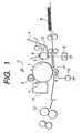
- FIG. 1 An example of an image forming apparatus is schematically shown in Fig. 1, with reference to which an image forming method will be described below.
- Reference numeral 1 denotes a drum type electrophotographic photosensitive member, around which provided are a charging roller (charging member) 2 a primary charging means has, an exposure optical system 3, a developing means 4 having a toner carrying member 5, a transfer means 9 and a cleaning means 11.
- the surface of the electrophotographic photosensitive member 1 is uniformly charged by the operation of the charging roller 2. Thereafter, the charged surface is exposed by the exposure optical system 3 to form an electrostatic latent image on the surface of the electrophotographic photosensitive member 1.
- a toner coat layer is formed by a toner layer thickness regulating member 6, and the electrostatic latent image formed on the electrophotographic photosensitive member 1 is developed in a developing zone while applying an alternating bias, a pulse bias and/or a DC bias across a conductive substrate of the electrophotographic photosensitive member 1 and the toner carrying member 5 through a bias applying means 8.
- reference numeral 7 denotes an agitation means, and 13 a magnetic toner.
- Transfer paper P is delivered to a transfer zone, where the toner image formed by development is electrostatically transferred to transfer paper P by a transfer means, transfer roller 9 while charging the transfer paper P from its back surface through a voltage applying means 10 to a polarity reverse to that of the toner.
- the transfer roller 9 is used as the transfer means.
- it may be a contact charging means such as a transfer blade, or may also be a non-contact, corona transfer means.
- the contact charging means is preferred.
- the transfer paper P to which the toner image has been transferred is passed through a heat-pressure roller fixing assembly 12, thus the toner image turns into a fixed image.
- the toner remaining on the electrophotographic photosensitive member 1 after the transfer step is removed by the operation of a cleaning means cleaning blade 11 and collected in a cleaner 14. After the cleaning, the primary charging step and subsequent steps are repeated.
- plural components among the constituents such as the electrophotographic photosensitive member, the developing means and the cleaning means may be joined integrally as an apparatus unit to make up a process cartridge so that this process cartridge is detachably mountable to the body of the apparatus.
- the charging means and the developing means may be supported integrally in a cartridge together with the electrophotographic photosensitive member to form a process cartridge that is detachable as a single unit from the body of the apparatus through a guide means such as a rail provided in the body of the apparatus.
- the cleaning means may be provided on the side of the process cartridge.
- Fig. 2 shows an embodiment of the process cartridge according to the present invention.
- a process cartridge 16 is exemplified in which a developing means 4, a drum type electrophotographic photosensitive member 1, a cleaner 14 having a cleaning blade 11, and a primary charging member 2 are joined integrally.
- This process cartridge is exchanged by a new cartridge when a magnetic toner 13 of the developing means 4 is used up.
- the developing means 4 holds the magnetic toner 13. At the time of development, a stated electric field is formed across the electrophotographic photosensitive member 1 and a toner carrying member developing sleeve 5. In order for the development to be preferably performed, the distance between the electrophotographic photosensitive member 1 and the developing sleeve 5 is very important.
- the developing means 4 has a toner container 15 which holds the magnetic toner 13, a developing sleeve 5 which carries and transports the magnetic toner 13 from the toner container 15 to the developing zone where it faces the electrophotographic photosensitive member 1, and an elastic blade 6 serving as a toner layer thickness regulating member by which the magnetic toner transported to the developing zone is regulated to form a toner thin layer on the developing sleeve.
- the developing sleeve 5 may have any structure. In usual instances, it comprises a non-magnetic developing sleeve 5 internally provided with a magnet (not shown).
- the developing sleeve 5 may be a cylindrical rotating member as shown in Fig. 2. It may also be a belt which is set circulatively movable. As materials therefor, usually, it is preferable to use aluminum or stainless steel.
- the elastic blade 6 may comprise an elastic plate formed of an elastic rubber such as urethane rubber, silicone rubber or NBR, an elastic metal such as phosphor bronze and stainless steel sheet, or an elastic resin such as polyethylene terephthalate or high-density polyethylene.
- the elastic blade 6 comes into touch with the developing sleeve 5 by its own elasticity, and is fastened to the toner container 15 by means of a support member comprising a rigid material such as iron.
- the elastic blade 6 may preferably come into touch with the developing sleeve 5 in the counter direction with respect to its rotational direction at a linear pressure of from 5 to 80 g/cm.
- a magnetic doctor blade such as an iron blade may also be used.
- a coating fluid comprised of the following materials was coated by dip coating, followed by heat-curing at 140°C for 30 minutes to form a conductive layer with a layer thickness of 15 ⁇ m.
- Conductive pigment SnO 2 -coated barium sulfate 10 parts
- Resistance modifying pigment Titanium oxide 2 parts
- Binder resin Phenol resin 6 parts
- Leveling material Silicone oil 0.001 part
- Solvent Methanol/methoxypropanol (weight ratio:0.2/0.8) 20 parts
- a solution prepared by dissolving 3 parts of N-methoxydimethylated nylon and 3 parts of copolymer nylon in a mixed solvent of 65 parts of methanol and 30 parts of n-butanol was coated by dip coating, followed by drying to form an intermediate layer with a layer thickness of 0.5 ⁇ m.
- TiOPc oxytitanium phthalocyanine
- polyvinyl butyral trade name: S-LEC BM2; available from Sekisui Chemical Co., Ltd.
- 60 parts of cyclohexanone were dispersed for 4 hours by means of a sand grinder making use of glass beads of 1 mm diameter, followed by addition of 100 parts of ethyl acetate to obtain a charge generation layer forming dispersion.
- This dispersion was coated on the intermediate layer by dip coating, followed by drying to form a charge generation layer with a layer thickness of 0.3 ⁇ m.
- tetrafluoroethylene resin particles (trade name: LUBRON L-2; available from Daikin Industries, Ltd.), 10 parts of the resin of Condition No. 1 shown in Table 1 and 0.07 part of a fluorine-containing comb graft polymer (trade name: GF300; available from Toa Kasei K.K.) were thoroughly mixed with 60 parts of monochlorobenzene, followed by dispersion by means of a high-pressure dispersion machine, thus a tetrafluoroethylene resin particle dispersion was prepared.
- the primary particle diameter of tetrafluoroethylene resin particles was measured with a particle size distribution measuring device (manufactured by Horiba Seisakusho) to find that the particle diameter was 0.25 ⁇ m.
- the resultant coating fluid was coated on the charge generation layer by dip coating, followed by drying at 120°C for 2 hours to form a charge transport layer with a layer thickness of 25 ⁇ m.
- a laser beam printer LASER JET 4 PLUS (process speed: 71 mm/sec), manufactured by Hullet Packard Co., having a roller contact charging means as a primary charging member was modified and put into use (DC voltage: -700 V; peak-to-peak voltage of AC voltage: 1.6 kV; frequency: 1 kHz).
- the apparatus was so modified that the controlling of primary charging was changed from constant-current control to constant-voltage control.
- the above modified apparatus was used to make a 2,000 sheet continuous paper-feed running test in environment of 33°C/95%RH, using paper with a moisture absorption of 10% (the moisture absorption was measured with MOISTREX MX5000, manufactured by Infrared Engineering), to make evaluation on smeared images. Images were formed on A4-size sheets in an E-letter pattern with a print image percentage of 4%. Evaluation was made by visually observing E-letter images at the initial stage, on the 2,000-sheet running, and upon leaving for 24 hours after the 2,000-sheet running.
- the peak-to-peak voltage of the AC voltage in the above modified apparatus was changed to 1.9 kV, and a paper-feed running test was made in environment of 15°C/10%RH. Images were formed on A4-size sheets in a lattice pattern with a print image percentage of 4%. Sequence was set in an intermittent mode where copying was stopped once for each sheet. Running was made on up to 5,000 sheets. When any problem occurred on images, the number of sheets on which the problem occurred was recorded. Observation was made visually. Light-area potential at the initial stage and Light-area potential after 5,000-sheet running were measured.
- Electrophotographic photosensitive members were produced in the same manner as in Example 1 except that the resin for the charge transport layer was replaced with the resins of Condition Nos. 2 to 12, respectively, shown in Table 2. Evaluation was made similarly. The results are shown in Table 3.
- Example 1 The procedure of Example 1 was repeated up to the formation of the charge generation layer.
- tetrafluoroethylene resin particles (trade name: LUBRON L-2; available from Daikin Industries, Ltd.), 10 parts of the resin of Condition No. 11 shown in Table 1 and 0.07 part of a fluorine-containing comb graft polymer (trade name: GF300; available from Toa Kasei K.K.) were thoroughly mixed with 60 parts of monochlorobenzene, followed by dispersion by means of a high-pressure dispersion machine, thus a tetrafluoroethylene resin particle dispersion was prepared.
- the primary particle diameter of tetrafluoroethylene resin particles was measured with a particle size distribution measuring device (manufactured by Horiba Seisakusho) to find that the particle diameter was 0.18 ⁇ m.
- the electrophotographic photosensitive member thus obtained was evaluated in the same manner as in Example 1. The results are shown in Table 3.
- An electrophotographic photosensitive member was produced in the same manner as in Example 13 except that the antioxidant was replaced with 0.2 part of a hindered phenol type antioxidant represented by the formula: and 0.2 part of a phosphorus type antioxidant represented by the formula: Evaluation was made similarly. The results are shown in Table 3.
- An electrophotographic photosensitive member was produced in the same manner as in Example 1 except that the resin for the charge transport layer was replaced with the resin of Condition No. 5 shown in Table 1 and the ethylene resin particle dispersion was replaced with the tetrafluoroethylene resin particle dispersion described in Example 13. Evaluation was made similarly. The results are shown in Table 3.
- An electrophotographic photosensitive member was produced in the same manner as in Example 12 except for using fluorine-containing resin particles having a primary particle diameter of 0.35 ⁇ m. Evaluation was made similarly. The results are shown in Table 3.
- An electrophotographic photosensitive member was produced in the same manner as in Example 1 except that the resin for the charge transport layer was replaced with only the resin of Condition No. 13 shown in Table 1. Evaluation was made similarly. The results are shown in Table 4.
- An electrophotographic photosensitive member was produced in the same manner as in Example 8 except that the fluorine-containing resin particles were not used. Evaluation was made similarly. The results are shown in Table 4.
- An electrophotographic photosensitive member was produced in the same manner as in Example 1 except that the fluorine-containing resin particles were not used. Evaluation was made similarly. The results are shown in Table 4.
- An electrophotographic photosensitive member was produced in the same manner as in Example 1 except that the resin for the charge transport layer was replaced with only the resin of Condition No. 14 shown in Table 1. Evaluation was made similarly. The results are shown in Table 4.
- An electrophotographic photosensitive member was produced in the same manner as in Example 5 except that the fluorine-containing resin particles were not used. Evaluation was made similarly. The results are shown in Table 4.
- Binder resin a styrene resin
- Magnetic material Fe 3 O 4
- Charge control agent a monoazo iron complex
- Wax a polymeric alcohol type wax
- a mixture of the above was melt kneaded using a twin extruder heated to 130°C, and the kneaded product obtained was cooled and then crushed by means of a hammer mill.
- the crushed product obtained was pulverized by means of a jet mill, followed by classification using an Elbow Jet classifier to obtain toner particles having the desired particle size distribution.
- hydrophobic fine silica (silicon dioxide) powder having a number-average particle diameter of 0.02 ⁇ m as primary particles and having been surface-treated with a silane coupling agent and 0.3 part of fine strontium titanium powder having a number-average particle diameter of 1.80 ⁇ m as primary particles were added, and these were mixed by means of a Henschel mixer to obtain a toner.
- This toner had a weight-average particle diameter of 5.80 ⁇ m and contained 13% by number of particles having particle diameters of from 2.00 to 3.17 ⁇ m.
- the LJ-5L is an image forming apparatus comprising a contact charging roller coming into contact with the surface of the electrophotographic photosensitive member, used as a primary charging member, where charging voltage of a DC voltage of -625 V in and an AC voltage of 1.8 kV as peak-to-peak voltage and 370 Hz in frequency is applied to the charging roller to charge the electrophotographic photosensitive member primarily.
- Images with an image area percentage of about 3% were continuously printed on 2,500 sheets, and thereafter a solid black image was formed on the whole area of an A4-size recording paper to evaluate the extent to which white dots appeared on the solid black image.
- Images with an image area percentage of about 3% were continuously printed on 2,500 sheets.
- the level of white lines was evaluated by examining a halftone image (one dot/two spaces in the secondary scanning direction) formed after the printing on 2,500 sheets.
- An electrophotographic photosensitive member was produced in the same manner as in Example 1 except that the resin for the charge transport layer was replaced with 6 parts (60% by weight of the whole resin) of the resin of Condition No. 2 shown in Table 1 and 4 parts (40% by weight of the whole resin) of the resin of Condition No. 10 shown in Table 1. Evaluation was made in the same manner as in Example 17. The results are shown in Table 5.
- An electrophotographic photosensitive member was produced in the same manner as in Example 1 except that the resin for the charge transport layer was replaced with 4 parts (40% by weight of the whole resin) of the resin of Condition No. 6 shown in Table 1 and 6 parts (60% by weight of the whole resin) of the resin of Condition No. 11 shown in Table 1. Evaluation was made in the same manner as in Example 17 except for using a toner having a weight-average particle diameter of 6.8 ⁇ m and containing 3% by number of particles having particle diameters of from 2.00 to 3.17 ⁇ m and to which fine silicon dioxide powder was added in an amount of 1.2 parts based on 100 parts of the toner.
- Example 1 The procedure of Example 1 was repeated up to the formation of the charge generation layer.
- tetrafluoroethylene resin particles (trade name: LUBRON L-2; available from Daikin Industries, Ltd.), 10 parts of the resin of Condition No. 1 shown in Table 1 and 0.04 part of a fluorine-containing comb graft polymer (trade name: GF300; available from Toa Kasei K.K.) were thoroughly mixed with 60 parts of monochlorobenzene, followed by dispersion by means of a high-pressure dispersion machine, thus a tetrafluoroethylene resin particle dispersion was prepared.
- the primary particle diameter of tetrafluoroethylene resin particles was measured with a particle size distribution measuring device (manufactured by Horiba Seisakusho) to find that the particle diameter was 0.18 ⁇ m.
- Example 14 in a mixed solvent of 50 parts of monochlorobenzene and 50 parts of dichloromethane, 9 parts and 1 part, 10 parts in total, of the amine compounds as used in Example 1, 10 parts of the resin used in Example 19, 15 parts of the above tetrafluoroethylene resin particle dispersion, 0.2 part of the hindered phenol type antioxidant used in Example 14 and 0.2 part of the phosphorus type antioxidant used in Example 14 were dissolved to obtain a coating fluid.
- This coating fluid was coated on the charge generation layer by dip coating, followed by drying at 120°C for 2 hours to form a charge transport layer with a layer thickness of 25 ⁇ m.
- An electrophotographic photosensitive member was produced in the same manner as in Example 19 except that the tetrafluoroethylene resin particles were not used and the charge transport layer was formed using as the resin 10 parts of only the resin of Condition No. 11 shown in Table 1. Evaluation was made similarly. The results are shown in Table 5.
- An electrophotographic photosensitive member was produced in the same manner as in Example 19 except that the tetrafluoroethylene resin particles were not used and the charge transport layer was formed using as the resin 10 parts of only the resin of Condition No. 6 shown in Table 1. Evaluation was made similarly. The results are shown in Table 5.
- a toner was produced in the same manner as in Example 17 except that the fine strontium titanium powder was not used. Images were formed and evaluated similarly. The results are shown in Table 5.
- a toner was produced in the same manner as in Example 17 except that the fine strontium titanium powder was replaced with fine strontium titanium powder having a number-average particle diameter of 3.5 ⁇ m as primary particles. Images were formed and evaluated similarly. The results are shown in Table 5.
- the toner was produced in the same manner as in Example 17 except that the fine strontium titanium powder was replaced with fine strontium titanium powder having a number-average particle diameter of 0.09 ⁇ m as primary particles. Images were formed and evaluated similarly. The results are shown in Table 5. Structural unit Structural unit Condition No.
- Resin 1 small molecular weight
- Resin 2 large molecular weight
- Proportion (% by weight) Resin used Condition No. in Table 1
- Proportion (% by weight) 1 100 2 2 60 10 40 3 3
- Proportion (% by weight) 1 100 2 2 60 10 40 3 3
- Proportion (% by weight) 1 100 2 2 60 10 40 3 3
- Proportion (% by weight) 1 100 2 2 60 10 40 3 3
- Proportion (% by weight) 1 1 100 2 2 60 10 40 3 3 100 4 4 100 5 5 50 10 50 6 6 40 11 60 7 7 100 8 8 100 9 9 50 12 50 10 6 70 10 30 11 2 30 11 70 12 5 40 11
- Terephthalic acid chloride and isophthalic acid chloride of the polymer represented by Formula (1) were in a mixing ratio of 1:1 in molar ratio.
- a process cartridge which includes an electrophotographic photosensitive member having a photosensitive layer and a charging means.
- the charging means has a charging member which is provided in contact with the electrophotographic photosensitive member to charge the photosensitive member electrostatically by applying a voltage formed by superimposing an alternating-current voltage on a direct-current voltage.
- the photosensitive member has a surface layer which contains at least one of a polyarylate resin having a weight-average molecular weight of 7.5 ⁇ 10 3 to 3.7 ⁇ 10 4 and having a specific structural unit of Formula (1) and a polycarbonate resin having a weight-average molecular weight of 7.5 ⁇ 10 3 to 3.7 ⁇ 10 4 and having a specific structural unit of Formula (2).
- the photosensitive member further contains fluorine-containing resin particles.
- an electrophotographic apparatus having the photosensitive member is disclosed.
Landscapes
- Physics & Mathematics (AREA)
- General Physics & Mathematics (AREA)
- Chemical & Material Sciences (AREA)
- Chemical Kinetics & Catalysis (AREA)
- Spectroscopy & Molecular Physics (AREA)
- Photoreceptors In Electrophotography (AREA)
Applications Claiming Priority (4)
| Application Number | Priority Date | Filing Date | Title |
|---|---|---|---|
| JP12138498 | 1998-04-30 | ||
| JP12032298 | 1998-04-30 | ||
| JP12138498 | 1998-04-30 | ||
| JP12032298 | 1998-04-30 |
Publications (2)
| Publication Number | Publication Date |
|---|---|
| EP0953881A1 true EP0953881A1 (fr) | 1999-11-03 |
| EP0953881B1 EP0953881B1 (fr) | 2005-07-06 |
Family
ID=26457929
Family Applications (1)
| Application Number | Title | Priority Date | Filing Date |
|---|---|---|---|
| EP99108432A Expired - Lifetime EP0953881B1 (fr) | 1998-04-30 | 1999-04-29 | Cartouche de traitement et appareil électrophotographique |
Country Status (5)
| Country | Link |
|---|---|
| US (2) | US6408152B1 (fr) |
| EP (1) | EP0953881B1 (fr) |
| KR (1) | KR100394919B1 (fr) |
| CN (1) | CN1178105C (fr) |
| DE (1) | DE69926032T2 (fr) |
Cited By (1)
| Publication number | Priority date | Publication date | Assignee | Title |
|---|---|---|---|---|
| EP1193559A3 (fr) * | 2000-09-29 | 2002-05-08 | Canon Kabushiki Kaisha | Elément photosensible électrophotographique et cartouche de traitement et appareil électrophotosensible |
Families Citing this family (22)
| Publication number | Priority date | Publication date | Assignee | Title |
|---|---|---|---|---|
| US7480149B2 (en) * | 2004-08-18 | 2009-01-20 | Donnelly Corporation | Accessory module for vehicle |
| EP1383009B1 (fr) * | 2002-07-15 | 2007-12-19 | Canon Kabushiki Kaisha | Elément photosensible électrophotographique, unité de traitement et appareil électrophotographique |
| US20060014097A1 (en) * | 2004-07-14 | 2006-01-19 | Xerox Corporation | Charge transport layer processing |
| WO2006028232A1 (fr) * | 2004-09-10 | 2006-03-16 | Canon Kabushiki Kaisha | Element photosensible electrophotographique, cartouche de traitement et appareil electrophotographique |
| JP5347245B2 (ja) * | 2007-06-28 | 2013-11-20 | 三菱化学株式会社 | 電子写真感光体、電子写真感光体カートリッジ及び画像形成装置 |
| US8475983B2 (en) * | 2010-06-30 | 2013-07-02 | Xerox Corporation | Imaging members having a chemical resistive overcoat layer |
| JP6033097B2 (ja) * | 2013-01-18 | 2016-11-30 | キヤノン株式会社 | 電子写真感光体、プロセスカートリッジおよび電子写真装置 |
| JP2016038577A (ja) | 2014-08-06 | 2016-03-22 | キヤノン株式会社 | 電子写真感光体、プロセスカートリッジおよび電子写真装置 |
| JP6562804B2 (ja) | 2014-09-30 | 2019-08-21 | キヤノン株式会社 | 電子写真感光体、プロセスカートリッジおよび電子写真装置 |
| JP6588731B2 (ja) | 2015-05-07 | 2019-10-09 | キヤノン株式会社 | 電子写真感光体、プロセスカートリッジおよび電子写真装置 |
| US9811012B2 (en) | 2015-09-24 | 2017-11-07 | Canon Kabushiki Kaisha | Electrophotographic photosensitive member, process cartridge, electrophotographic apparatus and process for producing electrophotographic photosensitive member |
| JP6704739B2 (ja) | 2016-01-28 | 2020-06-03 | キヤノン株式会社 | 電子写真感光体、プロセスカートリッジおよび電子写真装置 |
| US9983490B2 (en) | 2016-03-31 | 2018-05-29 | Canon Kabushiki Kaisha | Electrophotographic apparatus |
| JP7060921B2 (ja) | 2017-04-18 | 2022-04-27 | キヤノン株式会社 | 電子写真感光体、プロセスカートリッジおよび電子写真装置 |
| US10241429B2 (en) | 2017-04-27 | 2019-03-26 | Canon Kabushiki Kaisha | Electrophotographic photosensitive member, process cartridge and electrophotographic apparatus |
| JP6983543B2 (ja) | 2017-06-09 | 2021-12-17 | キヤノン株式会社 | 電子写真感光体、プロセスカートリッジおよび電子写真装置 |
| JP6690602B2 (ja) * | 2017-06-12 | 2020-04-28 | 京セラドキュメントソリューションズ株式会社 | 電子写真感光体、プロセスカートリッジ及び画像形成装置 |
| JP6825508B2 (ja) * | 2017-07-21 | 2021-02-03 | 京セラドキュメントソリューションズ株式会社 | 電子写真感光体 |
| JP6918663B2 (ja) | 2017-09-26 | 2021-08-11 | キヤノン株式会社 | 電子写真感光体、プロセスカートリッジおよび電子写真装置 |
| JP7034655B2 (ja) | 2017-10-03 | 2022-03-14 | キヤノン株式会社 | 電子写真感光体、プロセスカートリッジおよび電子写真装置 |
| JP7075288B2 (ja) | 2018-06-05 | 2022-05-25 | キヤノン株式会社 | 電子写真感光体、プロセスカートリッジ及び電子写真装置 |
| JP7358276B2 (ja) * | 2019-03-15 | 2023-10-10 | キヤノン株式会社 | 電子写真画像形成装置及びプロセスカートリッジ |
Citations (4)
| Publication number | Priority date | Publication date | Assignee | Title |
|---|---|---|---|---|
| JPS6365449A (ja) * | 1986-09-08 | 1988-03-24 | Canon Inc | 電子写真感光体 |
| EP0589776A2 (fr) * | 1992-09-21 | 1994-03-30 | Canon Kabushiki Kaisha | Elément électrophotographique photosensible et appareil et bloc d'assemblage électrophotographiques le contenant |
| EP0677794A2 (fr) * | 1994-04-15 | 1995-10-18 | Canon Kabushiki Kaisha | Méthode de formation d'image et unité de traitement |
| US5492786A (en) * | 1993-08-26 | 1996-02-20 | Sharp Kabushiki Kaisha | Electrophotographic photoreceptor |
Family Cites Families (15)
| Publication number | Priority date | Publication date | Assignee | Title |
|---|---|---|---|---|
| US3871880A (en) | 1972-12-01 | 1975-03-18 | Pitney Bowes Inc | Organic photoconductor for electrophotography |
| US3837851A (en) | 1973-01-15 | 1974-09-24 | Ibm | Photoconductor overcoated with triarylpyrazoline charge transport layer |
| JPS6045664B2 (ja) | 1980-04-30 | 1985-10-11 | 株式会社リコー | 新規なジスアゾ化合物およびその製造方法 |
| JPS5717826A (en) | 1980-07-08 | 1982-01-29 | Hitachi Cable Ltd | Temperature measuring method of long metallic wire |
| JPS5840566A (ja) | 1981-09-03 | 1983-03-09 | Kinoshita Kenkyusho:Kk | 電子写真の接触帯電方法 |
| JPS61228453A (ja) | 1985-04-02 | 1986-10-11 | Canon Inc | 電子写真感光体 |
| JPS61272754A (ja) | 1985-05-29 | 1986-12-03 | Canon Inc | 電子写真感光体 |
| JPS62160458A (ja) | 1986-01-09 | 1987-07-16 | Canon Inc | 電子写真感光体 |
| US4933245A (en) * | 1986-09-18 | 1990-06-12 | Fuji Xerox Co., Ltd. | Electrophotographic photoreceptor |
| JPS63149668A (ja) | 1986-12-15 | 1988-06-22 | Canon Inc | 帯電方法及び同装置並びにこの装置を備えた電子写真装置 |
| US5008706A (en) * | 1988-10-31 | 1991-04-16 | Canon Kabushiki Kaisha | Electrophotographic apparatus |
| JPH08254844A (ja) * | 1995-03-16 | 1996-10-01 | Fuji Electric Co Ltd | 電子写真用感光体 |
| US5876890A (en) | 1996-05-27 | 1999-03-02 | Canon Kabushiki Kaisha | Electrophotographic photosensitive member and apparatus and process cartridge provided with the same |
| US5976750A (en) * | 1997-01-28 | 1999-11-02 | Minolta Co., Ltd. | Electrostatic latent image-developing toner containing specified toner particles and specified external additives |
| US5956439A (en) | 1997-09-22 | 1999-09-21 | Lucent Technologies Inc. | Optical switching apparatus for use in the construction mode testing of fibers in an optical cable |
-
1999
- 1999-04-28 US US09/300,479 patent/US6408152B1/en not_active Expired - Lifetime
- 1999-04-29 EP EP99108432A patent/EP0953881B1/fr not_active Expired - Lifetime
- 1999-04-29 DE DE69926032T patent/DE69926032T2/de not_active Expired - Lifetime
- 1999-04-30 KR KR10-1999-0015549A patent/KR100394919B1/ko not_active Expired - Fee Related
- 1999-04-30 CN CNB99107677XA patent/CN1178105C/zh not_active Expired - Fee Related
-
2000
- 2000-07-31 US US09/629,417 patent/US6405005B1/en not_active Expired - Lifetime
Patent Citations (5)
| Publication number | Priority date | Publication date | Assignee | Title |
|---|---|---|---|---|
| JPS6365449A (ja) * | 1986-09-08 | 1988-03-24 | Canon Inc | 電子写真感光体 |
| EP0589776A2 (fr) * | 1992-09-21 | 1994-03-30 | Canon Kabushiki Kaisha | Elément électrophotographique photosensible et appareil et bloc d'assemblage électrophotographiques le contenant |
| EP0903640A2 (fr) * | 1992-09-21 | 1999-03-24 | Canon Kabushiki Kaisha | Elément électrophotographique photosensible et appareil et bloc d'assemblage électrophotographique le contenant. |
| US5492786A (en) * | 1993-08-26 | 1996-02-20 | Sharp Kabushiki Kaisha | Electrophotographic photoreceptor |
| EP0677794A2 (fr) * | 1994-04-15 | 1995-10-18 | Canon Kabushiki Kaisha | Méthode de formation d'image et unité de traitement |
Non-Patent Citations (1)
| Title |
|---|
| DATABASE WPI Section Ch Week 8818, Derwent World Patents Index; Class A14, AN 88-122320, XP002111456 * |
Cited By (2)
| Publication number | Priority date | Publication date | Assignee | Title |
|---|---|---|---|---|
| EP1193559A3 (fr) * | 2000-09-29 | 2002-05-08 | Canon Kabushiki Kaisha | Elément photosensible électrophotographique et cartouche de traitement et appareil électrophotosensible |
| US6541172B2 (en) | 2000-09-29 | 2003-04-01 | Canon Kabushiki Kaisha | Electrophotographic photosensitive member, electrophotographic apparatus and process cartridge |
Also Published As
| Publication number | Publication date |
|---|---|
| KR100394919B1 (ko) | 2003-08-19 |
| EP0953881B1 (fr) | 2005-07-06 |
| US6408152B1 (en) | 2002-06-18 |
| US6405005B1 (en) | 2002-06-11 |
| DE69926032T2 (de) | 2006-05-18 |
| DE69926032D1 (de) | 2005-08-11 |
| CN1178105C (zh) | 2004-12-01 |
| CN1241734A (zh) | 2000-01-19 |
| KR19990083624A (ko) | 1999-11-25 |
Similar Documents
| Publication | Publication Date | Title |
|---|---|---|
| EP0953881B1 (fr) | Cartouche de traitement et appareil électrophotographique | |
| EP1744227B1 (fr) | Appareil de formation d'images avec lame de nettoyage | |
| CN102455614B (zh) | 静电潜像显影剂、成像方法和成像装置 | |
| JP2014098910A (ja) | 画像形成方法 | |
| JP2007293319A (ja) | 画像形成装置 | |
| JP5241098B2 (ja) | 画像形成方法 | |
| US5715501A (en) | Image forming method using a surface with a specified water contact angle and process cartridge using such a method | |
| JP4148505B2 (ja) | 画像形成装置及びプロセスカートリッジ | |
| EP1041449B1 (fr) | Méthode électrophotographique de production d' images, appareil électrophotographique de production d' images et cartouche de traitement | |
| JP4194454B2 (ja) | 画像形成方法 | |
| JP2007033485A (ja) | 画像形成方法及び画像形成装置 | |
| JP4040207B2 (ja) | 画像形成方法及びプロセスカートリッジ | |
| JP2009104126A (ja) | 画像形成装置及びカートリッジ | |
| JP4065508B2 (ja) | 画像形成方法 | |
| JP2005316226A (ja) | 画像形成方法 | |
| JP2006010936A (ja) | 画像形成方法 | |
| JP4018529B2 (ja) | 電子写真感光体 | |
| JP4831726B2 (ja) | 画像形成方法 | |
| JP2005326475A (ja) | 電子写真装置及びプロセスカートリッジ | |
| JP2005234282A (ja) | 画像形成装置及び画像形成方法 | |
| JPH1063026A (ja) | 電子写真感光体、該電子写真感光体を有するプロセスカ−トリッジ及び電子写真装置 | |
| JP3745237B2 (ja) | 画像形成方法及びプロセスカートリッジ | |
| JP4048683B2 (ja) | クリーニングレス電子写真画像形成装置、それを用いる電子写真画像形成方法及びプロセスカートリッジ | |
| JP2003029430A (ja) | 画像形成方法及びプロセスカートリッジ | |
| JP2005164774A (ja) | 画像形成装置 |
Legal Events
| Date | Code | Title | Description |
|---|---|---|---|
| PUAI | Public reference made under article 153(3) epc to a published international application that has entered the european phase |
Free format text: ORIGINAL CODE: 0009012 |
|
| AK | Designated contracting states |
Kind code of ref document: A1 Designated state(s): DE FR GB IT |
|
| AX | Request for extension of the european patent |
Free format text: AL;LT;LV;MK;RO;SI |
|
| 17P | Request for examination filed |
Effective date: 20000322 |
|
| AKX | Designation fees paid |
Free format text: DE FR GB IT |
|
| 17Q | First examination report despatched |
Effective date: 20030919 |
|
| GRAP | Despatch of communication of intention to grant a patent |
Free format text: ORIGINAL CODE: EPIDOSNIGR1 |
|
| GRAS | Grant fee paid |
Free format text: ORIGINAL CODE: EPIDOSNIGR3 |
|
| GRAA | (expected) grant |
Free format text: ORIGINAL CODE: 0009210 |
|
| AK | Designated contracting states |
Kind code of ref document: B1 Designated state(s): DE FR GB IT |
|
| REG | Reference to a national code |
Ref country code: GB Ref legal event code: FG4D |
|
| REF | Corresponds to: |
Ref document number: 69926032 Country of ref document: DE Date of ref document: 20050811 Kind code of ref document: P |
|
| ET | Fr: translation filed | ||
| PLBE | No opposition filed within time limit |
Free format text: ORIGINAL CODE: 0009261 |
|
| STAA | Information on the status of an ep patent application or granted ep patent |
Free format text: STATUS: NO OPPOSITION FILED WITHIN TIME LIMIT |
|
| 26N | No opposition filed |
Effective date: 20060407 |
|
| PGFP | Annual fee paid to national office [announced via postgrant information from national office to epo] |
Ref country code: IT Payment date: 20140402 Year of fee payment: 16 |
|
| PG25 | Lapsed in a contracting state [announced via postgrant information from national office to epo] |
Ref country code: IT Free format text: LAPSE BECAUSE OF NON-PAYMENT OF DUE FEES Effective date: 20150429 |
|
| REG | Reference to a national code |
Ref country code: FR Ref legal event code: PLFP Year of fee payment: 18 |
|
| REG | Reference to a national code |
Ref country code: FR Ref legal event code: PLFP Year of fee payment: 19 |
|
| PGFP | Annual fee paid to national office [announced via postgrant information from national office to epo] |
Ref country code: DE Payment date: 20170430 Year of fee payment: 19 Ref country code: FR Payment date: 20170425 Year of fee payment: 19 Ref country code: GB Payment date: 20170420 Year of fee payment: 19 |
|
| REG | Reference to a national code |
Ref country code: DE Ref legal event code: R119 Ref document number: 69926032 Country of ref document: DE |
|
| GBPC | Gb: european patent ceased through non-payment of renewal fee |
Effective date: 20180429 |
|
| PG25 | Lapsed in a contracting state [announced via postgrant information from national office to epo] |
Ref country code: DE Free format text: LAPSE BECAUSE OF NON-PAYMENT OF DUE FEES Effective date: 20181101 |
|
| PG25 | Lapsed in a contracting state [announced via postgrant information from national office to epo] |
Ref country code: GB Free format text: LAPSE BECAUSE OF NON-PAYMENT OF DUE FEES Effective date: 20180429 |
|
| PG25 | Lapsed in a contracting state [announced via postgrant information from national office to epo] |
Ref country code: FR Free format text: LAPSE BECAUSE OF NON-PAYMENT OF DUE FEES Effective date: 20180430 |