EP0953889B1 - Méthode et dispositif pour détecter et localiser des pannes de capteurs dans les véhicules automobiles - Google Patents
Méthode et dispositif pour détecter et localiser des pannes de capteurs dans les véhicules automobiles Download PDFInfo
- Publication number
- EP0953889B1 EP0953889B1 EP99106074A EP99106074A EP0953889B1 EP 0953889 B1 EP0953889 B1 EP 0953889B1 EP 99106074 A EP99106074 A EP 99106074A EP 99106074 A EP99106074 A EP 99106074A EP 0953889 B1 EP0953889 B1 EP 0953889B1
- Authority
- EP
- European Patent Office
- Prior art keywords
- matrix
- denotes
- value
- residual
- measurement signal
- Prior art date
- Legal status (The legal status is an assumption and is not a legal conclusion. Google has not performed a legal analysis and makes no representation as to the accuracy of the status listed.)
- Expired - Lifetime
Links
- 238000000034 method Methods 0.000 title claims description 20
- 239000011159 matrix material Substances 0.000 claims description 45
- 238000005259 measurement Methods 0.000 claims description 26
- 238000011156 evaluation Methods 0.000 claims description 13
- 230000001133 acceleration Effects 0.000 claims description 4
- 230000003044 adaptive effect Effects 0.000 claims description 2
- 230000003321 amplification Effects 0.000 claims 2
- 238000003199 nucleic acid amplification method Methods 0.000 claims 2
- 238000004364 calculation method Methods 0.000 description 10
- 238000001514 detection method Methods 0.000 description 4
- 230000004807 localization Effects 0.000 description 3
- 230000001419 dependent effect Effects 0.000 description 2
- 230000001953 sensory effect Effects 0.000 description 2
- 230000007547 defect Effects 0.000 description 1
- 230000006866 deterioration Effects 0.000 description 1
- 238000001914 filtration Methods 0.000 description 1
- 230000006870 function Effects 0.000 description 1
Images

Classifications
-
- G—PHYSICS
- G05—CONTROLLING; REGULATING
- G05B—CONTROL OR REGULATING SYSTEMS IN GENERAL; FUNCTIONAL ELEMENTS OF SUCH SYSTEMS; MONITORING OR TESTING ARRANGEMENTS FOR SUCH SYSTEMS OR ELEMENTS
- G05B9/00—Safety arrangements
- G05B9/02—Safety arrangements electric
Definitions
- the invention relates to a method and a device for Detection and localization of errors in sensors in motor vehicles according to the preamble of claim 1 or 14th
- From DE 42 26 746 C1 is a method for determining a known driving situation-dependent steering angle, which serves with a minimum of hardware effort a steering angle setpoint to determine.
- the method is a vehicle system model based on the description variables yaw rate and float angle determines a wheel steering angle, where the deviation of the setpoints from the sensory detected actual values are corrected by means of a state controller becomes.
- X-by-wire systems access electronic Vehicle components active in the driving and the Driving dynamics.
- the control or regulation are the sensory used.
- a defect of a sensor results in an incorrect actual value of the variable concerned, which causes the signals generated by the control, the vehicle dynamics influencing control signals on the Basis of false information being generated, which is an undesirable Reaction of the vehicle and deterioration of the vehicle Driving behavior can cause.
- the invention is based on the problem of errors in sensors for the acquisition of system quantities, which are used to describe the condition of the motor vehicle serve to clearly detect and locate.
- Measurement signals which are recorded by the sensors, flow in a mathematical replacement model, estimated in the state variables which describe the dynamic behavior of the vehicle. These calculated state variables are with a Estimated error whose size is determined and with a Residual is multiplied by the difference of the measured signal and a measurement signal corresponding to the state variables of the mathematical replacement model is formed. From the multiplication of the estimation error with the residuum a characteristic parameter is generated, from which sensor errors are detected and localized can be. The residual is multiplied by the estimation error amplified, causing problems with too low Amplitude and with superimposed system and measurement noise be avoided or compensated.
- the characteristic parameter is used for further evaluation used by an error signal is generated, if the characteristic characteristic exceeds a limit.
- a limit In this Case is the deviation of the measured signal from the calculated one Reference value impermissibly high, so that the characteristic parameter is above the permissible limit and the sensor error can be clearly detected.
- the fault location can also be clearly localized.
- one of the number of sensors generates corresponding number of measuring signals, each exactly one determined from the mathematical replacement model, physically corresponding reference value is assigned.
- Each measuring signal is a residuum and a characteristic of every residuum Characteristic assigned, so that from the position of an inadmissible high, scalar value of the parameter within the vector of all Characteristic parameters on the associated with the characteristic erroneous measuring signal and consequently the faulty sensor can be closed.
- the mathematical replacement model is expediently based on a Kalman filter algorithm. especially on an extended Kalman filter, which corresponds mathematically to an observer and in able to handle stochastic disturbances acting on the system to process.
- the Kalman filter becomes the sensor signals and possibly further system information supplied, from which prediction values, filter estimates and residuals are determined which are further processed for error detection. It can be both simple and without physical redundancy also multiple errors, especially in Radcard- and Longitudinal acceleration sensors are detected.
- the state value of the replacement model corresponds to the prediction value of the Kalman filter passing over the measurement or observation matrix transformed and advantageous for generating the residuals is subtracted from the measured signals. From the prediction values and the residuals can in a next step the optimal Filter estimates are determined, the residuals over a Gain matrix are transformed, preferably the Form of a Kalman gain.
- An occurring sensor error is reflected in a faulty one Predictive value, which differs from the filter estimate of previous time step. This difference between the optimal filter estimate and the prediction value is expressed as an estimation error used to identify a faulty sensor is used.
- the estimation error is multiplied by the residuals amplified, in the case of multi-dimensional state and measured variables from the residuals a diagonal matrix with the elements of the residuum on the main diagonal.
- the on this characteristic characteristic is a typical, Identification feature that can be assigned to a specific sensor used for comparison with the permissible limit can be.
- the limit is adaptively calculated from the weighted Average of individual residuals by the residuals be divided by the number of measuring signals.
- the single ones Residues can also be weighted.
- the wheel speeds of all vehicle wheels and determines the longitudinal acceleration of the vehicle.
- the device for the detection and localization of the sensor errors comprises a calculation unit in which the mathematical replacement model is laid down, and a downstream evaluation unit, the state values and residuals from the calculation unit are fed and generated in the error signal if it is from the state values and the residuals determined characteristic parameter exceeds the limit.
- the device 1 comprises a calculation unit 2 and a Evaluation unit 3; she also has a vehicle controller to influence the dynamic driving behavior of a Motor vehicle included.
- the calculation unit 2 in describe a mathematical replacement model the vehicle system. Bende state variables determined that supplied to the evaluation unit 3 be in the on the basis of the information supplied the decision is made whether the institution 1 supplied signal of a sensor is faulty.
- the measuring unit 2 receives measurement signals y k as discrete-time input signals which represent the vehicle state at times k-1, k, k + 1, etc. Furthermore, the calculation unit 2 is supplied with system information S I as input signals, in particular masses, moments of inertia and the like.
- the system information S I can be stored in a memory unit which communicates with the calculation unit 2 or is integrated in the calculation unit 2.
- x + k x - k + K k * r k .
- r k y k - C k * x - k .
- x - k is the Kalman filter prediction value representing the state value, which is determined immediately before the measurement arrives at time k
- x + k-1 is the Kalman filter optimum filter estimate, which is immediately after the measurement signals are available at time k
- r k denotes the residuals corresponding to the deviation between the measured measured signal y k and the computed transformed predictive value x - k .
- the matrix A denotes the system matrix of the mathematical replacement model in time-discrete form, which can be specified on the basis of equations of motion as a function of vehicle-dependent parameters.
- the matrix B is the time-discrete control matrix over which the input vector u is transformed.
- C k denotes the measuring matrix of the system.
- Q denotes a covariance matrix of the perturbation vector
- G a perturbation matrix for distributing the system noise to the state variables
- R k a distribution density matrix.
- the matrices Q, G and R k take into account stochastic influences.
- the prediction value x - k determined in the calculation unit 2, the optimal filter estimated value x + k-1 and the residuals r k are supplied as input signals to the evaluation unit 3, which is designed as a robust evaluation logic (Residual Evaluation Logic).
- the characteristic parameter ⁇ is based on the decision as to whether a measurement signal y k is outside an admissible frame and accordingly the associated sensor is faulty.
- the estimation error e - k is multiplied from the left by the diagonal matrix R M k , which is occupied on the main diagonal by the components of the vector of the residuals r k . In this calculation method, the characteristic parameter ⁇ is present as a vector.
- the characteristic parameter ⁇ may also be calculated scalar by each component of the vector of estimated values e - k with the associated component of the vector of residuals is multiplied r k. This procedure has the advantage that it is possible to dispense with the generation of the diagonal matrix R M k from the vector of the residuals r k .
- the noise components in the estimation error e - k are very small, so that the signal amplified by the residuals-the characteristic parameter ⁇ -is low-noise and can be used for further evaluation.
- the characteristic parameter ⁇ is compared in the evaluation unit 3 with a limit value s k . If the value of the parameter ⁇ is above the threshold value s k , an error signal E I , E L advantageously consisting of two components is generated which can be displayed or control elements can be supplied in the vehicle.
- the first component E I of the error signal indicates that an error has been detected.
- the second component E L locates the location of the error signal by indicating the position of the faulty component within the vector of the characteristic parameter ⁇ . From this it can be concluded directly on the faulty sensor.
- m denotes the dimension of the vector of the measurement signals y k and M k a weighting matrix, which is preferably determined empirically and with which individual components of the vector of the residuals r k can be weighted more heavily.
- These measuring signals are recorded by sensors during driving.
- the weighting matrix M k has the dimension 5x5 and is in the form in front; the coefficients m ij of the weighting matrix M k are determined empirically.
- the vector of the prediction values is extended by five victim states which contribute to a model improvement, but have no inherent dynamics. These victim states are the road inclination ⁇ and the wheel torques M 1 to M 4 acting on the wheels.
- the slip angles ⁇ 1 , ⁇ 2 , ⁇ 3 , ⁇ 4 at the vehicle wheels can be taken into account as victim states in addition to the road inclination ⁇ .
- a matrix-vector multiplication of the diagonal matrix R M k is performed with the vector of the estimation errors e - k , wherein in the vector of the estimation error e - k only the differences of self-dynamic state variables - the wheel speeds and the longitudinal speed - are taken into account but not the components associated with the victim states.
- the diagonal matrix R M k can also be formulated according to the dimension of the vector of the prediction values as a 10 ⁇ 10 matrix, which is padded with zeros relative to the 5 ⁇ 5 diagonal matrix.
- the vector-matrix multiplication of diagonal matrix R M k and vector of the estimation errors e - k can be performed without reducing the dimension of the estimation error vector.
- the system matrix A has the dimension 10x10, the control matrix B the dimension 10x6, the measurement matrix C k the dimension 5x10, the Kalman gain the dimension 10x5, the estimation error e - k and the characteristic parameter ⁇ the dimension 5x1 and the limit s k the dimension 5x1.
Landscapes
- Physics & Mathematics (AREA)
- General Physics & Mathematics (AREA)
- Engineering & Computer Science (AREA)
- Automation & Control Theory (AREA)
- Feedback Control In General (AREA)
- Control Of Driving Devices And Active Controlling Of Vehicle (AREA)
- Navigation (AREA)
- Vehicle Body Suspensions (AREA)
Claims (14)
- Procédé pour détecter et localiser des pannes de capteurs dans les véhicules automobiles, un signal d'erreur (Er, EL) étant déterminé pour cette détection et localisation desdites pannes de capteurs en utilisant un modèle de remplacement mathématique et en interprétant un signal de mesure (yk) d'une valeur d'état (x- k) et d'un résidu (rk),
caractérisé en ce quele signal de mesure (yk) décrivant le comportement dynamique du véhicule est déterminé par un capteur,la valeur d'état (xk) affectée au signal de mesure (yk) est calculée à partir du modèle de remplacement mathématique,le résidu (rk) est déterminé par la différence entre le signal de mesure (yk) et une grandeur de référence (C*x- k) correspondant au signal de mesure (yk) et formée à partir de la valeur d'état (x- k),une erreur estimative (e- k) de la valeur d'état (x- k) est déterminée,une grandeur caractéristique (ε) est formée à partir de la multiplication du résidu (rk) par l'erreur estimative (e- k), et quele signal d'erreur (Er, EL) est généré lorsque la grandeur caractéristique (ε) dépasse une valeur limite (sk). - Procédé selon la revendication 1,
caractérisé en ce que
le modèle de remplacement mathématique se base sur un algorithme à filtre de Kalman, la valeur d'état étant égale à la valeur de prédiction (x- k) du filtre de Kalman correspondant à la relation
A désigne la matrice système,
B la matrice de commande,
u le vecteur d'entrée,
l'index "-"caractérisant l'instant juste avant l'obtention de la valeur de mesure
l'index "+" l'instant juste à la suite de la disponibilité de la valeur de mesure, et
l'index "k" la représentation de nature discrète dans le temps du système. - Procédé selon la revendication 1 ou 2,
caractérisé en ce que
le résidu (rk) se calcule à partir du signal de mesure (yk) et de la valeur d'état (x- k), en application de la relation
Ck est la matrice de mesure. - Procédé selon l'une quelconque des revendications 1 à 3,
caractérisé en ce que
une valeur estimative filtre optimale (x+ k) est déterminée sur la base de la consigne
Kk est une matrice de gain. - Procédé selon la revendication 4
caractérisé en ce que
la matrice de gain (Kk) est constituée d'un gain Kalman calculé par la relation
Q est une matrice de covariance du vecteur de dérangement,
G est une matrice de dérangement destinée à la répartition du bruit du système sur les grandeurs d'état, et
Rk est une matrice de densité de répartition. - Procédé selon la revendication 4 ou 5,
caractérisé en ce que
l'erreur estimative (e- k) est déterminée par la différence entre la valeur estimative filtre optimale (x+ k-1) et la valeur de prédiction (x- k) sur la base de la relation - Procédé selon la revendication 6,
caractérisé en ce que
la grandeur caractéristique (ε) est déterminée par la relation
RM k désigne une matrice diagonale avec les composantes du résidu sur la diagonale principale. - Procédé selon l'une quelconque des revendications 1 à 7,
caractérisé en ce que
la valeur limite (sk) se calcule de façon adaptive à partir du résidu (rk) sur la base de la consigne
m désigne la dimension du vecteur des signaux de mesure (yk) et
Mk une matrice de pondération. - Procédé selon les revendications précédentes,
caractérisé en ce que
le vecteur des signaux de mesure (yk) prend la forme
m=5
dans laquelle
ω1 à ω4 désignent les vitesses des roues du véhicule, et
ax l'accélération longitudinale du véhicule. - Procédé selon la revendication 9,
caractérisé en ce que
la matrice de pondération (Mk) prend la formeles coefficients (mij) de la matrice de pondération (Mk) étant déterminés de manière empirique.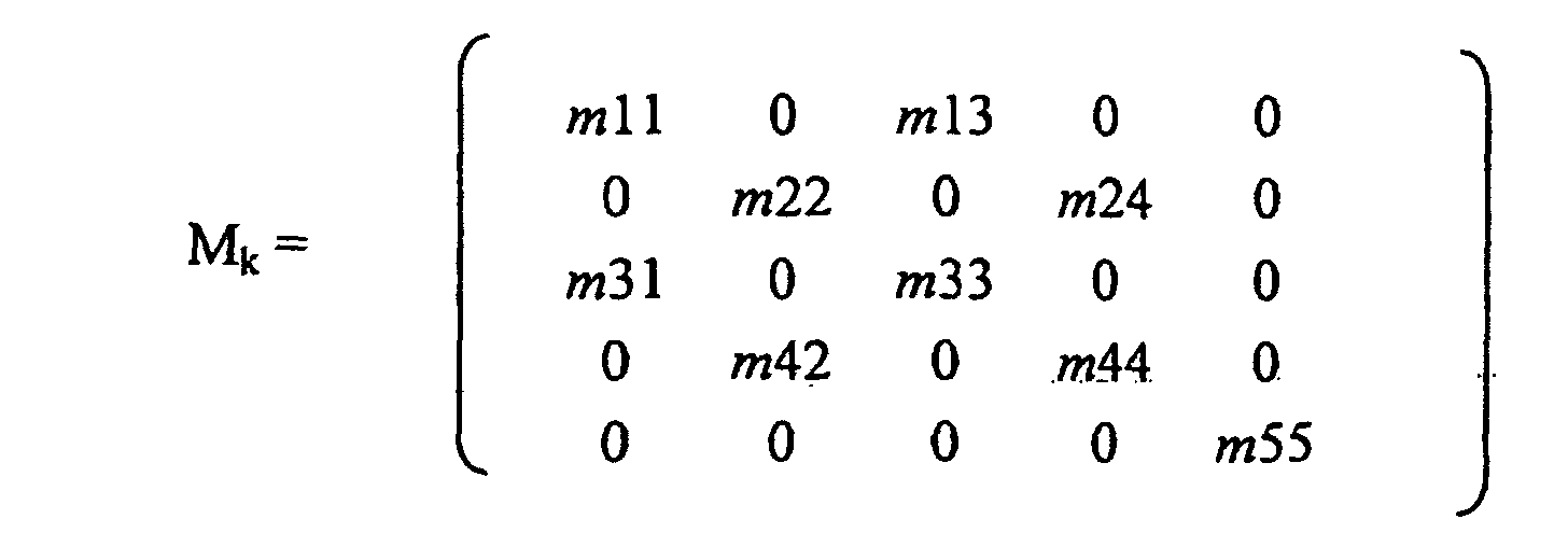
- Procédé selon la revendication 9 ou 10,
caractérisé en ce que
le vecteur des valeurs d'état (x- k) prend la forme
ω1 à ω1 désignent les vitesses des roues,
vx la vitesse longitudinale du véhicule,
l'inclinaison de la route,
M1 à M4 les couples appliqués aux roues, et
lesquels sont compris dans le vecteur d'état en tant qu'états sacrificiels sans dynamique inhérente. - Procédé selon l'une quelconque des revendications 9 à 11,
caractérisé en ce que
la matrice diagonale (RMk) comprenant sur la diagonale principale les composants du résidu (rk) prend la formeseules les différences de grandeurs d'état à dynamique inhérente étant prises en compte dans l'erreur estimative (e- k).
- Procédé selon l'une quelconque des revendications 9 à 12,
caractérisé en ce que
le vecteur d'entrée (uk) prend la forme
k1 à k4 désignent des couples d'entraínement et de freinage ainsi que des couples engendrés par les charges appliquées sur les roues, et
dψ / dt désignant la vitesse d'embardée. - Dispositif destiné à détecter et localiser des pannes de capteurs dans les véhicules automobiles, ledit dispositif comportant une unité de calcul (2) et une unité d'évaluation (3), un signal d'erreurs (Er, EL) étant déterminé pour la détection et localisation desdites pannes de capteurs en utilisant un modèle de remplacement mathématique et en évaluant un signal de mesure (yk), une valeur d'état (X- k) et un résidu (rk),
caractérisé en ce que
le signal de mesure (yk) déterminé par un capteur et décrivant le comportement dynamique du véhicule est envoyé dans l'unité de calcul (2), la valeur d'état (x- k) affectée au signal de mesure (yk) est calculée dans l'unité de calcul (2) à l'aide du modèle de remplacement mathématique implanté dans ladite unité de calcul, par ailleurs, le résidu (rk) calculé en fonction de la différence entre le signal de mesure (yk) et une grandeur de référence (c*x- k) correspondant au signal de mesure (yk) et formé à partir de la valeur d'état (x- k) est déterminé dans l'unité de calcul (2), la valeur d'état (x- k) et le résidu (rk), partant de l'unité de calcul (2), sont envoyés dans l'unité d'évaluation (3), une erreur estimative (e- k) de la valeur d'état (x- k) est déterminée dans l'unité d'évaluation (3), une grandeur caractéristique (ε) découlant de la multiplication du résidu (rk) par l'erreur estimative (e- k) est formée et le signal d'erreurs (Er, EL) est généré lorsque la grandeur caractéristique (ε) dépasse une valeur limite (sk).
Applications Claiming Priority (2)
| Application Number | Priority Date | Filing Date | Title |
|---|---|---|---|
| DE19818860 | 1998-04-28 | ||
| DE19818860A DE19818860C2 (de) | 1998-04-28 | 1998-04-28 | Verfahren und Einrichtung zur Detektion und Lokalisation von Sensorfehlern in Kraftfahrzeugen |
Publications (3)
| Publication Number | Publication Date |
|---|---|
| EP0953889A2 EP0953889A2 (fr) | 1999-11-03 |
| EP0953889A3 EP0953889A3 (fr) | 1999-11-10 |
| EP0953889B1 true EP0953889B1 (fr) | 2004-06-23 |
Family
ID=7865982
Family Applications (1)
| Application Number | Title | Priority Date | Filing Date |
|---|---|---|---|
| EP99106074A Expired - Lifetime EP0953889B1 (fr) | 1998-04-28 | 1999-03-26 | Méthode et dispositif pour détecter et localiser des pannes de capteurs dans les véhicules automobiles |
Country Status (5)
| Country | Link |
|---|---|
| US (1) | US6470300B1 (fr) |
| EP (1) | EP0953889B1 (fr) |
| JP (1) | JP3341158B2 (fr) |
| DE (1) | DE19818860C2 (fr) |
| ES (1) | ES2221256T3 (fr) |
Families Citing this family (28)
| Publication number | Priority date | Publication date | Assignee | Title |
|---|---|---|---|---|
| DE10015225A1 (de) * | 1999-08-25 | 2001-04-05 | Continental Teves Ag & Co Ohg | Verfahren und Vorrichtung zur Ermittlung einer konsolidierten Eingangsgröße |
| JP3618274B2 (ja) * | 2000-03-21 | 2005-02-09 | トヨタ自動車株式会社 | 車両用センサ異常検出装置 |
| US6766230B1 (en) * | 2000-11-09 | 2004-07-20 | The Ohio State University | Model-based fault detection and isolation system and method |
| US6687585B1 (en) * | 2000-11-09 | 2004-02-03 | The Ohio State University | Fault detection and isolation system and method |
| GB2377494B (en) * | 2001-07-09 | 2004-07-28 | Autoliv Dev | "Improvements in or relating to an off-set elimination system for a vibrating gyroscope" |
| DE10211130A1 (de) * | 2002-03-14 | 2003-09-25 | Zahnradfabrik Friedrichshafen | Verfahren zur Optimierung der Lebensdauer von Komponenten und/oder Bauteilen eines Kraftfahrzeugs |
| GB0303477D0 (en) * | 2003-02-14 | 2003-03-19 | Ricardo Consulting Eng | On board diagnostics (OBD) |
| DE10315344B8 (de) * | 2003-04-03 | 2010-02-11 | Audi Ag | Verfahren und Vorrichtung zur Erkennung fehlerhafter Komponenten in Fahrzeugen |
| DE10333171A1 (de) * | 2003-07-22 | 2005-02-24 | Robert Bosch Gmbh | Verfahren zur Überwachung eines Teilsystems |
| DE102005030731B4 (de) * | 2004-07-06 | 2014-05-08 | Schaeffler Technologies Gmbh & Co. Kg | Vorrichtung zum Überprüfen der Drehzahl eines Kraftfahrzeugrades |
| DE102005019017B4 (de) * | 2005-04-21 | 2007-01-18 | Iav Gmbh Ingenieurgesellschaft Auto Und Verkehr | Verfahren und Vorrichtung zur Fehlerdiagnose für Verbrennungsmotoren |
| DE102007027768B4 (de) * | 2006-06-22 | 2008-09-18 | Sauer-Danfoss Aps | Ein Flüssigkeitsregler und Verfahren zur Feststellung eines Fehlers in einem Flüssigkeitsregler |
| ITBO20070399A1 (it) * | 2007-06-04 | 2008-12-05 | Rhoss S P A | Metodo per stimare il carico termico di un circuito per un fluido di servizio in uscita da una macchina frigorifera |
| US7827008B2 (en) * | 2008-10-21 | 2010-11-02 | General Electric Company | System including phase signal saving during anomaly and related method |
| DE102010002504B4 (de) * | 2010-03-02 | 2017-02-09 | TAKATA Aktiengesellschaft | Verfahren und Vorrichtung zum Überprüfen einer elektronischen Einrichtung |
| CN102012241A (zh) * | 2010-09-21 | 2011-04-13 | 深圳市元征软件开发有限公司 | 基于传感器特性的汽车传感器故障检测方法 |
| KR102041093B1 (ko) | 2011-04-11 | 2019-11-06 | 크라운 이큅먼트 코포레이션 | 조정된 경로 계획기를 사용하는 다수의 자동화 비-홀로노믹 차량들을 효율적으로 스케줄링하는 방법 및 장치 |
| US8548671B2 (en) * | 2011-06-06 | 2013-10-01 | Crown Equipment Limited | Method and apparatus for automatically calibrating vehicle parameters |
| US20140058634A1 (en) | 2012-08-24 | 2014-02-27 | Crown Equipment Limited | Method and apparatus for using unique landmarks to locate industrial vehicles at start-up |
| US9056754B2 (en) | 2011-09-07 | 2015-06-16 | Crown Equipment Limited | Method and apparatus for using pre-positioned objects to localize an industrial vehicle |
| DE102012221896B4 (de) | 2012-01-03 | 2022-02-03 | Schaeffler Technologies AG & Co. KG | Verfahren zur Ermittlung eines Tastpunkts einer Reibungskupplung |
| DE102012209387A1 (de) * | 2012-06-04 | 2013-12-05 | Robert Bosch Gmbh | Verfahren und Vorrichtung zum Überwachen eines Stellgebersystems |
| DE102014200426B4 (de) * | 2014-01-13 | 2025-03-20 | Bayerische Motoren Werke Aktiengesellschaft | Verfahren zur robusten Erkennung von hochfrequenten Signalstörungen |
| DE102015009253A1 (de) * | 2015-07-17 | 2017-01-19 | Liebherr-Werk Bischofshofen Gmbh | Lenksystem für eine Arbeitsmaschine |
| DE102016015268B4 (de) * | 2016-12-21 | 2019-06-06 | Compagnie Générale Des Etablissements Michelin | Verfahren zur Ansteuerung einer Fahrzeugbremsanlage zur Optimierung des Bremsvorganges |
| AT521735A1 (de) * | 2018-09-19 | 2020-04-15 | Siemens Mobility GmbH | Verfahren und Vorrichtung zur Diagnose und Überwachung von Fahrzeugkomponenten |
| DE102020112200A1 (de) * | 2019-09-03 | 2021-03-04 | Schaeffler Technologies AG & Co. KG | Elektrische Antriebseinheit, Verfahren zum Betreiben einer elektrischen Antriebseinheit und Verfahren zur Temperaturberechnung |
| DE102024130788B3 (de) * | 2024-10-22 | 2025-12-31 | Fraba B.V. | Sensorvorrichtung |
Family Cites Families (11)
| Publication number | Priority date | Publication date | Assignee | Title |
|---|---|---|---|---|
| DE4100006A1 (de) * | 1991-01-02 | 1992-07-09 | Joerg Dr Zaschel | Universelles massestrommessgeraet fuer fluessigkeiten, gase und feststoffe |
| DE4216301C2 (de) * | 1992-05-16 | 1997-05-22 | Daimler Benz Ag | Verfahren zur Bestimmung das Fahrverhalten charakterisierender Größen |
| US5548536A (en) | 1992-05-16 | 1996-08-20 | Daimler-Benz Ag | Method for determining quantities which characterize the driving behavior |
| DE4226749C2 (de) | 1992-08-13 | 1996-02-08 | Daimler Benz Ag | Verfahren zur Bestimmung das Fahrverhalten charakterisierender Größen |
| DE4325413C2 (de) | 1993-07-29 | 1995-05-18 | Daimler Benz Ag | Verfahren zur Bestimmung des Fahrverhalten charakterisierender Größen |
| DE19515057B4 (de) * | 1994-11-25 | 2006-08-03 | Continental Teves Ag & Co. Ohg | Bremsanlage für ein Kraftfahrzeug |
| US6014598A (en) * | 1996-06-28 | 2000-01-11 | Arcelik A.S. | Model-based fault detection system for electric motors |
| DE19636443A1 (de) | 1996-09-07 | 1998-03-12 | Bosch Gmbh Robert | Vorrichtung und Verfahren zur Überwachung von Sensoren in einem Fahrzeug |
| US5918951A (en) * | 1997-05-09 | 1999-07-06 | The B.F. Goodrich Company | Antiskid brake control system using kalman filtering |
| US5911127A (en) * | 1997-06-05 | 1999-06-08 | Carrier Corporation | Prediction of chiller compressor motor overheating |
| US6144904A (en) * | 1998-12-22 | 2000-11-07 | Ford Global Technologies, Inc. | Instant detection / diagnosis of abrupt bias fault in signals of vehicle motion sensors |
-
1998
- 1998-04-28 DE DE19818860A patent/DE19818860C2/de not_active Expired - Fee Related
-
1999
- 1999-03-26 ES ES99106074T patent/ES2221256T3/es not_active Expired - Lifetime
- 1999-03-26 EP EP99106074A patent/EP0953889B1/fr not_active Expired - Lifetime
- 1999-04-21 JP JP15037499A patent/JP3341158B2/ja not_active Expired - Fee Related
- 1999-04-28 US US09/300,590 patent/US6470300B1/en not_active Expired - Lifetime
Also Published As
| Publication number | Publication date |
|---|---|
| EP0953889A2 (fr) | 1999-11-03 |
| JP2000035441A (ja) | 2000-02-02 |
| US6470300B1 (en) | 2002-10-22 |
| ES2221256T3 (es) | 2004-12-16 |
| DE19818860C2 (de) | 2001-04-19 |
| JP3341158B2 (ja) | 2002-11-05 |
| EP0953889A3 (fr) | 1999-11-10 |
| DE19818860A1 (de) | 1999-11-11 |
Similar Documents
| Publication | Publication Date | Title |
|---|---|---|
| EP0953889B1 (fr) | Méthode et dispositif pour détecter et localiser des pannes de capteurs dans les véhicules automobiles | |
| EP2755868B1 (fr) | Système capteur comportant une unité de modèle de véhicule | |
| EP2771714B1 (fr) | Système de détection conçu pour une autoévaluation de l'intégrité de ses données | |
| EP0932033B1 (fr) | Procédé et appareil pour la détermination de la masse d'un véhicule | |
| DE4325413C2 (de) | Verfahren zur Bestimmung des Fahrverhalten charakterisierender Größen | |
| EP1692026B1 (fr) | Procede et systeme de surveillance d'un dispositif de mesure dispose dans un vehicule a roues | |
| DE10353650A1 (de) | System zum Analysieren eines Fahrzeug- und Fahrerverhaltens | |
| DE102017116196A1 (de) | Erkennung und rekonstruktion von sensorfehlern | |
| DE69612224T2 (de) | Verfahren zur Bestimmung von Reifendruck bei fahrendem Fahrzeug | |
| DE19803386A1 (de) | Vorrichtung zur Überwachung des Luftdrucks eines Fahrzeugreifens | |
| DE102011110012A1 (de) | Diagnoseverfahren zur Verwendung mit einem dynamischen Fahrzeugsteuersystem (VDCS) | |
| DE102011108292A1 (de) | Verfahren zum Betrieb einer Fahrerassistenzvorrichtung | |
| WO2015189184A1 (fr) | Procédé et système d'initialisation d'un système de fusion de capteurs | |
| DE102020112107A1 (de) | Vorrichtung und Verfahren zum Abschätzen eines Neigungswinkels einer Straße | |
| DE102012224420A1 (de) | Verfahren und System für das Messen des Neigungswinkels während des Abbiegens eines Fahrzeugs | |
| DE102014211180A1 (de) | Verfahren und System zur verbesserten Erkennung und/oder Kompensation von Fehlerwerten | |
| DE102019118213A1 (de) | Verfahren und Steuereinheit zur Schätzung eines Modellparameters eines fahrdynamischen Modells eines Fahrzeugs | |
| DE10133170A1 (de) | Beschleunigungssensor-Fehlerdetektor | |
| DE102017222776A1 (de) | Verfahren und System zum Bestimmen einer Zahnstangenkraft, Betriebsassistenzverfahren für eine Arbeitsvorrichtung, Betriebsassistenzvorrichtung und Arbeitsvorrichtung | |
| DE10360728A1 (de) | Verfahren und Vorrichtung zur Bestimmung eines Fahrzeugzustandes | |
| DE102014211164A1 (de) | Verfahren und System zur Anpassung eines Navigationssystems | |
| DE68913459T2 (de) | Vorrichtung und Verfahren zur Bestimmung von Fehlern in den Daten eines magnetischen Richtungssensors. | |
| DE102014211178A1 (de) | Verfahren und System zur Korrektur von Messdaten eines ersten Sensorsystems | |
| EP1993888B1 (fr) | Procede et dispositif pour limiter les interventions de reglage d'un regulateur de vehicule | |
| DE102016219471A1 (de) | Verfahren und Steuergerät zu Erkennung der Fahrtrichtung eines Fahrzeugs |
Legal Events
| Date | Code | Title | Description |
|---|---|---|---|
| PUAI | Public reference made under article 153(3) epc to a published international application that has entered the european phase |
Free format text: ORIGINAL CODE: 0009012 |
|
| PUAL | Search report despatched |
Free format text: ORIGINAL CODE: 0009013 |
|
| AK | Designated contracting states |
Kind code of ref document: A2 Designated state(s): ES FR GB IT |
|
| AX | Request for extension of the european patent |
Free format text: AL;LT;LV;MK;RO;SI |
|
| AK | Designated contracting states |
Kind code of ref document: A3 Designated state(s): AT BE CH CY DE DK ES FI FR GB GR IE IT LI LU MC NL PT SE |
|
| AX | Request for extension of the european patent |
Free format text: AL;LT;LV;MK;RO;SI |
|
| 17P | Request for examination filed |
Effective date: 19991104 |
|
| AKX | Designation fees paid |
Free format text: ES FR GB IT |
|
| REG | Reference to a national code |
Ref country code: DE Ref legal event code: 8566 |
|
| 17Q | First examination report despatched |
Effective date: 20021122 |
|
| GRAP | Despatch of communication of intention to grant a patent |
Free format text: ORIGINAL CODE: EPIDOSNIGR1 |
|
| GRAS | Grant fee paid |
Free format text: ORIGINAL CODE: EPIDOSNIGR3 |
|
| GRAA | (expected) grant |
Free format text: ORIGINAL CODE: 0009210 |
|
| AK | Designated contracting states |
Kind code of ref document: B1 Designated state(s): ES FR GB IT |
|
| REG | Reference to a national code |
Ref country code: GB Ref legal event code: FG4D Free format text: NOT ENGLISH |
|
| GBT | Gb: translation of ep patent filed (gb section 77(6)(a)/1977) |
Effective date: 20040722 |
|
| REG | Reference to a national code |
Ref country code: ES Ref legal event code: FG2A Ref document number: 2221256 Country of ref document: ES Kind code of ref document: T3 |
|
| ET | Fr: translation filed | ||
| PLBE | No opposition filed within time limit |
Free format text: ORIGINAL CODE: 0009261 |
|
| STAA | Information on the status of an ep patent application or granted ep patent |
Free format text: STATUS: NO OPPOSITION FILED WITHIN TIME LIMIT |
|
| 26N | No opposition filed |
Effective date: 20050324 |
|
| PGFP | Annual fee paid to national office [announced via postgrant information from national office to epo] |
Ref country code: FR Payment date: 20060313 Year of fee payment: 8 |
|
| PGFP | Annual fee paid to national office [announced via postgrant information from national office to epo] |
Ref country code: ES Payment date: 20060329 Year of fee payment: 8 |
|
| PGFP | Annual fee paid to national office [announced via postgrant information from national office to epo] |
Ref country code: IT Payment date: 20060331 Year of fee payment: 8 |
|
| GBPC | Gb: european patent ceased through non-payment of renewal fee |
Effective date: 20070326 |
|
| REG | Reference to a national code |
Ref country code: FR Ref legal event code: ST Effective date: 20071130 |
|
| PG25 | Lapsed in a contracting state [announced via postgrant information from national office to epo] |
Ref country code: GB Free format text: LAPSE BECAUSE OF NON-PAYMENT OF DUE FEES Effective date: 20070326 |
|
| REG | Reference to a national code |
Ref country code: ES Ref legal event code: FD2A Effective date: 20070327 |
|
| PG25 | Lapsed in a contracting state [announced via postgrant information from national office to epo] |
Ref country code: FR Free format text: LAPSE BECAUSE OF NON-PAYMENT OF DUE FEES Effective date: 20070402 Ref country code: ES Free format text: LAPSE BECAUSE OF NON-PAYMENT OF DUE FEES Effective date: 20070327 |
|
| PGFP | Annual fee paid to national office [announced via postgrant information from national office to epo] |
Ref country code: GB Payment date: 20060322 Year of fee payment: 8 |
|
| PG25 | Lapsed in a contracting state [announced via postgrant information from national office to epo] |
Ref country code: IT Free format text: LAPSE BECAUSE OF NON-PAYMENT OF DUE FEES Effective date: 20070326 |