EP2771714B1 - Système de détection conçu pour une autoévaluation de l'intégrité de ses données - Google Patents
Système de détection conçu pour une autoévaluation de l'intégrité de ses données Download PDFInfo
- Publication number
- EP2771714B1 EP2771714B1 EP12787662.1A EP12787662A EP2771714B1 EP 2771714 B1 EP2771714 B1 EP 2771714B1 EP 12787662 A EP12787662 A EP 12787662A EP 2771714 B1 EP2771714 B1 EP 2771714B1
- Authority
- EP
- European Patent Office
- Prior art keywords
- sensor
- information
- datum
- signal processing
- physical variable
- Prior art date
- Legal status (The legal status is an assumption and is not a legal conclusion. Google has not performed a legal analysis and makes no representation as to the accuracy of the status listed.)
- Active
Links
Images


Classifications
-
- G—PHYSICS
- G01—MEASURING; TESTING
- G01C—MEASURING DISTANCES, LEVELS OR BEARINGS; SURVEYING; NAVIGATION; GYROSCOPIC INSTRUMENTS; PHOTOGRAMMETRY OR VIDEOGRAMMETRY
- G01C21/00—Navigation; Navigational instruments not provided for in groups G01C1/00 - G01C19/00
- G01C21/10—Navigation; Navigational instruments not provided for in groups G01C1/00 - G01C19/00 by using measurements of speed or acceleration
- G01C21/12—Navigation; Navigational instruments not provided for in groups G01C1/00 - G01C19/00 by using measurements of speed or acceleration executed aboard the object being navigated; Dead reckoning
- G01C21/16—Navigation; Navigational instruments not provided for in groups G01C1/00 - G01C19/00 by using measurements of speed or acceleration executed aboard the object being navigated; Dead reckoning by integrating acceleration or speed, i.e. inertial navigation
- G01C21/165—Navigation; Navigational instruments not provided for in groups G01C1/00 - G01C19/00 by using measurements of speed or acceleration executed aboard the object being navigated; Dead reckoning by integrating acceleration or speed, i.e. inertial navigation combined with non-inertial navigation instruments
-
- G—PHYSICS
- G01—MEASURING; TESTING
- G01S—RADIO DIRECTION-FINDING; RADIO NAVIGATION; DETERMINING DISTANCE OR VELOCITY BY USE OF RADIO WAVES; LOCATING OR PRESENCE-DETECTING BY USE OF THE REFLECTION OR RERADIATION OF RADIO WAVES; ANALOGOUS ARRANGEMENTS USING OTHER WAVES
- G01S19/00—Satellite radio beacon positioning systems; Determining position, velocity or attitude using signals transmitted by such systems
- G01S19/38—Determining a navigation solution using signals transmitted by a satellite radio beacon positioning system
- G01S19/39—Determining a navigation solution using signals transmitted by a satellite radio beacon positioning system the satellite radio beacon positioning system transmitting time-stamped messages, e.g. GPS [Global Positioning System], GLONASS [Global Orbiting Navigation Satellite System] or GALILEO
- G01S19/42—Determining position
- G01S19/48—Determining position by combining or switching between position solutions derived from the satellite radio beacon positioning system and position solutions derived from a further system
- G01S19/49—Determining position by combining or switching between position solutions derived from the satellite radio beacon positioning system and position solutions derived from a further system whereby the further system is an inertial position system, e.g. loosely-coupled
-
- A—HUMAN NECESSITIES
- A01—AGRICULTURE; FORESTRY; ANIMAL HUSBANDRY; HUNTING; TRAPPING; FISHING
- A01C—PLANTING; SOWING; FERTILISING
- A01C1/00—Apparatus, or methods of use thereof, for testing or treating seed, roots, or the like, prior to sowing or planting
-
- B—PERFORMING OPERATIONS; TRANSPORTING
- B60—VEHICLES IN GENERAL
- B60R—VEHICLES, VEHICLE FITTINGS, OR VEHICLE PARTS, NOT OTHERWISE PROVIDED FOR
- B60R16/00—Electric or fluid circuits specially adapted for vehicles and not otherwise provided for; Arrangement of elements of electric or fluid circuits specially adapted for vehicles and not otherwise provided for
- B60R16/02—Electric or fluid circuits specially adapted for vehicles and not otherwise provided for; Arrangement of elements of electric or fluid circuits specially adapted for vehicles and not otherwise provided for electric constitutive elements
-
- B—PERFORMING OPERATIONS; TRANSPORTING
- B60—VEHICLES IN GENERAL
- B60W—CONJOINT CONTROL OF VEHICLE SUB-UNITS OF DIFFERENT TYPE OR DIFFERENT FUNCTION; CONTROL SYSTEMS SPECIALLY ADAPTED FOR HYBRID VEHICLES; ROAD VEHICLE DRIVE CONTROL SYSTEMS FOR PURPOSES NOT RELATED TO THE CONTROL OF A PARTICULAR SUB-UNIT
- B60W30/00—Purposes of road vehicle drive control systems not related to the control of a particular sub-unit, e.g. of systems using conjoint control of vehicle sub-units
- B60W30/14—Adaptive cruise control
-
- B—PERFORMING OPERATIONS; TRANSPORTING
- B60—VEHICLES IN GENERAL
- B60W—CONJOINT CONTROL OF VEHICLE SUB-UNITS OF DIFFERENT TYPE OR DIFFERENT FUNCTION; CONTROL SYSTEMS SPECIALLY ADAPTED FOR HYBRID VEHICLES; ROAD VEHICLE DRIVE CONTROL SYSTEMS FOR PURPOSES NOT RELATED TO THE CONTROL OF A PARTICULAR SUB-UNIT
- B60W50/00—Details of control systems for road vehicle drive control not related to the control of a particular sub-unit, e.g. process diagnostic or vehicle driver interfaces
-
- G—PHYSICS
- G01—MEASURING; TESTING
- G01C—MEASURING DISTANCES, LEVELS OR BEARINGS; SURVEYING; NAVIGATION; GYROSCOPIC INSTRUMENTS; PHOTOGRAMMETRY OR VIDEOGRAMMETRY
- G01C21/00—Navigation; Navigational instruments not provided for in groups G01C1/00 - G01C19/00
- G01C21/10—Navigation; Navigational instruments not provided for in groups G01C1/00 - G01C19/00 by using measurements of speed or acceleration
- G01C21/12—Navigation; Navigational instruments not provided for in groups G01C1/00 - G01C19/00 by using measurements of speed or acceleration executed aboard the object being navigated; Dead reckoning
- G01C21/16—Navigation; Navigational instruments not provided for in groups G01C1/00 - G01C19/00 by using measurements of speed or acceleration executed aboard the object being navigated; Dead reckoning by integrating acceleration or speed, i.e. inertial navigation
-
- G—PHYSICS
- G01—MEASURING; TESTING
- G01D—MEASURING NOT SPECIALLY ADAPTED FOR A SPECIFIC VARIABLE; ARRANGEMENTS FOR MEASURING TWO OR MORE VARIABLES NOT COVERED IN A SINGLE OTHER SUBCLASS; TARIFF METERING APPARATUS; MEASURING OR TESTING NOT OTHERWISE PROVIDED FOR
- G01D1/00—Measuring arrangements giving results other than momentary value of variable, of general application
-
- G—PHYSICS
- G06—COMPUTING OR CALCULATING; COUNTING
- G06F—ELECTRIC DIGITAL DATA PROCESSING
- G06F17/00—Digital computing or data processing equipment or methods, specially adapted for specific functions
- G06F17/10—Complex mathematical operations
- G06F17/18—Complex mathematical operations for evaluating statistical data, e.g. average values, frequency distributions, probability functions, regression analysis
-
- G—PHYSICS
- G01—MEASURING; TESTING
- G01S—RADIO DIRECTION-FINDING; RADIO NAVIGATION; DETERMINING DISTANCE OR VELOCITY BY USE OF RADIO WAVES; LOCATING OR PRESENCE-DETECTING BY USE OF THE REFLECTION OR RERADIATION OF RADIO WAVES; ANALOGOUS ARRANGEMENTS USING OTHER WAVES
- G01S19/00—Satellite radio beacon positioning systems; Determining position, velocity or attitude using signals transmitted by such systems
- G01S19/38—Determining a navigation solution using signals transmitted by a satellite radio beacon positioning system
- G01S19/39—Determining a navigation solution using signals transmitted by a satellite radio beacon positioning system the satellite radio beacon positioning system transmitting time-stamped messages, e.g. GPS [Global Positioning System], GLONASS [Global Orbiting Navigation Satellite System] or GALILEO
- G01S19/42—Determining position
- G01S19/45—Determining position by combining measurements of signals from the satellite radio beacon positioning system with a supplementary measurement
- G01S19/47—Determining position by combining measurements of signals from the satellite radio beacon positioning system with a supplementary measurement the supplementary measurement being an inertial measurement, e.g. tightly coupled inertial
Definitions
- the invention relates to a sensor system according to the preamble of claim 1 and its use in motor vehicles, especially in automobiles.
- Offenlegungsschrift DE 10 2010 063 984 A1 describes a sensor system comprising a plurality of sensor elements and a signal processing device, wherein the signal processing device is designed so that the output signals of the sensor elements are evaluated together.
- the function of a Kalman filter is the estimation of a system state of a system. Often, the system state can not be measured directly, but can only be estimated based on known system behavior and measurable, indirectly or directly related to the system state to be estimated measurements. For this purpose, measured values of different measured variables, but also measured values based on different measuring principles, can be used.
- the Kalman filter provides an uncertainty factor of the estimated value determined for each fusion process performed. The uncertainty factor of the estimated value is based on the uncertainty factors of the measured values considered as well as on the uncertainty factors the previously performed estimations.
- the invention is based on the object to propose a sensor system which provides or allows a relatively high intrinsic safety with respect to its signal processing and / or which is suitable for safety-critical applications or a safety-critical use.
- the invention describes a sensor system comprising a plurality of sensor elements that are designed such that they at least partially detect different primary measured variables and / or at least partially use different measuring principles, further comprising a signal processing device, wherein the signal processing device has a fusion filter which is designed such that it at least partially jointly evaluates the sensor signals of the sensor elements and evaluates the information quality of at least one physical quantity, in particular at least partially, based on sensor signals from sensor elements which directly detect this physical quantity or from whose sensor signals this physical quantity can be calculated is, wherein the signal processing means comprises an integrity unit, which is designed so that it contains information about the consistency of the at least one n the date of physical size provides, with the information is calculated on the consistency of this date of this physical quantity at least on the basis of directly or indirectly redundantly present sensor information, the integrity unit as information about the consistency to the at least one date of physical size provides a relative confidence measure as relative confidence information, which depends on the relative deviation of the data and / or measured values of at least two sensor information source channels on the basis of which the corresponding
- a primary measured variable is preferably understood as the measured variable for the detection of which the sensor element is mainly designed and which is detected directly in particular.
- sensor information is preferably meant which is provided by parallel redundancy, as direct redundancy or by analytical redundancy, as indirect redundancy.
- the signal processing device preferably comprises an integrity unit in which the information about the consistency is generated.
- the signal processing device has a fusion filter which, in the course of the joint evaluation of at least the sensor signals and / or signals derived therefrom, provides a defined fusion data set, this fusion data set each having data on defined physical quantities, the fusion data set being at least one physical size includes a date of this physical quantity and information about the consistency of this date of physical size.
- the signal processing device is designed such that the defined fusion data set additionally has at least one status data of a sensor element which itself provides the sensor element by means of a self-diagnosis, whereby this status data is taken into account in the calculation of the information about the consistency of at least one date of a physical variable becomes.
- the signal processing device is designed such that it uses one measured value and / or one measurement information and / or one value derived from a measurement information per sensor information source channel and an uncertainty measure of this sensor information source channel for calculating the relative confidence information.
- the signal processing device is designed such that, in addition to or as a substitute for a relative confidence measure, it provides an absolute confidence measure as absolute confidence information as information about the consistency with at least one physical quantity datum, which depends on an uncertainty measure of at least two Sensor information source channels on the basis of which the corresponding at least one physical quantity datum is calculated.
- the signal processing device is designed such that at least one datum of a physical variable is evaluated, whether or not the consistency is sufficiently large, this evaluation being carried out by calculating whether the relative confidence information and / or the relative confidence measure exceeds a defined threshold.
- the signal processing device is designed in such a way that only a single sensor information source channel is available and / or only a single sensor information channel is available in a defined time interval in which the data of at least one sensor information source channel is used to calculate the information about the consistency Date is provided, no relative confidence measure is calculated and that in this case the absolute confidence measure is assumed to be 0 or a value to infinity or a defined value, or that the absolute confidence measure in this case is not calculated.
- An uncertainty measure is preferably understood to be a scattering measure and / or a scattering and / or a variance and / or an accuracy or a measure of accuracy which can be calculated or converted from the uncertainty measure.
- the uncertainty measure depends on or follows a probability density function or a standard deviation or a variance.
- the probability density function is dependent in particular on the mean value of the probability distribution and the standard deviation of the probability distribution.
- the sensor system uses the information about the consistency for a system test or a validation, in which it is determined on the basis of threshold values of consistency, whether the sensor system is working sufficiently error-free or not.
- the sensor system uses the consistency information to monitor the operation of the sensor system.
- the associated densities are known, for example, from the specifications of the measured data.
- the relative confidence or the relative confidence measure or the relative confidence measure is particularly preferably evaluated and / or calculated on a measured time basis by the probability densities being set around the measured values ⁇ i and multiplying these points by point.
- the signal processing device has a fusion filter which, in the course of the joint evaluation of at least the sensor signals and / or signals of the sensor elements derived therefrom, provides a defined fusion data set, this fusion data set each having data on defined physical quantities, wherein the fusion data set for at least one physical size comprises a value of this physical quantity and information about its data quality.
- the output signals or - are understood data of the sensor elements or sensor information source channels.
- the fusion filter is preferably designed as a Kalman filter, alternatively preferably as a particle filter, or alternatively as an information filter or alternatively as an "unscented" Kalman filter.
- the fusion filter is embodied such that the fusion data set comprises as the value of the at least one physical variable a relative value, in particular an offset value and / or change value and / or correction value and / or error value.
- the relative values of the respective physical quantities of the fusion data set are correction values to which scattering information or scattering or scattering measure, in particular variance, is assigned as information about their data quality.
- the fusion filter is configured such that the value of at least one physical quantity of the fusion data set is calculated on the direct or indirect basis of sensor signals of a plurality of sensor elements, wherein These sensor elements detect this at least one physical size redundant in a direct or indirect manner.
- This redundant detection is particularly preferably realized direct or parallel redundancy and / or realized as analytical redundancy, from mathematically derived or derived variables / values and / or model assumptions.
- the fusion filter is preferably designed as a Kalman filter, which iteratively performs at least prediction steps and correction steps and at least partially provides the fusion data set.
- the fusion filter is designed as an error state space extended sequential Kalman filter, ie as a Kalman filter, which particularly preferably comprises a linearization and in which error state information is calculated and / or estimated and / or which operates sequentially and thereby in the respective functional step of the sequence available / considered available input data.
- the sensor system has an inertial sensor arrangement, comprising at least one acceleration sensor element and at least one yaw rate sensor element, and that the sensor system comprises a strapdown algorithm unit, in which a strapdown algorithm is carried out, with which at least the sensor signals of the inertial sensor arrangement, in particular corrected, navigation data and / or vehicle dynamics data are processed, based on the vehicle in which the sensor system is arranged.
- the strapdown algorithm unit provides its computed navigation data and / or vehicle dynamics data directly or indirectly to the fusion filter.
- the sensor system preferably has an inertial sensor arrangement which is designed such that it can detect at least the acceleration along a second defined axis, in particular the transverse axis of the vehicle, and at least the rotation rate about a third defined axis, in particular the high axis of the vehicle the first and the third defined axis form a generator system, and in particular are oriented perpendicular to one another, wherein the sensor system further comprises at least one wheel speed sensor element, in particular at least or exactly four wheel speed sensor elements which detect the wheel speed of a wheel or the wheel speeds of each of the wheels of the vehicle and in particular additionally detect the direction of rotation of the associated wheel of the vehicle, in which the sensor system is arranged wherein the sensor system additionally comprises at least one steering angle sensor element which detects the steering angle of the vehicle and wherein the sensor system further comprises a satellite navigation system, which is designed in particular such that it maps the distance data respectively between the associated satellite and the vehicle or one of them Size and speed information data respectively between the associated satellite and the vehicle or a dependent size detected and /
- the inertial sensor arrangement is designed such that it can detect at least the accelerations along a first, a second and a third defined axis and at least the rotation rates about this first, about this second and about this third defined axis, said first, second and third third defined axis form a generating system, and in particular are each aligned perpendicular to each other.
- the inertial sensor assembly provide its sensor signals to the strapdown algorithm unit and the strapdown algorithm unit is configured to at least from the sensor signals of the inertial sensor arrangement and in particular at least one error state information and / or variance and / or information about the data quality which is assigned to a sensor signal or a physical variable and is provided by the fusion filter, as measured variables and / or navigation data and / or vehicle dynamics data at least corrected accelerations along the first, second and third defined axes, at least corrected rotation rates around these three defined Axes, at least one speed with respect to these three defined axes and at least one position size calculated and / or provided.
- the sensor system is embodied such that in each case at least one sensor signal and / or a physical variable as the direct or derived size of the inertial sensor arrangement and / or the strapdown algorithm unit, the wheel speed sensor elements and the steering angle sensor element, in particular indirectly via a vehicle model unit, and the satellite navigation system, in particular distance data in each case between the assigned satellite and the vehicle or a variable dependent thereon as well as speed information data in each case between the assigned satellite and the vehicle or a variable dependent thereon, supplied to the fusion filter and taken into account by the fusion filter in its calculations.
- the vehicle model unit is configured such that from the sensor signals of the wheel speed sensor elements and the steering angle sensor element, the speed along the first defined axis, the speed along the second defined axis and the rate of rotation about the third axis defined be calculated.
- the vehicle model unit is designed such that it uses a method of least squares for solving an overdetermined equation system, in particular known as a least-squared error method.
- the signal processing device is preferably designed such that the fusion filter calculates and / or provides and / or outputs the fusion data set at defined times.
- the fusion filter is preferably designed such that it calculates and / or provides the fusion data set independently of the sampling rates and / or sensor signal output times of the sensor elements, in particular the wheel speed sensor elements and the steering angle sensor element, and independent of temporal signal or Meß relien- / or information output times of the satellite navigation system and / or outputs.
- the signal processing device is designed so that in the course of a functional step of the fusion filter always, in particular asynchronously, the latest available to the fusion filter information and / or signals and / or data the sensor elements, in particular the wheel speed sensor elements and the steering angle sensor element, directly or indirectly, in particular by means of the vehicle model unit and the satellite navigation system directly or indirectly, be updated sequentially and / or included in the fusion filter and taken into account in the calculation of the associated function step of the fusion filter.
- the invention also relates to the use of the sensor system in vehicles, in particular motor vehicles, particularly preferably in automobiles.
- the invention additionally relates in particular to a method which is executed or carried out in the sensor system and by the above Design options - / possibilities of the sensor system with regard to the possible variants of the method is disclosed.
- Fig. 1 shows a schematic representation of an embodiment of the sensor system, which is intended for arrangement and use in a vehicle.
- the sensor elements and the satellite navigation system as well as the most important signal processing units of the signal processing device are illustrated as function blocks and their interaction with each other.
- the sensor system comprises an inertial measurement unit 1, IMU, which is designed such that it has at least the accelerations along a first, a second and a third defined axis and at least the rotation rates about these first, second and third third axis defined, wherein the first defined axis corresponds to the longitudinal axis of the vehicle, the second defined axis corresponds to the transverse axis of the vehicle and the third defined axis corresponds to the vertical axis of the vehicle.
- IMU inertial measurement unit
- the sensor system has a strapdown algorithm unit 2 in which a strapdown algorithm is carried out, with which at least the sensor signals of the inertial sensor arrangement 1 are processed into corrected navigation data and / or vehicle dynamics data.
- This output data of the strapdown algorithm unit 2 comprises the data of the following physical quantities: the speed, the acceleration and the rate of rotation of each of the vehicle, for example with respect to the three axes of the vehicle coordinate system and, for example, additionally in each case based on a world coordinate system, which is suitable for describing the orientation and / or dynamic sizes of the vehicle in the world.
- the output data of the strapdown algorithm unit 2 includes the position with respect to the vehicle coordinate system and the orientation with respect to the world coordinate system.
- the output data of the strapdown algorithm unit has the variances as information about the data quality of the above physical quantities, at least some of them. For example, these variances are not calculated in the strapdown algorithm unit, but only used and forwarded by it.
- the output data of the strapdown algorithm unit are also exemplary the output data or output data 12 of the entire sensor system.
- the sensor system also includes wheel speed sensor elements 3 for each wheel of the vehicle, for example, four, which detect the wheel speeds each one of the wheels of the vehicle and each additionally detect the direction of rotation, and additionally a steering angle sensor element 3, which detects the steering angle of the vehicle.
- the wheel speed sensor element and the steering angle sensor element form a sensor arrangement 3 for detecting the odometry.
- the sensor system comprises a satellite navigation system 4, which is designed such that it records the distance data respectively between the assigned satellite and the vehicle or a dependent thereon size and speed information data respectively between the associated satellite and the vehicle or a dependent size and / / or provides.
- the satellite navigation system 4 provides start position information, at least for starting or turning on the sensor system, to the fusion filter.
- the signal processing device of the sensor system also includes a fusion filter 5.
- the fusion filter 5 is in the course of the joint evaluation of at least the sensor signals and / or signals derived therefrom of the sensor elements 3, so the odometry, and the output signals of the satellite navigation system 4 and / or signals derived therefrom a defined Fusion data set 6 ready.
- This fusion data set in each case has data on defined physical variables, the fusion data set 6 being at least one physical size includes a value of this physical quantity and information about its data quality, this information about the data quality is exemplarily pronounced as a variance.
- the fusion data set 6 comprises as a value of the at least one physical variable a relative value, for example a correction value, also called an offset value.
- a relative value for example a correction value, also called an offset value.
- the correction value results in each case from the accumulated error values or change values which are provided by the fusion filter 5.
- the relative values of the respective physical quantities of the fusion data set 6 are therefore, for example, correction values and variances.
- the fusion data record 6 calculates, in other words, a fault budget, which is provided as the input variable or input data record of the strapdown algorithm unit and is at least partially taken into account in its calculations.
- This error budget comprises as a data set or output data at least correction values or error values of physical quantities and in each case a variance, as information about the data quality, for each value.
- the fusion filter at least the correction values and variances to the physical quantities speed, acceleration and rotation rate, each based on the vehicle coordinate system, ie each of the three components of these sizes with respect to this coordinate system, and IMU orientation or the IMU orientation angle between the vehicle coordinate system and the coordinate system or the mounting orientation of the inertial sensor arrangement 1 as well as the position with respect to the world coordinate system are transmitted to the strapdown algorithm unit.
- the values of the physical quantities of the fusion data set are calculated on the direct and indirect basis of the sensor signals of the sensor elements 3 and the satellite navigation system 4, whereby at least some quantities, for example the speed and the position of the vehicle with respect to the vehicle coordinates are redundant to the data of the strapdown algorithm. Unit 2 are collected and recycled.
- the fusion filter 5 is designed, for example, as an error state space extended sequential Kalman filter, that is to say as a Kalman filter, which in particular comprises a linearization and in which the correction values are calculated and / or estimated and which operates sequentially and which in the respective functional step of FIG Sequence available input data used / considered.
- the fusion filter 5 is designed so that in the course of a functional step of the fusion filter always, asynchronously, the latest, the fusion filter available information and / or signals and / or data the sensor elements 3, so the wheel speed sensor elements and the steering angle sensor element indirectly by means of a vehicle model unit 7 and of the satellite navigation system 4 directly or indirectly, be updated sequentially and / or included in the fusion filter and taken into account in the calculation of the associated operating step of the fusion filter 5.
- the vehicle model unit 7 is designed to be at least one of the sensor signals of the wheel speed sensor elements 3 and of the steering angle sensor element 3 the velocity along a first defined axis, the velocity along a second defined axis, and the rate of rotation about a third defined axis are calculated and provided to the fusion filter 5.
- the sensor system has, for example, four wheel speed sensor elements 3, wherein one of the wheel speed sensor elements is assigned to each wheel of the vehicle, wherein the vehicle model unit 7 is designed to be composed of the sensor signals of the wheel speed sensor elements and the steering angle provided by the steering angle sensor unit and / or the steering angle each wheel, in particular detected by the steering angle sensor element for the front wheels and by means of at least one further steering angle sensor element for the rear wheels or at least from a model assumption for the rear wheels, calculates, directly or indirectly, the speed components and / or the speed, of each wheel, along / with respect to the first and second defined axes, of which eight speed components and / or the four speeds respectively with respect to the first and second defined axis, the velocity is calculated along a first defined axis, the velocity along a second defined axis, and the rate of rotation about a third defined axis.
- the sensor system or its signal processing device also comprises a tire parameter estimation unit 10, which is designed such that it calculates at least the radius, for example the dynamic radius, of each wheel and additionally calculates the skew stiffness and the slip stiffness of each wheel and makes it available to the vehicle model unit 7 as additional input variables, wherein the tire parameter estimation unit 10 is configured to use a substantially linear tire model to calculate wheel / tire sizes.
- the exemplary input variables of the tire parameter estimation unit are the wheel speeds 3 and the steering angle 3, at least partially or completely the output variables or values of the strapdown algorithm unit 2, in particular the variances provided by it in addition to the values of the physical quantities, as well as the variances of the fusion filter 5, to the physical quantities which are the input variables of the tire parameter estimation unit 10.
- the sensor system or its signal processing device also includes a GPS error detection and plausibility unit 11, which is designed such that it receives, for example as input data, the output data or output signals of the satellite navigation system 4 and at least partially the output data or output signals of the strapdown algorithm unit 2 and taken into account in their calculations
- the GPS error detection and plausibility unit 11 is additionally connected to the fusion filter 5 and exchanges data therewith.
- the sensor system or its signal processing device also has a standstill detection unit 8, which is designed so that it can detect a standstill of the vehicle and, in the case of a detected standstill of the vehicle at least provides the fusion filter 5 information from a standstill model, in particular the information that the rotation rates around all three axes have the value zero and at least one position change quantity likewise has the value zero and in particular the speeds along all three axes have the value zero.
- the standstill detection unit 8 is designed such that it uses the wheel speeds or wheel speed signals as input data as well as the "raw" or direct output signals of the inertial sensor arrangement 1.
- the signal processing device calculates and / or uses By way of example, a first group of physical quantity data whose values relate to a vehicle coordinate system and additionally calculates and / or uses a second group of physical quantity data whose values relate to a world coordinate system, wherein said world coordinate system is at least descriptive of orientation and / or or of dynamic quantities of the vehicle in the world, the sensor system having an alignment model unit 9 with which the alignment angle between the vehicle coordinate system and the world coordinate system is calculated.
- the alignment angle between the vehicle coordinate system and the world coordinate system in the alignment model unit 9 is calculated based at least on the following quantities: the speed with respect to the vehicle coordinate system, the speed with respect to the world coordinate system, and the steering angle.
- the alignment model unit 9 uses some or all of the output data and / or output signals of the strapdown algorithm unit 2 for calculation.
- the alignment model unit 9 is configured, for example, to calculate and provide, in addition to the orientation angle, information about the data quality of this size, in particular the variance of the orientation angle, wherein the alignment model unit 9 determines the alignment angle between the vehicle coordinate system and the world coordinate system and the information about the data quality of this size to the fusion filter 5, and the fusion filter uses this orientation angle in its calculations, and most preferably, passes the information about the data quality of that size, in particular the variance of the orientation angle, to the strapdown algorithm unit 2.
- the signal processing device of the sensor system is designed, for example, such that it provides information about the consistency of at least one datum of a physical quantity, wherein this datum of physical quantity is at least partially calculated on the basis of the sensor signals from sensor elements which directly detect or exclude this physical variable whose sensor signals this physical quantity can be calculated, wherein the information about the consistency of this date of this physical quantity is calculated at least on the basis of directly or indirectly redundantly present sensor information.
- the signal processing unit is designed in such a way that it calculates and provides a relative confidence measure to the values of all the physical variables of the fusion data set and also an absolute confidence measure.
Landscapes
- Engineering & Computer Science (AREA)
- Radar, Positioning & Navigation (AREA)
- Remote Sensing (AREA)
- Physics & Mathematics (AREA)
- General Physics & Mathematics (AREA)
- Computer Networks & Wireless Communication (AREA)
- Automation & Control Theory (AREA)
- Data Mining & Analysis (AREA)
- Life Sciences & Earth Sciences (AREA)
- Mechanical Engineering (AREA)
- Mathematical Optimization (AREA)
- Pure & Applied Mathematics (AREA)
- Mathematical Analysis (AREA)
- Theoretical Computer Science (AREA)
- Computational Mathematics (AREA)
- Mathematical Physics (AREA)
- Transportation (AREA)
- Software Systems (AREA)
- Bioinformatics & Cheminformatics (AREA)
- Probability & Statistics with Applications (AREA)
- Databases & Information Systems (AREA)
- Operations Research (AREA)
- General Engineering & Computer Science (AREA)
- Bioinformatics & Computational Biology (AREA)
- Algebra (AREA)
- Evolutionary Biology (AREA)
- Environmental Sciences (AREA)
- Soil Sciences (AREA)
- Human Computer Interaction (AREA)
- Navigation (AREA)
- Combined Controls Of Internal Combustion Engines (AREA)
Claims (10)
- Système de détection comprenant une pluralité d'éléments de détection conçus pour détecter au moins partiellement différentes grandeurs de mesure primaires et/ou pour utiliser au moins partiellement différents principes de mesure, comprenant en outre un dispositif de traitement de signaux, dans lequel
le dispositif de traitement de signaux comporte un filtre de fusion (5) qui est conçu pour évaluer de manière au moins partiellement commune les signaux de détection des éléments de détection, pour analyser la qualité des informations des signaux de détection et pour calculer au moins une donnée d'une grandeur physique, en particulier au moins partiellement sur la base des signaux de détection d'éléments de détection qui détectent directement ladite grandeur physique ou dont les signaux de détection permettent de calculer la grandeur physique,
caractérisé en ce que le dispositif de traitement de signaux comprend une unité d'intégrité conçue pour fournir une information concernant la cohérence de l'au moins une donnée de la grandeur physique, dans lequel l'information concernant la cohérence de ladite donnée de ladite grandeur physique est calculée au moins sur la base des informations de détection disponibles de manière directement ou indirectement redondante, dans lequel l'unité d'intégrité fournit, en tant qu'information concernant la cohérence de l'au moins une donnée de la grandeur physique, une mesure de confiance relative, en tant qu'information de confiance relative, qui dépend de l'écart relatif des données et/ou de valeurs de mesure d'au moins deux canaux de sources d'informations de détection sur la base desquelles l'au moins une donnée correspondante de la grandeur physique est calculée. - Système de détection selon la revendication 1, caractérisé en ce que le dispositif de traitement de signaux comporte un filtre de fusion (5) qui fournit un ensemble de données de fusion (6) défini au cours de l'évaluation commune d'au moins les signaux de détection et/ou de signaux dérivés de ceux-ci des éléments de détection, dans lequel ledit ensemble de données de fusion comporte respectivement des données pour des grandeurs physiques définies, dans lequel l'ensemble de données de fusion (6) comprend pour au moins une grandeur physique une donnée de ladite grandeur physique et une information concernant la cohérence de ladite donnée de la grandeur physique.
- Système de détection selon au moins l'une des revendications 1 ou 2, caractérisé en ce que le dispositif de traitement de signaux est conçu de manière à ce que l'ensemble de données de fusion défini comporte en outre au moins une donnée d'état d'un élément de détection, laquelle donnée d'état fournit elle-même l'élément de détection au moyen d'un autodiagnostic, dans lequel ladite donnée d'état est prise en compte lors du calcul de l'information concernant la cohérence d'au moins une donnée d'une grandeur physique.
- Système de détection selon au moins l'une des revendications 1 à 3, caractérisé en ce que le dispositif de traitement de signaux est conçu de manière à utiliser respectivement, pour chaque canal de source d'informations de détection, une valeur de mesure et/ou une information de mesure et/ou une valeur dérivée d'une information de mesure et une mesure d'incertitude dudit canal de source d'informations de détection pour calculer l'information de confiance relative.
- Système de détection selon au moins l'une des revendications 1 à 4, caractérisé en ce que le dispositif de traitement de signaux est conçu de manière à ce que, pour l'au moins une donnée d'une grandeur physique, l'information de confiance relative associée soit calculée en tant que mesure de confiance relative Kr, où
 et où n est défini ou définissable comme étant le nombre des canaux de sources d'informations de détection comparées,pi , la fonction de densité de probabilité du i-ème canal de source d'informations de détection, et en particulier µi, la valeur moyenne de la distribution de probabilité, σ i , l'écart-type de la distribution de probabilité, et x, la variable d'intégration.
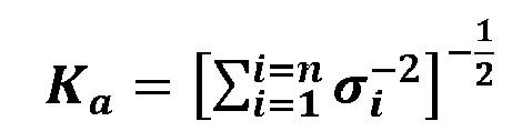
 - Système de détection selon au moins l'une des revendications 1 à 5, caractérisé en ce que le dispositif de traitement de signaux est conçu de manière à fournir, en plus d'une mesure de confiance relative en tant qu'information concernant la cohérence pour au moins une donnée d'une grandeur physique, une mesure de confiance absolue en tant qu'information de confiance absolue, qui dépend d'une mesure d'incertitude d'au moins deux canaux de sources d'informations de détection sur la base desquels l'au moins une donnée correspondante de la grandeur physique est calculée.
- Système de détection selon la revendication 6, caractérisé en ce que le dispositif de traitement de signaux est conçu de manière à ce que, pour l'au moins une donnée d'une grandeur physique, l'information de confiance absolue associée soit calculée comme étant la mesure de confiance absolue Ka, avec

- Système de détection selon au moins l'une des revendications 1 à 7, caractérisé en ce que le dispositif de traitement de signaux est conçu de manière à ce qu'une évaluation soit effectuée pour au moins une donnée d'une grandeur physique, pour déterminer si la cohérence est suffisamment élevée ou non, dans lequel ladite évaluation est effectuée en déterminant par calcul si l'information de confiance relative et/ou la mesure de confiance relative dépasse une valeur de seuil définie.
- Système de détection selon au moins l'une des revendications 1 à 8, caractérisé en ce qu'une disparition d'un canal de source d'informations de détection est prise en compte dans le calcul des informations concernant la cohérence.
- Système de détection selon la revendication 9, caractérisé en ce que le dispositif de traitement de signaux est conçu de manière à ce que, dans le cas où, au cours d'un intervalle de temps défini dans lequel les données d'au moins un canal de source d'informations de détection sont utilisées pour calculer les informations concernant la cohérence, un seul canal de source d'informations de détection est disponible et/ou un seul canal d'informations de détection fournit une donnée, aucune mesure de confiance relative n'est calculée et en ce que, dans ce cas, la valeur 0 ou une valeur rapportée à l'infini ou une valeur définie est prise pour la mesure de confiance absolue ou en ce que la mesure de confiance absolue n'est dans ce cas pas calculée.
Applications Claiming Priority (4)
| Application Number | Priority Date | Filing Date | Title |
|---|---|---|---|
| DE102011085134 | 2011-10-24 | ||
| DE102011086710 | 2011-11-21 | ||
| DE102012207297 | 2012-05-02 | ||
| PCT/EP2012/071092 WO2013060750A1 (fr) | 2011-10-24 | 2012-10-24 | Système de détection conçu pour une autoévaluation de l'intégrité de ses données |
Publications (3)
| Publication Number | Publication Date |
|---|---|
| EP2771714A1 EP2771714A1 (fr) | 2014-09-03 |
| EP2771714B1 true EP2771714B1 (fr) | 2018-08-08 |
| EP2771714B8 EP2771714B8 (fr) | 2018-10-24 |
Family
ID=47191701
Family Applications (2)
| Application Number | Title | Priority Date | Filing Date |
|---|---|---|---|
| EP12787661.3A Ceased EP2771713A1 (fr) | 2011-10-24 | 2012-10-24 | Système de détection conçu pour une autoévaluation de la précision de ses données |
| EP12787662.1A Active EP2771714B8 (fr) | 2011-10-24 | 2012-10-24 | Système de détection conçu pour une autoévaluation de l'intégrité de ses données |
Family Applications Before (1)
| Application Number | Title | Priority Date | Filing Date |
|---|---|---|---|
| EP12787661.3A Ceased EP2771713A1 (fr) | 2011-10-24 | 2012-10-24 | Système de détection conçu pour une autoévaluation de la précision de ses données |
Country Status (6)
| Country | Link |
|---|---|
| US (2) | US9558157B2 (fr) |
| EP (2) | EP2771713A1 (fr) |
| KR (2) | KR20140093961A (fr) |
| CN (2) | CN104011563B (fr) |
| DE (2) | DE102012219478A1 (fr) |
| WO (2) | WO2013060749A1 (fr) |
Families Citing this family (39)
| Publication number | Priority date | Publication date | Assignee | Title |
|---|---|---|---|---|
| KR20140070722A (ko) * | 2012-11-26 | 2014-06-11 | 한국전자통신연구원 | 다중속도시스템 결합 장치 및 운용 방법 |
| US20150102955A1 (en) * | 2013-10-14 | 2015-04-16 | GM Global Technology Operations LLC | Measurement association in vehicles |
| DE102014211178A1 (de) | 2013-11-20 | 2015-06-25 | Continental Teves Ag & Co. Ohg | Verfahren und System zur Korrektur von Messdaten eines ersten Sensorsystems |
| DE102014211168A1 (de) | 2014-06-11 | 2015-12-17 | Continental Teves Ag & Co. Ohg | Verfahren und System zur Verifizierung von Messdaten |
| DE102014211172A1 (de) * | 2014-06-11 | 2015-12-17 | Continental Teves Ag & Co. Ohg | Verfahren und System zur Korrektur von Ausgabedaten eines Sensorbasissystems |
| DE102014211171A1 (de) * | 2014-06-11 | 2015-12-17 | Continental Teves Ag & Co. Ohg | Verfahren und System zur Anpassung eines Navigationssystems |
| DE102014211164A1 (de) | 2014-06-11 | 2015-12-17 | Continental Teves Ag & Co. Ohg | Verfahren und System zur Anpassung eines Navigationssystems |
| DE102014211180A1 (de) | 2014-06-11 | 2015-12-17 | Continental Teves Ag & Co. Ohg | Verfahren und System zur verbesserten Erkennung und/oder Kompensation von Fehlerwerten |
| DE102014211177A1 (de) | 2014-06-11 | 2015-12-17 | Continental Teves Ag & Co. Ohg | Verfahren und System zur echtzeitfähigen Bereitstellung von dynamischen Fehlerwerten dynamischer Messwerte |
| DE102014211175A1 (de) | 2014-06-11 | 2015-12-17 | Continental Teves Ag & Co. Ohg | Verfahren und System zur Initialisierung eines Sensorfusionssystems |
| CN104061928B (zh) * | 2014-06-26 | 2017-05-03 | 北京控制工程研究所 | 一种自主择优使用星敏感器信息的方法 |
| DE102014212703A1 (de) * | 2014-07-01 | 2016-01-07 | Continental Teves Ag & Co. Ohg | M2XPro-Überwachung durch Integritätsmaßspeicherung |
| JP6269566B2 (ja) | 2015-05-08 | 2018-01-31 | トヨタ自動車株式会社 | 誤認識判定装置 |
| DE102015209467A1 (de) | 2015-05-22 | 2016-11-24 | Continental Teves Ag & Co. Ohg | Verfahren zur Schätzung von Fahrstreifen |
| US11501867B2 (en) * | 2015-10-19 | 2022-11-15 | Medtronic Minimed, Inc. | Medical devices and related event pattern presentation methods |
| US11666702B2 (en) | 2015-10-19 | 2023-06-06 | Medtronic Minimed, Inc. | Medical devices and related event pattern treatment recommendation methods |
| DE102016217079A1 (de) * | 2016-09-08 | 2018-03-08 | Robert Bosch Gmbh | Verfahren und Vorrichtung zum Betreiben eines ersten Fahrzeugs |
| JP6805791B2 (ja) * | 2016-12-14 | 2020-12-23 | 株式会社Ihi | 情報処理装置、情報処理方法及び情報処理システム |
| JP6885781B2 (ja) | 2017-05-11 | 2021-06-16 | 日立Astemo株式会社 | 車両制御装置、車両制御方法および車両制御システム |
| DE102017213577A1 (de) | 2017-08-04 | 2019-02-07 | Robert Bosch Gmbh | Verfahren zur Lagebestimmung eines Roboters, Lagebestimmungsvorrichtung eines Roboters und Roboter |
| US20190054915A1 (en) * | 2017-08-16 | 2019-02-21 | Deere & Company | Service Brake Assist Steering |
| DE102017216755A1 (de) * | 2017-09-21 | 2019-03-21 | Continental Automotive Gmbh | Verfahren zur Bestimmung einer Fehlerfortpflanzung von Steuersignalen |
| DE102017216749A1 (de) * | 2017-09-21 | 2019-03-21 | Continental Automotive Gmbh | Verfahren zur Bereitstellung eines Steuersignals |
| EP3470861B1 (fr) * | 2017-10-10 | 2019-11-27 | Melexis Technologies SA | Détection de défaillance de capteur redondant |
| DE102018206829A1 (de) * | 2018-05-03 | 2019-11-07 | Continental Automotive Gmbh | Adaption eines Steuersignals anhand von der Signalgenauigkeit |
| EP3653428A1 (fr) * | 2018-11-19 | 2020-05-20 | B&R Industrial Automation GmbH | Procédé de surveillance sûre du fonctionnement d'un moteur linéaire à stator long |
| DE102018220936A1 (de) * | 2018-12-04 | 2020-06-04 | Robert Bosch Gmbh | Verfahren zur Überprüfung eines Sensorwertes eines MEMS-Sensors |
| DE102018222166A1 (de) * | 2018-12-18 | 2020-06-18 | Robert Bosch Gmbh | Verfahren zum Ermitteln eines Integritätsbereichs |
| DE102018222663A1 (de) * | 2018-12-20 | 2020-06-25 | Robert Bosch Gmbh | Verfahren zum adaptiven Ermitteln eines Integritätsbereichs einer Parameterschätzung |
| JP7572378B2 (ja) * | 2019-12-20 | 2024-10-23 | 株式会社堀場製作所 | 分析装置管理システム、管理方法、管理プログラム及び管理装置 |
| DE102020203511A1 (de) | 2020-03-19 | 2021-09-23 | Zf Friedrichshafen Ag | Verfahren zum Feststellen einer sicheren Position eines Fahrzeugs |
| EP3904172B1 (fr) | 2020-04-27 | 2024-07-31 | Bayerische Motoren Werke Aktiengesellschaft | Système, procédé et programme informatique pour déterminer des données de capteur estimées |
| CN111965390B (zh) * | 2020-07-13 | 2022-06-21 | 江苏大学 | 一种轮速传感器故障检测方法 |
| US11789110B2 (en) * | 2020-09-03 | 2023-10-17 | Honeywell International Inc. | Fault detection, exclusion, isolation, and re-configuration of navigation sensors using an abstraction layer |
| US11529973B1 (en) | 2020-11-09 | 2022-12-20 | Waymo Llc | Software application for sensor analysis |
| DE102021104662A1 (de) * | 2021-02-26 | 2022-09-01 | Robert Bosch Gesellschaft mit beschränkter Haftung | Verfahren zur Bestimmung einer fusionierten Sensor-Detektionsbedingung |
| US12054173B2 (en) * | 2021-07-26 | 2024-08-06 | Motional Ad Llc | Vehicle location using combined inputs of redundant localization pipelines |
| CN117056326B (zh) * | 2023-08-11 | 2024-05-03 | 重庆市地理信息和遥感应用中心(重庆市测绘产品质量检验测试中心) | 基于灰色关联自适应确权的gnss数据质量评价方法及系统 |
| US20250328517A1 (en) * | 2024-04-19 | 2025-10-23 | Microavia International Limited | System and method for payload data and mount integrity check |
Family Cites Families (46)
| Publication number | Priority date | Publication date | Assignee | Title |
|---|---|---|---|---|
| JPH05231938A (ja) * | 1991-02-07 | 1993-09-07 | Res Dev Corp Of Japan | 高感度多波長分光装置 |
| US5216611A (en) * | 1991-02-08 | 1993-06-01 | Rockwell International Corporation | Integrated enroute and approach guidance system for aircraft |
| US5482314A (en) * | 1994-04-12 | 1996-01-09 | Aerojet General Corporation | Automotive occupant sensor system and method of operation by sensor fusion |
| US5451960A (en) * | 1994-06-10 | 1995-09-19 | Unisys Corporation | Method of optimizing the allocation of sensors to targets |
| US5583774A (en) | 1994-06-16 | 1996-12-10 | Litton Systems, Inc. | Assured-integrity monitored-extrapolation navigation apparatus |
| CN1180413A (zh) * | 1995-03-30 | 1998-04-29 | 西门子公司 | 高分辨率分析信号进行一维或二维方向或频率评估的方法 |
| US5902351A (en) * | 1995-08-24 | 1999-05-11 | The Penn State Research Foundation | Apparatus and method for tracking a vehicle |
| US5626140A (en) * | 1995-11-01 | 1997-05-06 | Spacelabs Medical, Inc. | System and method of multi-sensor fusion of physiological measurements |
| AU2562997A (en) * | 1996-04-29 | 1997-11-19 | Pulp And Paper Research Institute Of Canada | Automatic control loop monitoring and diagnostics |
| GB9608953D0 (en) * | 1996-04-29 | 1996-07-03 | Pulp Paper Res Inst | Automatic control loop monitoring and diagnostics |
| US6026340A (en) * | 1998-09-30 | 2000-02-15 | The Robert Bosch Corporation | Automotive occupant sensor system and method of operation by sensor fusion |
| US6240367B1 (en) * | 1998-11-27 | 2001-05-29 | Ching-Fang Lin | Full fusion positioning method for vehicle |
| SE523023C2 (sv) * | 2000-04-12 | 2004-03-23 | Nira Dynamics Ab | Metod och anordning för att med rekursiv filtrering bestämma en fysikalisk parameter hos ett hjulfordon |
| US6681159B2 (en) * | 2001-10-28 | 2004-01-20 | The Boeing Company | Spacecraft methods and structures with enhanced attitude control that facilitates gyroscope substitutions |
| US6654685B2 (en) * | 2002-01-04 | 2003-11-25 | The Boeing Company | Apparatus and method for navigation of an aircraft |
| US6944566B2 (en) * | 2002-03-26 | 2005-09-13 | Lockheed Martin Corporation | Method and system for multi-sensor data fusion using a modified dempster-shafer theory |
| US6829568B2 (en) * | 2002-04-26 | 2004-12-07 | Simon Justin Julier | Method and apparatus for fusing signals with partially known independent error components |
| AU2003264048A1 (en) * | 2002-08-09 | 2004-02-25 | Intersense, Inc. | Motion tracking system and method |
| US6907347B2 (en) | 2002-11-21 | 2005-06-14 | Ford Global Technologies, Llc | Systems and method for estimating speed and pitch sensor errors |
| US8131463B2 (en) * | 2003-12-02 | 2012-03-06 | Gmv Aerospace And Defence, S.A. | GNSS navigation solution integrity in non-controlled environments |
| DE102005030296A1 (de) * | 2005-06-24 | 2006-12-28 | Siemens Ag | Verfahren zur Erhöhung der Genauigkeit eines Dopplerradarsensors |
| DE102005033237B4 (de) * | 2005-07-15 | 2007-09-20 | Siemens Ag | Verfahren zur Bestimmung und Korrektur von Fehlorientierungen und Offsets der Sensoren einer Inertial Measurement Unit in einem Landfahrzeug |
| US7376499B2 (en) | 2005-09-16 | 2008-05-20 | Gm Global Technology Operations, Inc. | State-of-health monitoring and fault diagnosis with adaptive thresholds for integrated vehicle stability system |
| JP4796400B2 (ja) * | 2006-02-01 | 2011-10-19 | クラリオン株式会社 | 車両速度制御装置および同装置における目標速度設定方法ならびにプログラム |
| WO2007143806A2 (fr) | 2006-06-15 | 2007-12-21 | Uti Limited Partnership | Système de navigation et de positionnement véhiculaire |
| US7702460B2 (en) * | 2006-06-17 | 2010-04-20 | Northrop Grumman Guidance And Electronics Company, Inc. | Estimate of relative position between navigation units |
| JP4600357B2 (ja) * | 2006-06-21 | 2010-12-15 | トヨタ自動車株式会社 | 測位装置 |
| DE102006029148B4 (de) | 2006-06-24 | 2010-08-05 | Lfk-Lenkflugkörpersysteme Gmbh | Verfahren zur Überprüfung einer inertialen Messeinheit von Fahrzeugen, insbesondere von Luftfahrzeugen, im stationären Zustand |
| JP4914689B2 (ja) * | 2006-09-29 | 2012-04-11 | 本田技研工業株式会社 | 車両位置検出システム |
| US7629889B2 (en) * | 2006-12-27 | 2009-12-08 | Cardiac Pacemakers, Inc. | Within-patient algorithm to predict heart failure decompensation |
| JP5113407B2 (ja) | 2007-03-22 | 2013-01-09 | 古野電気株式会社 | Gps複合航法装置 |
| US20090043447A1 (en) * | 2007-08-07 | 2009-02-12 | General Electric Company | Systems and Methods for Model-Based Sensor Fault Detection and Isolation |
| CN101809409B (zh) * | 2007-09-10 | 2012-06-13 | 三菱电机株式会社 | 导航装置 |
| GB0901685D0 (en) * | 2009-01-31 | 2009-03-11 | Qinetiq Ltd | Navigation system integrity |
| US8417490B1 (en) * | 2009-05-11 | 2013-04-09 | Eagle Harbor Holdings, Llc | System and method for the configuration of an automotive vehicle with modeled sensors |
| US20110118979A1 (en) * | 2009-11-19 | 2011-05-19 | Robert Bosch Gmbh | Automotive location data integrity |
| US20110190972A1 (en) * | 2010-02-02 | 2011-08-04 | Gm Global Technology Operations, Inc. | Grid unlock |
| DE102010063984A1 (de) | 2010-02-11 | 2011-08-11 | Continental Teves AG & Co. OHG, 60488 | Fahrzeug-Sensor-Knoten |
| US8380447B2 (en) * | 2010-04-14 | 2013-02-19 | Simmonds Precision Products, Inc. | Quantification of condition indicators in the presence of synchronous noise |
| US9568321B2 (en) * | 2010-04-19 | 2017-02-14 | Honeywell International Inc. | Systems and methods for determining inertial navigation system faults |
| DE102010028510A1 (de) * | 2010-04-19 | 2011-12-01 | Fraunhofer-Gesellschaft zur Förderung der angewandten Forschung e.V. | Vorrichtung und Verfahren zum Ermitteln einer physikalischen Größe |
| WO2012050473A1 (fr) * | 2010-10-11 | 2012-04-19 | General Electric Company | Systèmes, procédés et appareils de détection de concordance dans des canaux individuels entre des signaux de capteurs redondants |
| JP5306389B2 (ja) * | 2011-02-25 | 2013-10-02 | 株式会社東芝 | 目標追跡装置 |
| WO2013037850A1 (fr) * | 2011-09-12 | 2013-03-21 | Continental Teves Ag & Co. Ohg | Système capteur à correction temporelle |
| US9471722B2 (en) * | 2013-02-05 | 2016-10-18 | Johnson Controls Technology Company | Systems and methods for evaluating a fault condition in a building |
| DE102014211175A1 (de) * | 2014-06-11 | 2015-12-17 | Continental Teves Ag & Co. Ohg | Verfahren und System zur Initialisierung eines Sensorfusionssystems |
-
2012
- 2012-10-24 DE DE102012219478A patent/DE102012219478A1/de not_active Withdrawn
- 2012-10-24 CN CN201280052432.6A patent/CN104011563B/zh active Active
- 2012-10-24 KR KR1020147014005A patent/KR20140093961A/ko not_active Withdrawn
- 2012-10-24 EP EP12787661.3A patent/EP2771713A1/fr not_active Ceased
- 2012-10-24 KR KR1020147014006A patent/KR20140082848A/ko not_active Withdrawn
- 2012-10-24 US US14/353,847 patent/US9558157B2/en not_active Expired - Fee Related
- 2012-10-24 CN CN201280064129.8A patent/CN104081222B/zh active Active
- 2012-10-24 EP EP12787662.1A patent/EP2771714B8/fr active Active
- 2012-10-24 US US14/353,850 patent/US11255676B2/en active Active
- 2012-10-24 DE DE102012219475A patent/DE102012219475A1/de active Pending
- 2012-10-24 WO PCT/EP2012/071091 patent/WO2013060749A1/fr not_active Ceased
- 2012-10-24 WO PCT/EP2012/071092 patent/WO2013060750A1/fr not_active Ceased
Non-Patent Citations (1)
| Title |
|---|
| None * |
Also Published As
| Publication number | Publication date |
|---|---|
| US20140300512A1 (en) | 2014-10-09 |
| US11255676B2 (en) | 2022-02-22 |
| DE102012219475A1 (de) | 2013-04-25 |
| WO2013060750A1 (fr) | 2013-05-02 |
| CN104011563B (zh) | 2016-08-17 |
| CN104011563A (zh) | 2014-08-27 |
| EP2771714A1 (fr) | 2014-09-03 |
| US9558157B2 (en) | 2017-01-31 |
| CN104081222B (zh) | 2016-10-12 |
| KR20140093961A (ko) | 2014-07-29 |
| KR20140082848A (ko) | 2014-07-02 |
| CN104081222A (zh) | 2014-10-01 |
| DE102012219478A1 (de) | 2013-04-25 |
| US20140336983A1 (en) | 2014-11-13 |
| EP2771713A1 (fr) | 2014-09-03 |
| WO2013060749A1 (fr) | 2013-05-02 |
| EP2771714B8 (fr) | 2018-10-24 |
Similar Documents
| Publication | Publication Date | Title |
|---|---|---|
| EP2771714B1 (fr) | Système de détection conçu pour une autoévaluation de l'intégrité de ses données | |
| EP2755869B1 (fr) | Modèle d'orientation pour un système capteur | |
| DE102011008608B4 (de) | Verfahren zum überwachen der ausrichtung von rädern unter verwendung von gps | |
| DE102019104662A1 (de) | System und Verfahren zum Verfolgen von Reifenprofilverschleiss | |
| EP3155374B1 (fr) | Procédé et système d'initialisation d'un système de fusion de capteurs | |
| EP3155454B1 (fr) | Procédé et système d'adaptation d'un système de navigation | |
| EP2981832B1 (fr) | Procédé de détermination d'au moins une vitesse d'un véhicule ferroviaire | |
| WO2015075093A1 (fr) | Procédé, filtre de fusion et système de fusion de signaux de détection avec différents retards de sortie de signal pour former un jeu de données de fusion | |
| DE102014211180A1 (de) | Verfahren und System zur verbesserten Erkennung und/oder Kompensation von Fehlerwerten | |
| DE102014211177A1 (de) | Verfahren und System zur echtzeitfähigen Bereitstellung von dynamischen Fehlerwerten dynamischer Messwerte | |
| EP4010234B1 (fr) | Procédé de détermination d'une vitesse locale d'une voiture | |
| DE102014211164A1 (de) | Verfahren und System zur Anpassung eines Navigationssystems | |
| DE102017213806A1 (de) | Kalibration von Fahrzeugsensoren | |
| DE102014211178A1 (de) | Verfahren und System zur Korrektur von Messdaten eines ersten Sensorsystems | |
| EP3789264B1 (fr) | Procédé et dispositif par la detection de glissement et véhicule ferroviaire | |
| DE102010006178B4 (de) | Verfahren zur Überwachung eines Reifendrucks und Reifendruckkontrolleinrichtung | |
| DE102017218487A1 (de) | Verfahren zum Betrieb eines Inertialsensorsystems, Inertialsystem und Fahrzeug mit Inertialsystem | |
| DE102014211172A1 (de) | Verfahren und System zur Korrektur von Ausgabedaten eines Sensorbasissystems | |
| DE102024120168B3 (de) | Robuste odometrische Architektur und Methodik | |
| EP4509378A2 (fr) | Procédé de vérification du taux de tangage d'une carrosserie de véhicule et dispositif pour la mise en oeuvre du procédé | |
| DE102016112803A1 (de) | Vorrichtung und Verfahren zur Kontrolle eines Reifendrucks unter Verwendung eines Geschwindigkeitsabschnitts | |
| EP3736195A1 (fr) | Procédé et dispositif de détermination des paramètres techniques dans des véhicules | |
| DE102021212856A1 (de) | Verfahren und Vorrichtung zum Erkennen eines Radschlupfs, und Kraftfahrzeug |
Legal Events
| Date | Code | Title | Description |
|---|---|---|---|
| PUAI | Public reference made under article 153(3) epc to a published international application that has entered the european phase |
Free format text: ORIGINAL CODE: 0009012 |
|
| 17P | Request for examination filed |
Effective date: 20140526 |
|
| AK | Designated contracting states |
Kind code of ref document: A1 Designated state(s): AL AT BE BG CH CY CZ DE DK EE ES FI FR GB GR HR HU IE IS IT LI LT LU LV MC MK MT NL NO PL PT RO RS SE SI SK SM TR |
|
| DAX | Request for extension of the european patent (deleted) | ||
| 17Q | First examination report despatched |
Effective date: 20160610 |
|
| REG | Reference to a national code |
Ref country code: DE Ref legal event code: R079 Ref document number: 502012013226 Country of ref document: DE Free format text: PREVIOUS MAIN CLASS: G01S0019010000 Ipc: G01D0001000000 |
|
| GRAP | Despatch of communication of intention to grant a patent |
Free format text: ORIGINAL CODE: EPIDOSNIGR1 |
|
| RIC1 | Information provided on ipc code assigned before grant |
Ipc: G01D 1/00 20060101AFI20180406BHEP Ipc: G06F 17/18 20060101ALI20180406BHEP Ipc: G01S 19/49 20100101ALI20180406BHEP |
|
| INTG | Intention to grant announced |
Effective date: 20180507 |
|
| GRAS | Grant fee paid |
Free format text: ORIGINAL CODE: EPIDOSNIGR3 |
|
| GRAA | (expected) grant |
Free format text: ORIGINAL CODE: 0009210 |
|
| AK | Designated contracting states |
Kind code of ref document: B1 Designated state(s): AL AT BE BG CH CY CZ DE DK EE ES FI FR GB GR HR HU IE IS IT LI LT LU LV MC MK MT NL NO PL PT RO RS SE SI SK SM TR |
|
| REG | Reference to a national code |
Ref country code: GB Ref legal event code: FG4D Free format text: NOT ENGLISH |
|
| REG | Reference to a national code |
Ref country code: CH Ref legal event code: EP Ref country code: AT Ref legal event code: REF Ref document number: 1027524 Country of ref document: AT Kind code of ref document: T Effective date: 20180815 |
|
| REG | Reference to a national code |
Ref country code: IE Ref legal event code: FG4D Free format text: LANGUAGE OF EP DOCUMENT: GERMAN |
|
| REG | Reference to a national code |
Ref country code: DE Ref legal event code: R096 Ref document number: 502012013226 Country of ref document: DE |
|
| RAP2 | Party data changed (patent owner data changed or rights of a patent transferred) |
Owner name: CONTINENTAL TEVES AG & CO. OHG |
|
| REG | Reference to a national code |
Ref country code: CH Ref legal event code: PK Free format text: BERICHTIGUNG B8 |
|
| REG | Reference to a national code |
Ref country code: NL Ref legal event code: MP Effective date: 20180808 |
|
| REG | Reference to a national code |
Ref country code: LT Ref legal event code: MG4D |
|
| PG25 | Lapsed in a contracting state [announced via postgrant information from national office to epo] |
Ref country code: SE Free format text: LAPSE BECAUSE OF FAILURE TO SUBMIT A TRANSLATION OF THE DESCRIPTION OR TO PAY THE FEE WITHIN THE PRESCRIBED TIME-LIMIT Effective date: 20180808 Ref country code: BG Free format text: LAPSE BECAUSE OF FAILURE TO SUBMIT A TRANSLATION OF THE DESCRIPTION OR TO PAY THE FEE WITHIN THE PRESCRIBED TIME-LIMIT Effective date: 20181108 Ref country code: RS Free format text: LAPSE BECAUSE OF FAILURE TO SUBMIT A TRANSLATION OF THE DESCRIPTION OR TO PAY THE FEE WITHIN THE PRESCRIBED TIME-LIMIT Effective date: 20180808 Ref country code: GR Free format text: LAPSE BECAUSE OF FAILURE TO SUBMIT A TRANSLATION OF THE DESCRIPTION OR TO PAY THE FEE WITHIN THE PRESCRIBED TIME-LIMIT Effective date: 20181109 Ref country code: NO Free format text: LAPSE BECAUSE OF FAILURE TO SUBMIT A TRANSLATION OF THE DESCRIPTION OR TO PAY THE FEE WITHIN THE PRESCRIBED TIME-LIMIT Effective date: 20181108 Ref country code: IS Free format text: LAPSE BECAUSE OF FAILURE TO SUBMIT A TRANSLATION OF THE DESCRIPTION OR TO PAY THE FEE WITHIN THE PRESCRIBED TIME-LIMIT Effective date: 20181208 Ref country code: FI Free format text: LAPSE BECAUSE OF FAILURE TO SUBMIT A TRANSLATION OF THE DESCRIPTION OR TO PAY THE FEE WITHIN THE PRESCRIBED TIME-LIMIT Effective date: 20180808 Ref country code: LT Free format text: LAPSE BECAUSE OF FAILURE TO SUBMIT A TRANSLATION OF THE DESCRIPTION OR TO PAY THE FEE WITHIN THE PRESCRIBED TIME-LIMIT Effective date: 20180808 Ref country code: NL Free format text: LAPSE BECAUSE OF FAILURE TO SUBMIT A TRANSLATION OF THE DESCRIPTION OR TO PAY THE FEE WITHIN THE PRESCRIBED TIME-LIMIT Effective date: 20180808 Ref country code: PL Free format text: LAPSE BECAUSE OF FAILURE TO SUBMIT A TRANSLATION OF THE DESCRIPTION OR TO PAY THE FEE WITHIN THE PRESCRIBED TIME-LIMIT Effective date: 20180808 |
|
| PG25 | Lapsed in a contracting state [announced via postgrant information from national office to epo] |
Ref country code: AL Free format text: LAPSE BECAUSE OF FAILURE TO SUBMIT A TRANSLATION OF THE DESCRIPTION OR TO PAY THE FEE WITHIN THE PRESCRIBED TIME-LIMIT Effective date: 20180808 Ref country code: LV Free format text: LAPSE BECAUSE OF FAILURE TO SUBMIT A TRANSLATION OF THE DESCRIPTION OR TO PAY THE FEE WITHIN THE PRESCRIBED TIME-LIMIT Effective date: 20180808 Ref country code: HR Free format text: LAPSE BECAUSE OF FAILURE TO SUBMIT A TRANSLATION OF THE DESCRIPTION OR TO PAY THE FEE WITHIN THE PRESCRIBED TIME-LIMIT Effective date: 20180808 |
|
| PG25 | Lapsed in a contracting state [announced via postgrant information from national office to epo] |
Ref country code: ES Free format text: LAPSE BECAUSE OF FAILURE TO SUBMIT A TRANSLATION OF THE DESCRIPTION OR TO PAY THE FEE WITHIN THE PRESCRIBED TIME-LIMIT Effective date: 20180808 Ref country code: CZ Free format text: LAPSE BECAUSE OF FAILURE TO SUBMIT A TRANSLATION OF THE DESCRIPTION OR TO PAY THE FEE WITHIN THE PRESCRIBED TIME-LIMIT Effective date: 20180808 Ref country code: RO Free format text: LAPSE BECAUSE OF FAILURE TO SUBMIT A TRANSLATION OF THE DESCRIPTION OR TO PAY THE FEE WITHIN THE PRESCRIBED TIME-LIMIT Effective date: 20180808 Ref country code: IT Free format text: LAPSE BECAUSE OF FAILURE TO SUBMIT A TRANSLATION OF THE DESCRIPTION OR TO PAY THE FEE WITHIN THE PRESCRIBED TIME-LIMIT Effective date: 20180808 Ref country code: EE Free format text: LAPSE BECAUSE OF FAILURE TO SUBMIT A TRANSLATION OF THE DESCRIPTION OR TO PAY THE FEE WITHIN THE PRESCRIBED TIME-LIMIT Effective date: 20180808 |
|
| REG | Reference to a national code |
Ref country code: DE Ref legal event code: R097 Ref document number: 502012013226 Country of ref document: DE |
|
| PG25 | Lapsed in a contracting state [announced via postgrant information from national office to epo] |
Ref country code: SK Free format text: LAPSE BECAUSE OF FAILURE TO SUBMIT A TRANSLATION OF THE DESCRIPTION OR TO PAY THE FEE WITHIN THE PRESCRIBED TIME-LIMIT Effective date: 20180808 Ref country code: DK Free format text: LAPSE BECAUSE OF FAILURE TO SUBMIT A TRANSLATION OF THE DESCRIPTION OR TO PAY THE FEE WITHIN THE PRESCRIBED TIME-LIMIT Effective date: 20180808 Ref country code: SM Free format text: LAPSE BECAUSE OF FAILURE TO SUBMIT A TRANSLATION OF THE DESCRIPTION OR TO PAY THE FEE WITHIN THE PRESCRIBED TIME-LIMIT Effective date: 20180808 |
|
| REG | Reference to a national code |
Ref country code: CH Ref legal event code: PL |
|
| PLBE | No opposition filed within time limit |
Free format text: ORIGINAL CODE: 0009261 |
|
| STAA | Information on the status of an ep patent application or granted ep patent |
Free format text: STATUS: NO OPPOSITION FILED WITHIN TIME LIMIT |
|
| REG | Reference to a national code |
Ref country code: BE Ref legal event code: MM Effective date: 20181031 |
|
| PG25 | Lapsed in a contracting state [announced via postgrant information from national office to epo] |
Ref country code: LU Free format text: LAPSE BECAUSE OF NON-PAYMENT OF DUE FEES Effective date: 20181024 Ref country code: MC Free format text: LAPSE BECAUSE OF FAILURE TO SUBMIT A TRANSLATION OF THE DESCRIPTION OR TO PAY THE FEE WITHIN THE PRESCRIBED TIME-LIMIT Effective date: 20180808 |
|
| 26N | No opposition filed |
Effective date: 20190509 |
|
| GBPC | Gb: european patent ceased through non-payment of renewal fee |
Effective date: 20181108 |
|
| REG | Reference to a national code |
Ref country code: IE Ref legal event code: MM4A |
|
| PG25 | Lapsed in a contracting state [announced via postgrant information from national office to epo] |
Ref country code: SI Free format text: LAPSE BECAUSE OF FAILURE TO SUBMIT A TRANSLATION OF THE DESCRIPTION OR TO PAY THE FEE WITHIN THE PRESCRIBED TIME-LIMIT Effective date: 20180808 Ref country code: FR Free format text: LAPSE BECAUSE OF NON-PAYMENT OF DUE FEES Effective date: 20181031 Ref country code: LI Free format text: LAPSE BECAUSE OF NON-PAYMENT OF DUE FEES Effective date: 20181031 Ref country code: CH Free format text: LAPSE BECAUSE OF NON-PAYMENT OF DUE FEES Effective date: 20181031 Ref country code: BE Free format text: LAPSE BECAUSE OF NON-PAYMENT OF DUE FEES Effective date: 20181031 |
|
| PG25 | Lapsed in a contracting state [announced via postgrant information from national office to epo] |
Ref country code: IE Free format text: LAPSE BECAUSE OF NON-PAYMENT OF DUE FEES Effective date: 20181024 |
|
| REG | Reference to a national code |
Ref country code: AT Ref legal event code: MM01 Ref document number: 1027524 Country of ref document: AT Kind code of ref document: T Effective date: 20181024 |
|
| PG25 | Lapsed in a contracting state [announced via postgrant information from national office to epo] |
Ref country code: GB Free format text: LAPSE BECAUSE OF NON-PAYMENT OF DUE FEES Effective date: 20181108 |
|
| PG25 | Lapsed in a contracting state [announced via postgrant information from national office to epo] |
Ref country code: AT Free format text: LAPSE BECAUSE OF NON-PAYMENT OF DUE FEES Effective date: 20181024 Ref country code: MT Free format text: LAPSE BECAUSE OF FAILURE TO SUBMIT A TRANSLATION OF THE DESCRIPTION OR TO PAY THE FEE WITHIN THE PRESCRIBED TIME-LIMIT Effective date: 20180808 |
|
| PG25 | Lapsed in a contracting state [announced via postgrant information from national office to epo] |
Ref country code: TR Free format text: LAPSE BECAUSE OF FAILURE TO SUBMIT A TRANSLATION OF THE DESCRIPTION OR TO PAY THE FEE WITHIN THE PRESCRIBED TIME-LIMIT Effective date: 20180808 |
|
| PG25 | Lapsed in a contracting state [announced via postgrant information from national office to epo] |
Ref country code: PT Free format text: LAPSE BECAUSE OF FAILURE TO SUBMIT A TRANSLATION OF THE DESCRIPTION OR TO PAY THE FEE WITHIN THE PRESCRIBED TIME-LIMIT Effective date: 20180808 |
|
| PG25 | Lapsed in a contracting state [announced via postgrant information from national office to epo] |
Ref country code: CY Free format text: LAPSE BECAUSE OF FAILURE TO SUBMIT A TRANSLATION OF THE DESCRIPTION OR TO PAY THE FEE WITHIN THE PRESCRIBED TIME-LIMIT Effective date: 20180808 Ref country code: HU Free format text: LAPSE BECAUSE OF FAILURE TO SUBMIT A TRANSLATION OF THE DESCRIPTION OR TO PAY THE FEE WITHIN THE PRESCRIBED TIME-LIMIT; INVALID AB INITIO Effective date: 20121024 Ref country code: MK Free format text: LAPSE BECAUSE OF NON-PAYMENT OF DUE FEES Effective date: 20180808 |
|
| REG | Reference to a national code |
Ref country code: DE Ref legal event code: R081 Ref document number: 502012013226 Country of ref document: DE Owner name: CONTINENTAL AUTOMOTIVE TECHNOLOGIES GMBH, DE Free format text: FORMER OWNER: CONTINENTAL TEVES AG & CO. OHG, 60488 FRANKFURT, DE Ref country code: DE Ref legal event code: R081 Ref document number: 502012013226 Country of ref document: DE Owner name: AUMOVIO GERMANY GMBH, DE Free format text: FORMER OWNER: CONTINENTAL TEVES AG & CO. OHG, 60488 FRANKFURT, DE |
|
| REG | Reference to a national code |
Ref country code: DE Ref legal event code: R081 Ref document number: 502012013226 Country of ref document: DE Owner name: CONTINENTAL AUTOMOTIVE TECHNOLOGIES GMBH, DE Free format text: FORMER OWNER: CONTINENTAL AUTOMOTIVE TECHNOLOGIES GMBH, 30165 HANNOVER, DE Ref country code: DE Ref legal event code: R081 Ref document number: 502012013226 Country of ref document: DE Owner name: AUMOVIO GERMANY GMBH, DE Free format text: FORMER OWNER: CONTINENTAL AUTOMOTIVE TECHNOLOGIES GMBH, 30165 HANNOVER, DE |
|
| PGFP | Annual fee paid to national office [announced via postgrant information from national office to epo] |
Ref country code: DE Payment date: 20251031 Year of fee payment: 14 |
|
| REG | Reference to a national code |
Ref country code: DE Ref legal event code: R081 Ref document number: 502012013226 Country of ref document: DE Owner name: AUMOVIO GERMANY GMBH, DE Free format text: FORMER OWNER: CONTINENTAL AUTOMOTIVE TECHNOLOGIES GMBH, 30175 HANNOVER, DE |