EP0954084A1 - Dispositif pour le changement rapide des gabarits de bobinage dans les machines à bobiner les rotors - Google Patents
Dispositif pour le changement rapide des gabarits de bobinage dans les machines à bobiner les rotors Download PDFInfo
- Publication number
- EP0954084A1 EP0954084A1 EP99104362A EP99104362A EP0954084A1 EP 0954084 A1 EP0954084 A1 EP 0954084A1 EP 99104362 A EP99104362 A EP 99104362A EP 99104362 A EP99104362 A EP 99104362A EP 0954084 A1 EP0954084 A1 EP 0954084A1
- Authority
- EP
- European Patent Office
- Prior art keywords
- flange
- enlarged end
- support
- axis
- rotatable
- Prior art date
- Legal status (The legal status is an assumption and is not a legal conclusion. Google has not performed a legal analysis and makes no representation as to the accuracy of the status listed.)
- Withdrawn
Links
- 238000004804 winding Methods 0.000 title claims abstract description 14
- 230000008859 change Effects 0.000 title claims abstract description 12
- 238000000605 extraction Methods 0.000 claims description 4
- 238000005096 rolling process Methods 0.000 claims description 4
- 230000000007 visual effect Effects 0.000 claims description 3
- 230000008878 coupling Effects 0.000 abstract description 9
- 238000010168 coupling process Methods 0.000 abstract description 9
- 238000005859 coupling reaction Methods 0.000 abstract description 9
- 241001155430 Centrarchus Species 0.000 description 1
- 241001155433 Centrarchus macropterus Species 0.000 description 1
- 230000006978 adaptation Effects 0.000 description 1
- 230000000903 blocking effect Effects 0.000 description 1
- 239000003086 colorant Substances 0.000 description 1
- 238000004519 manufacturing process Methods 0.000 description 1
- 239000000463 material Substances 0.000 description 1
- 238000012986 modification Methods 0.000 description 1
- 230000004048 modification Effects 0.000 description 1
Images



Classifications
-
- H—ELECTRICITY
- H02—GENERATION; CONVERSION OR DISTRIBUTION OF ELECTRIC POWER
- H02K—DYNAMO-ELECTRIC MACHINES
- H02K15/00—Processes or apparatus specially adapted for manufacturing, assembling, maintaining or repairing of dynamo-electric machines
- H02K15/08—Forming windings by laying conductors into or around core parts
- H02K15/09—Forming windings by laying conductors into or around core parts by laying conductors into slotted rotors
Definitions
- the present invention relates to the field of special machines and precisely it relates to a device for the quick change of wire guiding shrouds in an armature winding machine for electric motors making.
- such machines normally provide two opposite rotating shafts each having rotating winding arms, or fliers, which deposit the wire coming from a supplier into the slots of an armature for electric motors.
- the wire guiding shrouds are connected in a rotatable way so that they can be kept still substantially surrounding the armature comprised between them, even if they don't prevent the shaft and the flier from rotating and from winding the wire.
- the shrouds have side profiles or guiding plates that are shaped so that they provide a guide for the wire in order to lay it down directly into the armature slots.
- the traditional system provides one or several screws easily accessible so that they can be removed quickly by an operator when changing the shrouds.
- EP 484766 in the name of AXIS, further devices are described that provide inclined surfaces and means for releasably locking the shroud and the support. After having coupled them with play the inclined surfaces of the lock means cause the shroud and support to become closer and tightened.
- This device comprises, contrarily to EP217664, the interposition of a support with a rolling bearing between the shroud and the shaft, but has the drawback that the inclined coupling surfaces cause high working costs in order to obtain a precise reference.
- the device according to the present invention for the releasable connection between support and shroud in an armature winding machine, whose characteristic is that it comprises:
- the releasable lock means preferably comprise:
- the rotatable pin belongs to the first flange and the through hole belongs to the second flange.
- the first flange has two through holes and the second flange has two corresponding rotatable pins.
- the rotatable pins provide an actuating lever or an actuating knob connected to an end opposite to the enlarged head. Furthermore, always advantageously, the rotatable pins provide resilient means that click when said pins are located in said first position or in said second position, whereby the operator that carries out the shroud change recognises the locking position or the extraction position as the position wherein said click occurs.
- visual means are provided indicating the angular position of said rotatable pins about said axis.
- the support comprises a rotating shaft and an intermediate support connecting the rotating shaft and the second flange by rolling bearings.
- an armature winding machine not shown comprises a shroud 1 having surfaces 2 for guiding the wire being wound on an armature 3.
- the winding steps and equipment are not described in more detail since well known to a man of the art.
- a rotatable shaft 4 which supports wire winding means not shown, holds still to its end a support 5 by means of bearings 6. More precisely, support 5 is kept still by a toothed belt 7 of an anti-rotation system 8 of known type, which rotates about the support like a planetary gearing. Support 5 is kept integral to a second flange 20 which can be releasably coupled to first flange 10.
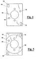
- such first flange 10 provides a couple of holes 12, substantially rectangular, suitable for allowing the passage of enlarged ends 22 which are integral to pins 23 pivotally connected to second flange 20 and which are also substantially rectangular.
- Pins 23 have levers 24 that allow their rotation about axes 23a.
- the coupling steps for making first flange 10 integral to second flange 20, as better shown in figures 2 and 3, as well as in figures 6 and 7, comprises the arranging of enlarged ends 22 in an angular position with respect to axis of pins 23 in which both enlarged ends 22 can pass through holes 12, crossing them completely and protruding beyond first flange 10. Then, the rotation of pins 23, by means of levers 24, from the first to the second angular position causes the rotation of enlarged ends 22 whereby these cannot be any more extracted back through holes 12, which do not have a circular shape.
- knobs 24 can be in an easier way provided for, which may comprise visual elements on their surface, for example portions of different colours, for indicating to the user the angular position of the enlarged ends 22.
- pins 23 comprises click means 15 that indicate to the operator when enlarged ends 22 are rotated to the second position.
- click means 15 preferably comprise a spring loaded ball pushed against pins 23 and suitable for engaging in a recess 25, corresponding to the locking position of enlarged end 22. Furthermore, the spring loaded ball prevents pin 23 from rotating accidentally in the first position owing to possible vibrations.
- centring means for a precise coupling between first flange 10 and second flange 20 many centring means of known type can be provided.
- centring means comprises two asymmetrical dowels 26 in second flange 20 that engage with corresponding holes 16 provided in first flange 10.
- first flange 10 can be executed in order to be mounted on support 5 whereas second flange 20 can be executed in order to be mounted on shroud 1.
- pins 23 with enlarged ends 22 can be executed on the removable part that comprises shroud 1
- slotted holes 12 can be executed on the fixed part, integral to support 5.
- first flange 10 provides a central hole 18 for the passage of a hook cover device 19.
- second flange 20 provides a central hole 28 and a cylindrical enlargement 29 for the connection to support 5 and for the partial housing of bearing 6 and of shaft 4.
- shroud 1 has a back bracket 9 for the height adjusting with respect to first flange 10.
Landscapes
- Engineering & Computer Science (AREA)
- Manufacturing & Machinery (AREA)
- Power Engineering (AREA)
- Auxiliary Devices For And Details Of Packaging Control (AREA)
- Basic Packing Technique (AREA)
- Insulation, Fastening Of Motor, Generator Windings (AREA)
- Manufacture Of Motors, Generators (AREA)
Applications Claiming Priority (2)
| Application Number | Priority Date | Filing Date | Title |
|---|---|---|---|
| IT1998PI000033A IT1306118B1 (it) | 1998-04-28 | 1998-04-28 | Dispositivo per il cambio rapido delle ganasce guidafilo in unamacchina avvolgitrice di indotti |
| ITPI980033 | 1998-04-28 |
Publications (1)
| Publication Number | Publication Date |
|---|---|
| EP0954084A1 true EP0954084A1 (fr) | 1999-11-03 |
Family
ID=11394259
Family Applications (1)
| Application Number | Title | Priority Date | Filing Date |
|---|---|---|---|
| EP99104362A Withdrawn EP0954084A1 (fr) | 1998-04-28 | 1999-03-04 | Dispositif pour le changement rapide des gabarits de bobinage dans les machines à bobiner les rotors |
Country Status (2)
| Country | Link |
|---|---|
| EP (1) | EP0954084A1 (fr) |
| IT (1) | IT1306118B1 (fr) |
Cited By (1)
| Publication number | Priority date | Publication date | Assignee | Title |
|---|---|---|---|---|
| ITFI20080162A1 (it) * | 2008-09-02 | 2010-03-03 | Team S R L | Dispositivo per il cambio rapido delle ganasce guidafilo in una macchina per l'avvolgimento di rotori per macchine elettriche quali motori e generatori elettrici. |
Citations (8)
| Publication number | Priority date | Publication date | Assignee | Title |
|---|---|---|---|---|
| US2144477A (en) * | 1937-09-28 | 1939-01-17 | Abrams Ralph | Armature winding machine |
| US3361371A (en) * | 1965-01-28 | 1968-01-02 | Globe Tool Eng Co | Armature winding machine |
| DE3347884A1 (de) * | 1982-09-08 | 1985-11-07 | Ncr Corp., Dayton, Ohio | Befestigungsvorrichtung zum entfernbaren befestigen zweier werkstuecke miteinander |
| US4765551A (en) * | 1985-11-19 | 1988-08-23 | Statomat-Globe, Inc. | Winding form |
| US4974313A (en) * | 1989-09-21 | 1990-12-04 | Odawara Automation, Inc. | Lead guide actuator mechanism for use on armature winding machines |
| US5064128A (en) * | 1989-02-03 | 1991-11-12 | Asmo Co., Ltd. | Wire guiding apparatus in coil winding machine |
| EP0484766A2 (fr) * | 1990-11-09 | 1992-05-13 | AXIS S.p.A. | Appareil pour faciliter le changement des enveloppes dans les machines à bobiner les rotors |
| US5123795A (en) * | 1990-08-29 | 1992-06-23 | Donaldson Company, Inc. | Quarter turn fastener |
-
1998
- 1998-04-28 IT IT1998PI000033A patent/IT1306118B1/it active
-
1999
- 1999-03-04 EP EP99104362A patent/EP0954084A1/fr not_active Withdrawn
Patent Citations (8)
| Publication number | Priority date | Publication date | Assignee | Title |
|---|---|---|---|---|
| US2144477A (en) * | 1937-09-28 | 1939-01-17 | Abrams Ralph | Armature winding machine |
| US3361371A (en) * | 1965-01-28 | 1968-01-02 | Globe Tool Eng Co | Armature winding machine |
| DE3347884A1 (de) * | 1982-09-08 | 1985-11-07 | Ncr Corp., Dayton, Ohio | Befestigungsvorrichtung zum entfernbaren befestigen zweier werkstuecke miteinander |
| US4765551A (en) * | 1985-11-19 | 1988-08-23 | Statomat-Globe, Inc. | Winding form |
| US5064128A (en) * | 1989-02-03 | 1991-11-12 | Asmo Co., Ltd. | Wire guiding apparatus in coil winding machine |
| US4974313A (en) * | 1989-09-21 | 1990-12-04 | Odawara Automation, Inc. | Lead guide actuator mechanism for use on armature winding machines |
| US5123795A (en) * | 1990-08-29 | 1992-06-23 | Donaldson Company, Inc. | Quarter turn fastener |
| EP0484766A2 (fr) * | 1990-11-09 | 1992-05-13 | AXIS S.p.A. | Appareil pour faciliter le changement des enveloppes dans les machines à bobiner les rotors |
Cited By (2)
| Publication number | Priority date | Publication date | Assignee | Title |
|---|---|---|---|---|
| ITFI20080162A1 (it) * | 2008-09-02 | 2010-03-03 | Team S R L | Dispositivo per il cambio rapido delle ganasce guidafilo in una macchina per l'avvolgimento di rotori per macchine elettriche quali motori e generatori elettrici. |
| WO2010026610A1 (fr) * | 2008-09-02 | 2010-03-11 | Team S.R.L.. | Dispositif de changement rapide des mâchoires de guide-fil dans une machine à bobiner des induits pour machines électriques |
Also Published As
| Publication number | Publication date |
|---|---|
| ITPI980033A1 (it) | 1999-10-28 |
| ITPI980033A0 (it) | 1998-04-28 |
| IT1306118B1 (it) | 2001-05-29 |
Similar Documents
| Publication | Publication Date | Title |
|---|---|---|
| EP1156142B1 (fr) | Rotor de filage à bout libre | |
| US6217248B1 (en) | Quick-change winding form assembly | |
| US20110163628A1 (en) | Pin-style collector brush holder with rotating spring plate, radial contact, and brush-wear indicator | |
| US8618713B2 (en) | Brush holder apparatus | |
| DE19853330A1 (de) | Miniatur-Wärmeableitgebläseanordnung | |
| DE102020131302A1 (de) | Kraftwerkzeug | |
| JPH04232879A (ja) | ケーブルピボットを備えた電子装置試験システム | |
| EP0954084A1 (fr) | Dispositif pour le changement rapide des gabarits de bobinage dans les machines à bobiner les rotors | |
| EP1895277B1 (fr) | Codeur rotatif avec aide de montage | |
| EP0875979B1 (fr) | Moteur électrique avec une fixation pour l'enroulement de stator | |
| CN219871922U (zh) | 一种物镜切换装置 | |
| EP1183416A1 (fr) | Dispositif d'entrainement pour machine a laver | |
| CZ20013299A3 (cs) | Dopřádací zařízení | |
| DE29901967U1 (de) | Elektromotor mit einer Anordnung zur Drehzahlüberwachung | |
| US6349895B1 (en) | Changeable flyer | |
| DE19820464A1 (de) | Elektrischer Schwenkmotor, insbesondere für eine Textilmaschine | |
| KR950004988B1 (ko) | 전기연결장치 | |
| US2817723A (en) | Electrical switch mountings | |
| DE2824183A1 (de) | Vorrichtung zum messen von drehmomenten | |
| EP0425040A2 (fr) | Appareil pour accoupler un ventilateur à son arbre d'entraînement, particulièrement dans les fours électriques du type ménager | |
| WO2001027374A1 (fr) | Machine a coudre a moteur electrique comportant une roue de d'aerateur et un capteur de vitesse | |
| GB2202383A (en) | Magnet alignment in a PMDC motor | |
| US4955251A (en) | Adjusting device for the pointer element of a drive range indicating display | |
| US3524420A (en) | Yarn separating device for sewing machines | |
| CN223141329U (zh) | 用于开关柜的摇把装置 |
Legal Events
| Date | Code | Title | Description |
|---|---|---|---|
| PUAI | Public reference made under article 153(3) epc to a published international application that has entered the european phase |
Free format text: ORIGINAL CODE: 0009012 |
|
| AK | Designated contracting states |
Kind code of ref document: A1 Designated state(s): AT CH DE DK ES FR GB IE IT LI NL PT SE |
|
| AX | Request for extension of the european patent |
Free format text: AL;LT;LV;MK;RO;SI |
|
| AKX | Designation fees paid | ||
| REG | Reference to a national code |
Ref country code: DE Ref legal event code: 8566 |
|
| 17P | Request for examination filed |
Effective date: 20000705 |
|
| RAX | Requested extension states of the european patent have changed |
Free format text: SI PAYMENT 20000705 |
|
| RBV | Designated contracting states (corrected) |
Designated state(s): AT CH DE DK ES FR GB IE IT LI NL PT SE |
|
| 17Q | First examination report despatched |
Effective date: 20040827 |
|
| STAA | Information on the status of an ep patent application or granted ep patent |
Free format text: STATUS: THE APPLICATION IS DEEMED TO BE WITHDRAWN |
|
| 18D | Application deemed to be withdrawn |
Effective date: 20050307 |