EP0954099A2 - Interrupteur à pression - Google Patents
Interrupteur à pression Download PDFInfo
- Publication number
- EP0954099A2 EP0954099A2 EP99100218A EP99100218A EP0954099A2 EP 0954099 A2 EP0954099 A2 EP 0954099A2 EP 99100218 A EP99100218 A EP 99100218A EP 99100218 A EP99100218 A EP 99100218A EP 0954099 A2 EP0954099 A2 EP 0954099A2
- Authority
- EP
- European Patent Office
- Prior art keywords
- pressure switch
- pressure
- switching element
- piston
- switch according
- Prior art date
- Legal status (The legal status is an assumption and is not a legal conclusion. Google has not performed a legal analysis and makes no representation as to the accuracy of the status listed.)
- Granted
Links
Images
Classifications
-
- H—ELECTRICITY
- H03—ELECTRONIC CIRCUITRY
- H03K—PULSE TECHNIQUE
- H03K17/00—Electronic switching or gating, i.e. not by contact-making and –breaking
- H03K17/94—Electronic switching or gating, i.e. not by contact-making and –breaking characterised by the way in which the control signals are generated
- H03K17/945—Proximity switches
- H03K17/95—Proximity switches using a magnetic detector
- H03K17/9505—Constructional details
Definitions
- the invention is based on a pressure switch the genus of claim 1.
- Be pressure switches for example for the control of pressure fluid operated Systems used and have a housing with a cylinder in which a pressurizable piston can be moved is led. The piston movement is controlled by a switching element converted into an electrical signal. It is known for this mechanical or non-contact electronic ones To use switching elements.
- non-contact electronic Switching elements have the disadvantage that they consist of a variety of separately arranged individual components, such as Sensor, evaluation electronics etc. are made by cables need to be connected. For contacting are usually expensive to manufacture and prone to failure Soldering used. It can be done by confusing the Cables make incorrect connections. It is also for such Cable connections in the pressure switch have a relatively large amount of installation space required. Often there is also a cost-causing positional and positional arrangement of the individual parts necessary for a reliable switch function ensure. Furthermore, the hydraulic Components of the pressure switch for interaction with a contactless sensor on this be coordinated. This is complex and also space-intensive.
- a pressure switch with the characteristic Features of claim 1 have the advantage of being Switching element a pre-assembled, i.e. of the hydraulic components detached, mechanically Actuatable single component that is contactless switches on and without soldering connections to one from the outside a pressure switch attachable device plug can be integrated is.
- This connector is therefore in case of repair easy to replace and requires almost no one Adjustment or adjustment effort. This is achieved through the Use of a magnetic field sensitive sensor in one Switching element that is associated with plug contacts Reliable contacts inside the connector is electrically coupled.
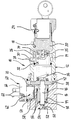
- the pressure switch 10 shown has a housing 12 which exemplary consists of a base body 14 which in one cuboid control block 16 used pressure-tight and is then caulked.
- the base body 14 forms a cylindrical hollow profile, which at its 16 opposite end has an internal thread 18.
- An adjusting spindle 20 is screwed into the internal thread 18.
- the adjusting spindle 20 is facing outward End face with a for assembly and adjustment reasons Device 24 provided to avoid unintentional operations can be locked.
- the adjusting spindle 20 is provided with a recess 26 in the one in the assembled state one in a radial Threaded bore 28 of the base body 14 arranged Grub screw 30 engages around the adjusting spindle 20 to be fixed in place on the base body 14.
- the adjusting spindle 20 has a center arranged, blind hole-shaped recess 32.
- a spring plate 34 for guidance a compression spring 36.
- This spring plate 34 is hat-shaped trained and points in its open to the outside centric recess two laterally from the wall of the Spring plate guided, axially one behind the other balls 35 on.
- One of the two balls 35 protrudes over the edge of the Spring plates 34 and is supported on the bottom of the Recess 32 from. This is in operative connection with the Compression spring 36 is an inclined position of the spring plate 34 largely avoided.
- the end of the compression spring 36 facing away from the spring plate 34 is located on an indexing plate 38.
- This switch plate 38 is axially movable in a chamber 42 which is between the base body 14 and the screwed Control block 16 results.
- the control block 16 is with a provided multiple offset through hole 44.
- a centrally arranged piston 46 pressed in On its side facing the control block 16 is in the Switch plate 38 a centrally arranged piston 46 pressed in.
- the latter is in a sleeve-shaped Valve insert 48 which in the through bore 44 of the Control block 16 is fixed, axially movable.
- the Piston 46 is a solid, rotationally symmetrical Component with two identically designed ends and can thus be attached to the switch plate 38 regardless of position. Both ends of the piston 46 are to simplify the Joining process with the indexing plate 38 with chamfers Mistake. With its free end, the piston 46 protrudes beyond the Valve insert 48 and ends in a pressure chamber 50.
- This pressure chamber 50 is via an inlet 52 and an after externally sealed connection 54 with pressure medium actable.
- valve insert 48 on both its outer and inner circumference Provide sealing bodies 56.
- the connector 60 is structured into a collar projecting into the receiving opening 58 64 and one piece connected to the collar 64, external mounting base 66. Due to the Shaping, for example by circumferentially formed Flattenings on the receiving opening 58 or the outer contour of federal 64, both components are in position and arranged against rotation.
- the mounting base 66 projects beyond the collar 64 on all sides and points outwards pointing contacts 68 for making electrical contact Switching element 62, which in a from the collar 64 of the Device connector 60 is arranged enclosed interior.
- the switching element 62 consists essentially of one known in the art, magnetic field sensitive Sensor, for example a Hall switch Sensor and an associated evaluation electronics, wherein both components by not shown plug contacts conductive with the inner ends of the contacts 68 of the Device connector 60 are connected.
- the housing of the Device connector 60 is made of plastic, preferably in one Injection molding process made - its metallic contacts 68 are at least partially as inserts in this Injectable housing.
- Pressure switch 10 is assumed that the Pressure chamber 50 is supplied with pressure medium. Because of the The piston 46 experiences a first pressure in the pressure medium Axial force in the direction of the base body 14. This first Axial force is exerted by the prestress of the compression spring 36 dependent second axial force counter. If the pressure exceeds in the pressure medium one of this bias of the compression spring 36 determined pressure threshold, the piston 46 moves or the switching plate 38 coupled to it in the direction of Base body 14 until the first axial force and second axial force are in equilibrium again, or until the switching plate 38 at its housing end stop is present.
- the spring-loaded actuating plunger 70 follows the movement of the indexing plate 38 and, if necessary, triggers Switching element 62 a switching process, which the described change in the voltage relationships on its Contacts 68 causes.
- the changed tension can by an external and with the pressure switch 10 through Control connected to signal lines be evaluated.
- the described mechanical actuation of the switching element 62 allows this as a functional pre-assembled Manufacture unit, in a simple plug-in operation to install in the interior of a connector 60 and to contact electrically.
- This connector 60 can be used as Subsequent assembly from the outside, i.e. accessible by the operator, be attached to the pressure switch 10.
- This structure allows to take advantage of a non-contact Switching element 62 with those of a mechanical actuation to combine the same without additional assembly or Adjustment effort arises. Constructive adjustments to the hydraulic components of the pressure switch 10 to the Operation of the switching element 62 is not necessary - An optimization of these components with regard to their hydraulic Function is possible.
Landscapes
- Switches Operated By Changes In Physical Conditions (AREA)
- Measuring Fluid Pressure (AREA)
Applications Claiming Priority (2)
| Application Number | Priority Date | Filing Date | Title |
|---|---|---|---|
| DE19818841 | 1998-04-28 | ||
| DE1998118841 DE19818841A1 (de) | 1998-04-28 | 1998-04-28 | Druckschalter |
Publications (3)
| Publication Number | Publication Date |
|---|---|
| EP0954099A2 true EP0954099A2 (fr) | 1999-11-03 |
| EP0954099A3 EP0954099A3 (fr) | 1999-12-01 |
| EP0954099B1 EP0954099B1 (fr) | 2006-06-14 |
Family
ID=7865971
Family Applications (1)
| Application Number | Title | Priority Date | Filing Date |
|---|---|---|---|
| EP99100218A Expired - Lifetime EP0954099B1 (fr) | 1998-04-28 | 1999-01-08 | Interrupteur à pression |
Country Status (2)
| Country | Link |
|---|---|
| EP (1) | EP0954099B1 (fr) |
| DE (2) | DE19818841A1 (fr) |
Families Citing this family (2)
| Publication number | Priority date | Publication date | Assignee | Title |
|---|---|---|---|---|
| DE10042011C1 (de) * | 2000-08-26 | 2002-06-27 | Bosch Gmbh Robert | Druckschalter |
| DE102005049171A1 (de) * | 2005-10-14 | 2007-04-19 | Bosch Rexroth Ag | Hydraulischer Druckschalter |
Family Cites Families (10)
| Publication number | Priority date | Publication date | Assignee | Title |
|---|---|---|---|---|
| DE2640529C3 (de) * | 1976-09-09 | 1979-03-15 | Purolator Filter Gmbh, 7110 Oehringen | Differenzdruckanzeigevorrichtung |
| DE2813692A1 (de) * | 1978-03-30 | 1979-10-11 | Rafi Gmbh & Co | Drucktaster |
| DE3505772A1 (de) * | 1985-02-20 | 1986-08-21 | rsn Maschinenbau GmbH, 7910 Neu-Ulm | Hydraulische brikettpresse mit schalteinrichtung |
| US5034621A (en) * | 1987-12-16 | 1991-07-23 | Eaton Corporation | Inductive proximity switch exhibiting magnetic field immunity |
| DE4141162A1 (de) * | 1991-12-13 | 1993-06-17 | Turck Werner Kg | Befestigungsklemme zur anbringung von naeherungssensoren an druckmittelzylindern |
| EP0620647A3 (fr) * | 1993-04-14 | 1995-09-06 | Namco Controls Corp | Commutateur de proximité magnétique. |
| DE9307564U1 (de) * | 1993-05-18 | 1993-10-07 | Honsberg & Co KG, 42897 Remscheid | Durchflußschalter |
| DE4333098A1 (de) * | 1993-09-29 | 1995-01-19 | Bosch Gmbh Robert | Druckschalter für Hydroeinheiten |
| JPH097477A (ja) * | 1995-06-22 | 1997-01-10 | Aisin Seiki Co Ltd | 圧力スイッチ |
| JPH0992104A (ja) * | 1995-09-26 | 1997-04-04 | Aisin Seiki Co Ltd | 圧力スイッチ |
-
1998
- 1998-04-28 DE DE1998118841 patent/DE19818841A1/de not_active Withdrawn
-
1999
- 1999-01-08 EP EP99100218A patent/EP0954099B1/fr not_active Expired - Lifetime
- 1999-01-08 DE DE59913539T patent/DE59913539D1/de not_active Expired - Lifetime
Also Published As
| Publication number | Publication date |
|---|---|
| EP0954099B1 (fr) | 2006-06-14 |
| EP0954099A3 (fr) | 1999-12-01 |
| DE19818841A1 (de) | 1999-11-11 |
| DE59913539D1 (de) | 2006-07-27 |
Similar Documents
| Publication | Publication Date | Title |
|---|---|---|
| DE102012212525A1 (de) | Hauptbremszylinder mit einer Vorrichtung zur berührungslosen Überwachung von Position und Bewegung eines linear bewegbaren Kolbens | |
| DE102018003752B4 (de) | Parksperrenmodul zur Betätigung einer Parksperre in einem Kraftfahrzeug | |
| DE102016222242B4 (de) | Ventilanordnung und damit ausgestattete fluidbetätigte Stellvorrichtung | |
| DE102008020934A1 (de) | Hauptbremszylinderanordnung mit Betätigungserfassung für eine Kraftfahrzeugbremsanlage und Kraftfahrzeugbremsanlage | |
| EP3683479A1 (fr) | Système de réglage pour une soupape | |
| EP1852587B1 (fr) | Régulateur de pression de suralimentation pour turbocompresseur de moteurs à combustion interne pour automobile | |
| DE102009041159A1 (de) | Wegsensoreinheit und Ventilanordnung | |
| DE102016014483A1 (de) | Hauptbremszylinderanordnung mit Positionsgeberelement und Kopplungsanordnung hierfür | |
| DE202015102487U1 (de) | Schalteinrichtung zum Schalten eines Mehrkupplungsgetriebes | |
| EP1852586B1 (fr) | Régulateur de pression de suralimentation pour turbosoufflante et turbocompresseur de moteurs à combustion interne pour automobile | |
| DE102012109094A1 (de) | Regelventilvorrichtung für einen Hydraulikkreislauf sowie Verfahren zur Regelung des Förderdrucks einer variablen Ölpumpe | |
| DE102011116632A1 (de) | Ventil, hydraulische Anordnung mit einem derartigen Ventil und Verwendung eines Tasters oder Schalters für ein Ventil | |
| DE102012022520A1 (de) | Hauptbremszylinderanordnung mit Betätigungserfassung für eine Kraftfahrzeugbremsanlage | |
| EP0954099B1 (fr) | Interrupteur à pression | |
| EP0487938B1 (fr) | Servofrein à vide | |
| WO2009080632A1 (fr) | Dispositif et procédé de réglage et/ou de contrôle d'un signal de sortie d'élément de détection dans une zone fonctionnelle d'un détecteur | |
| EP3155280A1 (fr) | Maître-cylindre destiné à un système de débrayage | |
| DE20106298U1 (de) | Linearantrieb | |
| EP1361325A1 (fr) | Actionneur pour fermetures des vehicules | |
| DE102011118519B4 (de) | Fluidbetätigter Linearantrieb | |
| DE102006050525A1 (de) | Wegmesssystem für Kupplungsausrücksysteme | |
| EP0954000A2 (fr) | Interrupteur à pression | |
| DE202013100461U1 (de) | Mikroschalter für einen Druckschalter mit einstellbarer Hysterese und Druckschalter mit derartigem Mikroschalter | |
| DE102019108261A1 (de) | Druckschaltvorrichtung | |
| AT503996B1 (de) | Hydraulischer druckschalter |
Legal Events
| Date | Code | Title | Description |
|---|---|---|---|
| PUAI | Public reference made under article 153(3) epc to a published international application that has entered the european phase |
Free format text: ORIGINAL CODE: 0009012 |
|
| PUAL | Search report despatched |
Free format text: ORIGINAL CODE: 0009013 |
|
| AK | Designated contracting states |
Kind code of ref document: A2 Designated state(s): DE FR GB IT |
|
| AX | Request for extension of the european patent |
Free format text: AL;LT;LV;MK;RO;SI |
|
| AK | Designated contracting states |
Kind code of ref document: A3 Designated state(s): AT BE CH CY DE DK ES FI FR GB GR IE IT LI LU MC NL PT SE |
|
| AX | Request for extension of the european patent |
Free format text: AL;LT;LV;MK;RO;SI |
|
| RIC1 | Information provided on ipc code assigned before grant |
Free format text: 6H 03K 17/97 A, 6H 03K 17/95 B |
|
| 17P | Request for examination filed |
Effective date: 20000602 |
|
| AKX | Designation fees paid |
Free format text: DE FR GB IT |
|
| 17Q | First examination report despatched |
Effective date: 20041008 |
|
| GRAP | Despatch of communication of intention to grant a patent |
Free format text: ORIGINAL CODE: EPIDOSNIGR1 |
|
| GRAS | Grant fee paid |
Free format text: ORIGINAL CODE: EPIDOSNIGR3 |
|
| GRAA | (expected) grant |
Free format text: ORIGINAL CODE: 0009210 |
|
| AK | Designated contracting states |
Kind code of ref document: B1 Designated state(s): DE FR GB IT |
|
| PG25 | Lapsed in a contracting state [announced via postgrant information from national office to epo] |
Ref country code: IT Free format text: LAPSE BECAUSE OF FAILURE TO SUBMIT A TRANSLATION OF THE DESCRIPTION OR TO PAY THE FEE WITHIN THE PRESCRIBED TIME-LIMIT;WARNING: LAPSES OF ITALIAN PATENTS WITH EFFECTIVE DATE BEFORE 2007 MAY HAVE OCCURRED AT ANY TIME BEFORE 2007. THE CORRECT EFFECTIVE DATE MAY BE DIFFERENT FROM THE ONE RECORDED. Effective date: 20060614 Ref country code: GB Free format text: LAPSE BECAUSE OF FAILURE TO SUBMIT A TRANSLATION OF THE DESCRIPTION OR TO PAY THE FEE WITHIN THE PRESCRIBED TIME-LIMIT Effective date: 20060614 |
|
| REG | Reference to a national code |
Ref country code: GB Ref legal event code: FG4D Free format text: NOT ENGLISH |
|
| REF | Corresponds to: |
Ref document number: 59913539 Country of ref document: DE Date of ref document: 20060727 Kind code of ref document: P |
|
| GBV | Gb: ep patent (uk) treated as always having been void in accordance with gb section 77(7)/1977 [no translation filed] |
Effective date: 20060614 |
|
| PLBE | No opposition filed within time limit |
Free format text: ORIGINAL CODE: 0009261 |
|
| STAA | Information on the status of an ep patent application or granted ep patent |
Free format text: STATUS: NO OPPOSITION FILED WITHIN TIME LIMIT |
|
| EN | Fr: translation not filed | ||
| 26N | No opposition filed |
Effective date: 20070315 |
|
| PG25 | Lapsed in a contracting state [announced via postgrant information from national office to epo] |
Ref country code: FR Free format text: LAPSE BECAUSE OF FAILURE TO SUBMIT A TRANSLATION OF THE DESCRIPTION OR TO PAY THE FEE WITHIN THE PRESCRIBED TIME-LIMIT Effective date: 20070309 |
|
| PG25 | Lapsed in a contracting state [announced via postgrant information from national office to epo] |
Ref country code: FR Free format text: LAPSE BECAUSE OF FAILURE TO SUBMIT A TRANSLATION OF THE DESCRIPTION OR TO PAY THE FEE WITHIN THE PRESCRIBED TIME-LIMIT Effective date: 20060614 |
|
| PGFP | Annual fee paid to national office [announced via postgrant information from national office to epo] |
Ref country code: DE Payment date: 20120327 Year of fee payment: 14 |
|
| PGFP | Annual fee paid to national office [announced via postgrant information from national office to epo] |
Ref country code: IT Payment date: 20120124 Year of fee payment: 14 |
|
| PG25 | Lapsed in a contracting state [announced via postgrant information from national office to epo] |
Ref country code: DE Free format text: LAPSE BECAUSE OF NON-PAYMENT OF DUE FEES Effective date: 20130801 |
|
| REG | Reference to a national code |
Ref country code: DE Ref legal event code: R119 Ref document number: 59913539 Country of ref document: DE Effective date: 20130801 |
|
| PG25 | Lapsed in a contracting state [announced via postgrant information from national office to epo] |
Ref country code: IT Free format text: LAPSE BECAUSE OF NON-PAYMENT OF DUE FEES Effective date: 20130108 |