EP0954500B1 - Transportwagen für ein gütertransport-förderungsystem - Google Patents
Transportwagen für ein gütertransport-förderungsystem Download PDFInfo
- Publication number
- EP0954500B1 EP0954500B1 EP96932957A EP96932957A EP0954500B1 EP 0954500 B1 EP0954500 B1 EP 0954500B1 EP 96932957 A EP96932957 A EP 96932957A EP 96932957 A EP96932957 A EP 96932957A EP 0954500 B1 EP0954500 B1 EP 0954500B1
- Authority
- EP
- European Patent Office
- Prior art keywords
- material handling
- handling system
- cpu
- tray
- load support
- Prior art date
- Legal status (The legal status is an assumption and is not a legal conclusion. Google has not performed a legal analysis and makes no representation as to the accuracy of the status listed.)
- Expired - Lifetime
Links
- 230000003137 locomotive effect Effects 0.000 claims abstract description 36
- 238000004891 communication Methods 0.000 claims abstract description 6
- 101000606504 Drosophila melanogaster Tyrosine-protein kinase-like otk Proteins 0.000 claims abstract description 5
- 230000004044 response Effects 0.000 claims description 11
- 238000007599 discharging Methods 0.000 claims description 4
- 230000005540 biological transmission Effects 0.000 abstract description 2
- 230000007246 mechanism Effects 0.000 description 17
- 230000005355 Hall effect Effects 0.000 description 4
- 238000013459 approach Methods 0.000 description 4
- 230000006872 improvement Effects 0.000 description 4
- 230000007935 neutral effect Effects 0.000 description 4
- 230000001419 dependent effect Effects 0.000 description 2
- 238000010586 diagram Methods 0.000 description 2
- 238000012545 processing Methods 0.000 description 2
- 230000000712 assembly Effects 0.000 description 1
- 238000000429 assembly Methods 0.000 description 1
- 230000015572 biosynthetic process Effects 0.000 description 1
- 238000002716 delivery method Methods 0.000 description 1
- 238000011161 development Methods 0.000 description 1
- 230000006698 induction Effects 0.000 description 1
- 238000009434 installation Methods 0.000 description 1
- 230000007774 longterm Effects 0.000 description 1
- 238000012423 maintenance Methods 0.000 description 1
- 238000000034 method Methods 0.000 description 1
- 238000005192 partition Methods 0.000 description 1
- 230000008569 process Effects 0.000 description 1
Images


Classifications
-
- B—PERFORMING OPERATIONS; TRANSPORTING
- B61—RAILWAYS
- B61B—RAILWAY SYSTEMS; EQUIPMENT THEREFOR NOT OTHERWISE PROVIDED FOR
- B61B13/00—Other railway systems
- B61B13/04—Monorail systems
-
- B—PERFORMING OPERATIONS; TRANSPORTING
- B61—RAILWAYS
- B61C—LOCOMOTIVES; MOTOR RAILCARS
- B61C11/00—Locomotives or motor railcars characterised by the type of means applying the tractive effort; Arrangement or disposition of running gear other than normal driving wheel
- B61C11/04—Locomotives or motor railcars characterised by the type of means applying the tractive effort; Arrangement or disposition of running gear other than normal driving wheel tractive effort applied to racks
-
- B—PERFORMING OPERATIONS; TRANSPORTING
- B65—CONVEYING; PACKING; STORING; HANDLING THIN OR FILAMENTARY MATERIAL
- B65G—TRANSPORT OR STORAGE DEVICES, e.g. CONVEYORS FOR LOADING OR TIPPING, SHOP CONVEYOR SYSTEMS OR PNEUMATIC TUBE CONVEYORS
- B65G47/00—Article or material-handling devices associated with conveyors; Methods employing such devices
- B65G47/74—Feeding, transfer, or discharging devices of particular kinds or types
- B65G47/94—Devices for flexing or tilting travelling structures; Throw-off carriages
- B65G47/96—Devices for tilting links or platform
- B65G47/962—Devices for tilting links or platform tilting about an axis substantially parallel to the conveying direction
Definitions
- the invention is generally related to automated material handling systems utilizing one or more train-type guided vehicles transporting goods between induction and discharge stations in a sortation system.
- Automated material handling and sortation systems are known for receiving, transporting and discharging goods among various stations in large scale sortation operations such, for example, as warehousing, distribution, postal sortation and handling of mail and packages, and airport baggage handling. Whatever the operation, goods typically originate from one location within the facility and must be sorted and transported to several different locations for further handling, or originate from several locations within a facility and must be transported to a single location such as a shipping dock. The manner in which the various goods are stored and selectively distributed among various stations in a facility of course depends on the nature of the operation.
- One known sortation and delivery method involves using powered belt or roller conveyers to transport individual items or sorted loads of items to various destinations within a facility.
- powered belt or roller conveyers When goods from multiple sources must be delivered to a single station, associated take away conveyors must be merged onto a main conveyor or discharge point. This requires careful coordination of each item as it arrives to prevent jams or damage.
- US-A-5 018 928 is also disclosed a material handling system including:
- This invention is directed to the provision of an improved trolley car for a material handling train.
- this invention is directed to the provision of an improved material handling system incorporating the improved trolley car.
- the invention is further directed to the provision of an improved mechanism for moving the tiltable tray of a tray trolley between its various positions.
- a CPU is provided and sensor means are provided on each car which are operative to sense information with respect to the products on the load support surface of that car and transmit the sensed information to the CPU for storage and utilization by the CPU software in controlling the load support surface to facilitate the receipt, transport and discharge of the products.
- This arrangement enables each trolley car to utilize information sensed with respect to products on the load support surface of the car and use this information in the handling of the products.
- each trolley car includes a CPU and the information sensed with respect to the products on the load support surface of each car is transmitted to the CPU of that car. This arrangement allows each trolley car to both sense and process information with respect to products on the load support surface of the car.
- a further feature of the invention is disclosed in claim 3.
- This arrangement allows the CPU on board each trolley car to either use the sensed and stored information with respect to the products on the load support surface of that car directly in the control of the handling of these products and/or transmit this. information to the locomotive CPU for use by the locomotive CPU in controlling the product handling.
- a further feature is disclosed in claim 4.
- This arrangement provides a total control system in which the sensed information on each trolley may be utilized directly by the CPU of that trolley, may be transmitted to the locomotive CPU for use by the locomotive CPU in controlling the handling of the products, or may be transmitted by the locomotive CPU to the dispatch CPU for use by the dispatch CPU in controlling the overall handling of the products by the system.
- the communication between the locomotive CPU and the dispatch CPU is by radio frequency. This arrangement obviates the need for a hard wire connection between the locomotive CPU and the dispatch CPU.
- the information sensed by the sensor means includes a wide variety of information with respect to the product being handled including information with respect to the disposition of the load support surface; information with respect to the presence or absence of a product load on the load support surface; information with respect to the size, position or orientation of a product load on the load support surface; information with respect to the weight of a product load on the load support surface; information with respect to the identification of a product load on the load support surface; or information with respect to the temperature of a product load on the load support surface.
- the load support surface is defined by a tiltable tray and each trolley car includes a pivot shaft which rotates in response to tilting movement of the tray and the sensor means for detecting the position of the tray includes signal means operative to sense the angular position of the pivot shaft and thereby generate a tray position signal corresponding to the angular position of the pivot shaft.
- the signal means comprises at least one magnetic member positioned on the pivot shaft and at least one switch member associated with the magnetic member and operative to sense the presence or absence of the magnetic member and thereby generate a present/absent digital signal representative of the angular position of the pivot shaft and thereby representative of the angular position of the tray.
- a further feature of the invention is disclosed in claim 19. This arrangement provides a simple and effective means for moving the tray between its various positions.
- a further feature of the invention is disclosed in claim 20.
- This arrangement provides a simple and effective means of moving the cam followers into and out of operative relation to the respective tracks.
- the shift means further includes latching means operative to latch the tray in its transport position upon arrival of the tray at its transport position and unlatching means operative to unlatch the tray as it begins its movement away from the transport position. This arrangement insures that the tray will not overshoot its transport position and yet may be moved readily to an inclined position.
- the latching means comprises a lug forming a part of the joint assembly coacting with a spring biased plunger structure to latch the lower end of the link structure and thereby the tray;
- the unlatching means comprises a pin and slot connection at the joint assembly;
- the pin has a circular cross-sectional configuration and the slot has a non-circular cross-sectional configuration defining diverging cam surfaces; and the pin coacts with a respective cam surface as the tray begins its movement away from the first or second inclined positions to pull the lug out of coaction with the plunger structure.
- the trolley car includes an indicator member movable between first and second positions in response to movement of the load support assembly of the trolley car between transport and discharge dispositions and signal means operative to sense the position of the indicator member and thereby of the load support assembly and generate a load support assembly disposition signal.
- the indicator means comprises a shaft pivotal between first and second angular positions in response to movement of the load support assembly between its transport and discharge dispositions and the signal means comprises at least one magnetic member positioned on the shaft and at least one switch member associated with the magnetic member and operative to sense the presence or absence of the magnetic member and thereby generate a presence/absent digital signal representative of the angular position of the shaft and thereby representative of the disposition of the load support assembly.
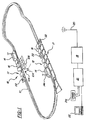
- the material handling system seen in the drawings includes a rail 10 arranged in a desired predetermined configuration such for example as the closed loop seen in Figure 1; one or more trains 12 arranged to run on the rail and each including a locomotive 14 pulling a plurality of trolley cars 16; at least one load station 17 and one unload station 18; a central dispatch CPU 19 located proximate but removed from the rail and communicating with a radio frequency transmitter/receiver 20; an information CPU 21 communicating with dispatch CPU 19 and including a printer 21a; and an input terminal 22.
- a rail 10 arranged in a desired predetermined configuration such for example as the closed loop seen in Figure 1
- one or more trains 12 arranged to run on the rail and each including a locomotive 14 pulling a plurality of trolley cars 16
- at least one load station 17 and one unload station 18 at least one load station 17 and one unload station 18
- a central dispatch CPU 19 located proximate but removed from the rail and communicating with a radio frequency transmitter/receiver 20
- an information CPU 21 communicating with dispatch CPU
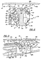
- Rail 10 may take various forms and may, as best seen in Figure 2, have an I configuration including a central upstanding web 10a; an upper triangular portion 10b defining a flat upper traction and support surface 10c and oppositely angled downwardly converging guide surfaces 10d; and a lower base portion 10e of triangular configuration including a lower support surface 10f and oppositely angled upwardly converging guide surfaces 10g.
- This invention relates to improvements in the trolley car 16 and in the manner in which the trolley cars are integrated with the total material handling system to improve the overall efficiency and versatility of the system.
- Each trolley car 16 includes a trolley 24 and a load support or tray assembly 26.
- Trolley 24 includes a yoke frame structure 28, lower guide wheels 30, upper guide wheels 32, support wheels 34, a printed circuit board 36, and a tray shift mechanism 38.
- Yoke frame structure 28 has an inverted U configuration and is arranged to be positioned in straddling relation over the rail.
- Lower guide wheels 30 are mounted in angled relation on lower flange portions 28a of the yoke frame structure with each wheel reliably engaging a respective lower rail guide surface 10g.
- Upper guide wheels 32 are mounted on upper flange members 28b of the yoke frame structure and reliably engage respective upper rail guide surfaces 10d.
- one centrally disposed lower guide wheel 30 may be provided at each side of the frame structure and two upper guide wheels 32 may be provided at each side of the frame structure.
- Support wheels 34 are journalled in a spine structure 28c formed along the top of the yoke frame structure and reliably engage rail surface 10c to support the trolley on the rail.
- a front and rear support wheel 34 are preferably provided.
- Printed circuit board 36 is positioned within a housing 28d forming a part of one side leg of the yoke frame structure and includes, inter alia, a CPU 44, an infrared transmitter 46, an infrared receiver 48, and related software.
- the free or operative ends of transmitter 46 and receiver 48 are positioned in suitable apertures in the outboard side wall 28e of housing 28d.
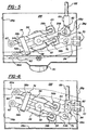
- Tray shift mechanism 38 ( Figures 4, 5, 6, and 7) is intended to selectively shift tray assembly 26 between a level, a left inclined, and a right inclined position so as to facilitate loading, transport, and discharge of products 22.
- Shift mechanism 38 includes a journal 50; a pivot shaft 52; a pivot arm 54; a pair of upper and lower follower arms 56, 58; a pair of upper and lower roller followers 60, 62 carried on the free ends of follower arms 56, 58; a pair of solenoids 64 mounted on the upper and lower ends of a cross bar 65 secured to pivot arm 54; a link 66; a link 68; and a latch mechanism 70 mounted on an end wall 28f of housing 28d.
- Journal 50 is mounted on the inboard face of a vertical partition 28f forming a part of yoke frame structure 28.
- Shaft 52 is journalled in journal 50 and extends inwardly from the journal.
- Pivot arm 54 is fixed to the inboard end of shaft 52 so as to turn with shaft 52 about a generally horizontal axis.
- Follower arms 56, 58 are mounted for pivotal movement about a vertical axis defined by a pin 72 passing through the follower arm and through pivot arm 54 and including a threaded central portion passing threadably through shaft 52.
- Cam follower 60 comprises a roller rollably mounted at one end 56a of follower arm 56 and cam follower 62 comprises a roller mounted on one end of follower arm 58.
- the plungers of solenoids 64 pivotally engage the other ends 56b, 58b of the follower arms so that the follower arms are pivoted about the axis of pins 72 in response to selective actuation of the respective solenoids with the extent of pivotal movement of the follower arm in each case being limited by a loop member 74 carried on one end 54a of arm 54.
- the other end 54b of arm 54 has a clevis formation ( Figure 7) including fork arm portions 54c.
- a pin 76 extends fixedly between fork portions 54b and a spring loaded pin 78 is mounted on the main body of pivot arm 54 and extends into the gap 80 between fork portions 54b.
- the lower end of link 66 includes a heart-shaped slot 82 through which pin 76 passes. Slot 82 defines a central rest portion 82a and diverging cam surfaces 82b, 82c. The lower end of link 66 further defines a lug 66a arranged for latching coaction with a pair of spring biased plungers 84 defined by latch mechanism 70.
- Link 68 is pivotally secured to the upper end of link 66 by a pin 86 and extends upwardly for connection to the tray assembly.
- Tray shift mechanism 38 is arranged for camming coaction with a cam plate 86 secured to a side face of the central web 10a of the track 10 and defining a pair of diverging tracks 86a and 86b for respective coaction with cam followers 60 and 62 to selectively shift the tray structure between level, left tilt, and right tilt positions.
- Load support or tray assembly 26 ( Figures 2, 3, and 8) includes a tray support 40 and a tray 42.
- Tray support 40 includes a main body support portion 40a and triangular flange portions 40b at each end of the support. Tray support 40 is pivotally mounted to trolley 24 by clevis pins 88 mounted at each end of the yoke frame spine structure 28c. The tray support is thus mounted for pivotal movement about a horizontal axis extending along the track.
- Tray 42 is suitably secured to the base 40a of tray support 40 and includes a flat floor 42a and front and rear upstanding flanges 42b.
- Floor 42a will be seen to define a load support surface for use in receiving, transporting, and discharging discrete products being handled by the material handling system.
- link 68 is suitably pivotally secured to a downstanding lug portion 40c of the tray support 40 so that upward and downward movement of the link 68 in response to actuation of tray shift mechanism 38 results in pivotal movement of the tray assembly 26 about the axis of clevis pins 88 between a relatively level or flat position, a left inclined position, and a right inclined position.
- the tilt position of the tray assembly is constantly sensed as a function of the position of pivot shaft 52 since pivot shaft 52 pivots in correspondence with the pivoting movement of the tray assembly.
- magnetic members 90 positioned at angularly spaced locations on a hub 92 secured to the free end of the shaft 52 coact with Hall Effect switches 94 which are suitably connected to circuit board 36 and which are suitably integrated into the circuitry of the circuit board.
- One magnetic member 90 is associated with each Hall Effect switch member 94 so that, as the shaft 52 rotates in response to shifting movement of the tray, the individual Hall Effect switch members 94 will constantly reflect the presence or absence of an associated magnetic member 90 and thereby generate a present/absent digital signal representative of the angular position of the shaft and thereby representative of the angular position of the tray assembly.
- a comparison of Figures 4, 5, and 6 shows the relative positioning of the Hall Effect switch members and the magnetic members as the tray assembly moves between its tilt positions.
- each tray assembly 26 may include one or more photo-eye transmitter assemblies 94a, 94b positioned along the respective flanges 42b of the tray; one or more load ID code readers 96 positioned along a flange of the tray; and one or more load temperature sensors 98 positioned along a flange of the tray.
- the photo-eye transmitters 94 function to detect the presence or absence of a product 22 on the tray and/or the size of the product (as a function of the number of photo-eye transmitters intercepted).
- Transmitters 94 also function to detect the orientation of the load, for proper processing, and detect movement of the load during transport.
- Load ID code readers 96 function to read the bar code or color code and thereby identify the particular product 22 positioned on the tray.
- Load temperature sensor 98 functions to determine the temperature of the product 22 positioned on the tray.
- the tray also desirably includes a sensor for determining the weight of the product 22 comprised, for example, of a load cell 100 positioned beneath the main body 42a of the tray so as to sense the added load of the product 22 as it is placed upon the tray.
- the information sensed or generated by the respective sensors is suitably transmitted to the circuit board 36 of the respective trolley car for processing and storage by CPU 44. These sensors in combination therefor provide to the CPU 44 information with respect to the presence of the product, the size of the product, the identity of the product, the temperature of the product, and the weight of the product.
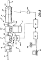
- the individual trolley cars 16 are interconnected for pulling purposes by links 102 extending between the front clevis 88 of one trolley car and the rear clevis 88 of the preceding car, and the successive cars are connected electrically by a cable 104 connected with the circuit board 36 of a respective car via a connector 106 positioned in the side wall 28g of the housing 28d containing the circuit board and extending forwardly therefrom for suitable connection to a similar connector 106 positioned in the side wall 28g of the housing 28d containing the circuit board of the preceding car.
- the circuit board 36 of each trolley car is suitably electrically connected to connectors 106 in the front and rear walls 28g of the respective housing 28d so that the circuit boards 36 are electrically connected in a continuous chain.
- Cables 104 are preferably routed through the links 102 which for that purpose have an inverted U-shaped configuration to provide a hollow through which the cables may be routed.
- the first car in the train is of course mechanically linked to the locomotive 14 and includes a cable 104 extending forwardly from that car for connection to the electrical system of the locomotive and specifically for connection to a CPU 107 positioned in the locomotive 14 and communicating by radio frequency via a locomotive antenna 14a with the transmitter/receiver 20 of dispatch CPU 19.
- the system may further include one or more local CPUs 108 positioned proximate the unload station 18 and arranged to communicate with the infrared receiver 48 of a specific trolley car 16 via an infrared transmitter 110.
- Local CPU 108 may, for example, utilize a photo cell assembly 112a, 112b positioned in association with a discharge chute 114 at the unload station to ascertain the full/not full status of the chute with respect to product capacity and relay this information via transmitter 110 and receiver 48 to an approaching trolley car 16.
- Local CPU 108 may also be connected to dispatch CPU 19 so as to receive further system information from the dispatch CPU for transmittal to each trolley car 16 via the transmitter 110 and receiver 48.
- Trains 12 desirably operate on a relatively continuous basis along the path determined by rail 10 to continuously pick up products 22 from load stations, transport the products to unload stations and discharge the products at the unload stations.
- trains proceed around the rail, they are controlled by a combination of information provided by dispatch CPU 19, locomotive CPU 107, local CPUs 108, and onboard circuit boards 36.
- the dispatch CPU dispatches information with respect to the scheduling of the cars, the content of the cars of each train and the destination of each train.
- sensors 94, 96, 98, and 100 operate to generate information with respect to the presence of the load, the size, position and orientation of the load, the identification of the load, the temperature of the load, and the weight of the load, and relay this information to the onboard computer 44.
- This information is stored in the onboard computer 44 and is also transmitted via the series of cables 104 to locomotive computer 107 where the information is stored and also communicated by radio frequency, utilizing antenna 14a and transmitter receiver 20, to dispatch CPU 19 for use by the dispatch CPU in controlling the overall operation of the system.
- the information provided to the onboard CPUs by the onboard sensors is also used onboard as a double check on commands received from the locomotive CPU. For example, if the locomotive CPU relays a command to a particular trolley car CPU ordering the tray of that car to tip right as the car approaches an unloading chute but the trolley car by virtue of its onboard information knows that it is not carrying a load, it will countermand the command from the locomotive. As a further example, if the locomotive provides a tip right command to the car as the car approaches an unloading chute but the local CPU 108 provides information to the receiver 48 of the car via infrared transmission that the chute is full, the car will again countermand the command from the locomotive CPU.
- the overall system thus has multiple redundancy in the sense that each trolley car can check on the commands given to it from the locomotive CPU by comparing these commands to information that has been sensed onboard by the onboard sensors and stored in the onboard CPU and can also check the commands from the locomotive CPU against information received from local CPUs at the unloading and/or loading stations.
- the system provides multiple fail-safe protection with the system constantly checking itself for error and making decisions only when the multiple items of information being received are in agreement.
- the tipping of the trays of the various trolley cars is controlled by the tray shift mechanism 38 on each car acting in coaction with a cam plate 86.
- a car carrying a product approaches an unloading chute on the right hand side of the car, and assuming that all of the redundant checks provided by the system indicate that the trolley is in fact carrying the proper cargo and that the chute has the capacity to receive the trolley cargo, an appropriate signal is sent by the locomotive CPU 107 to the appropriate solenoid 64 to actuate the solenoid in a sense to move the associated follower arm 56, 58 about the axis of pin 52 to move the associated cam follower roller 60, 62 into a position where it will engage the respective track 86a, 86b of the cam plate 86 as the trolley car approaches the unloading chute so that the shift mechanism may function to pivot the tray either to its left or its right inclined position, depending upon the location of the unloading chute, with the movement of the tray occurring as pivotal movement of the lever 54 and upward or downward movement of links 66, 68.
- the pin 76 occupies the bottom or left lobe portion 82a of the heart-shaped slot 82 by virtue of the spring bias pin 78 acting against the far end of link 64 and pushing the link to the right to move pin 76 into engagement with the left or bottom lobe of the heart-shaped slot.
- the suitable solenoid 60 When it is desired to move the tray to an inclined position, the suitable solenoid 60 is actuated and the initial portion of the angular movement of pivot arm 54 results in the pin 76 walking up or down a respective cam surface 82b or 82c defined by the cam shaped slot with the result that the link 66 and thereby the lug 66a is pulled to the left out of engagement with the plungers 84 to allow the shift mechanism to continue its movement to the desired inclined position, whereupon pin 76 will again assume a position seated in the left or bottom lobe portion 82a of the slot.
- the described arrangement thus ensures that the tray will be firmly latched in the neutral or level position and yet may be readily moved out of the latched configuration when the time comes to move the tray to a tilted position.
- the invention will be seen to provide an improved train-type material handling system in which each individual trolley car of the train has the onboard ability to receive and disseminate load and system information in a manner to improve the overall efficiency and effectiveness of the system as compared to train type systems in which the trolley cars are totally dependent on external sources for their status.
Landscapes
- Engineering & Computer Science (AREA)
- Mechanical Engineering (AREA)
- Transportation (AREA)
- Discharge Of Articles From Conveyors (AREA)
- Warehouses Or Storage Devices (AREA)
- Intermediate Stations On Conveyors (AREA)
- Control Of Position, Course, Altitude, Or Attitude Of Moving Bodies (AREA)
Claims (32)
- Materialtransportsystem mit:dadurch gekennzeichnet, daß es ferner aufweist:einer Schiene (10);einer Lokomotive (14), die zur motorisch betriebenen Bewegung längs der Schiene (10) angebracht ist;einem oder mehreren Fahrgestellwagen (16), die dazu eingerichtet sind, durch die Lokomotive längs der Schiene gezogen zu werden, und jeweils eine obere Lasttragefläche (10c, 10g) zur Verwendung bei der selektiven Aufnahme, Transport und Entladung diskreter Produkte bezüglich verschiedener Stationen längs der Schiene aufweisen;eine CPU (19,21,44) undeine Sensoreinrichtung (94,94a,94b,96,98,100,110) an jedem Wagen, die betriebsfähig ist, Informationen bezüglich der Produkte auf der Lasttragefläche jenes Wagens (16) abzutasten und die abgetasteten Informationen zur CPU zu senden, zur Speicherung und Nutzung durch die CPU-Software bei der Steuerung der Lasttragefläche in einer Weise, die die Aufnahme, den Transport und die Entladung der Produkte erleichtert.
- Materialtransportsystem nach Anspruch 1, wobei:jeder Fahrgestellwagen (16) eine CPU aufweist; unddie Information, die bezüglich des Produkts auf der Lasttragefläche (10c,10g) jedes Wagens abgetastet wird, an die CPU (19,21,44) jenes Wagens gesendet wird.
- Materialtransportsystem nach Anspruch 2, wobei:die Lokomotive eine CPU (107) aufweist; unddie abgetastete Information, die in jeder Fahrgestellwagen-CPU (108) gespeichert ist, zur Speicherung und Nutzung durch die Lokomotiven-CPU-Software bei der Aufnahme, beim Transport und bei der Entladung der Produkte zur Lokomotiven-CPU gesendet wird.
- Materialtransportsystem nach Anspruch 3, wobei:das System ferner eine zentrale Abfertigungs-CPU (19) aufweist, die außerhalb der Laufbahn angeordnet ist und den gesamten Betrieb des Materialtransportsystems steuert; unddie Lokomotiven-CPU (107) mit der Abfertigungs-CPU (19) kommuniziert und dazu dient, Informationen, die von der Fahrgestell-CPU empfangen werden, zur Nutzung durch die Abfertigungs-CPU bei der Steuerung des gesamten Betriebs des Materialtransportsystems zur Abfertigungs-CPU zu senden.
- Materialtransportsystem nach Anspruch 4, wobei die Kommunikation zwischen der Lokomotiven-CPU (107) und der Abfertigungs-CPU (19) durch Hochfrequenz stattfindet.
- Materialtransportsystem nach Anspruch 2, wobei das System ferner eine außerhalb der Laufbahn liegende CPU (19) und eine Einrichtung (14a,20,36) aufweist, die betriebsfähig ist, eine direkte Kommunikation zwischen der außerhalb der Laufbahn liegenden CPU und der Fahrgestellwagen-CPU (108) zuzulassen.
- Materialtransportsystem nach Anspruch 6, wobei die Einrichtung (14a,20,36), die eine Kommunikation zuläßt, eine Einrichtung (46,48,110) aufweist, die eine Infrarot-Kommunikation zwischen der außerhalb der Laufbahn liegenden CPU und der Fahrgestellwagen-CPU zuläßt.
- Materialtransportsystem nach Anspruch 1, wobei die Lasttragefläche (10c,10g) durch ein kippbares Tablett (42,50,54) definiert wird und die Information, die durch die Sensoreinrichtung (94,96,98,100) abgetastet wird, eine information bezüglich der Stellung des Tabletts umfaßt.
- Materialtransportsystem nach Anspruch 1, wobei die Information, die durch die Sensoreinrichtung abgetastet wird, eine Information bezüglich des Vorhandenseins oder Fehlens einer Produktlast (22) auf der Lasttragefläche umfaßt.
- Materialtransportsystem nach Anspruch 1, wobei die Information, die durch die Sensoreinrichtung (94,96,98,100) abgetastet wird, eine Information bezüglich der Größe, Position oder Orientierung einer Produktlast (22) auf der Lasttragefläche (10c,10g) umfaßt.
- Materialtransportsystem nach Anspruch 1, wobei die Information, die durch die Sensoreinrichtung abgetastet wird, eine Information bezüglich des Gewichts einer Produktlast (22) auf der Lasttragefläche (10c,10g) umfaßt.
- Materialtransportsystem nach Anspruch 1, wobei die Information, die durch die Sensoreinrichtung abgetastet wird, eine Information bezüglich der Identifizierung einer Produktlast (22) auf der Lasttragefläche (10c,10g) umfaßt.
- Materialtransportsystem nach Anspruch 1, wobei die Information, die durch die Sensoreinrichtung abgetastet wird, eine Information bezüglich der Temperatur einer Produktlast (22) auf der Lasttragefläche (10c,10g) umfaßt.
- Materialtransportsystem nach Anspruch 11, wobei die Sensoreinrichtung (94,96,98) ein Dehnungsmeßgerät aufweist, das nahe der Lasttragefläche (10c,10g) angeordnet ist.
- Materialtransportsystem nach Anspruch 8, wobei:jeder Fahrgestellwagen (16) eine Drehwelle (38,52) aufweist, die sich als Reaktion auf eine Kippbewegung des Tabletts dreht; unddie Sensoreinrichtung (94,96,98) eine Signaleinrichtung (90,94) aufweist, die betriebsfähig ist, die Winkelstellung der Drehwelle (52) abzutasten und dadurch ein Tablett-Stellungssignal zu erzeugen, das der Winkelstellung der Drehwelle entspricht.
- Materialtransportsystem nach Anspruch 15, wobei die Signaleinrichtung mindestens ein magnetisches Glied (90), das auf der Drehwelle (52) angeordnet ist, und mindestens ein Schaltglied (94) aufweist, das mit dem magnetischen Glied verbunden ist und betriebsfähig ist, das Vorhandensein oder Fehlen des magnetischen Gliedes abzutasten und dadurch ein Vorhanden/Fehlend-Digitalsignal zu erzeugen, das für die Winkelstellung der Drehwelle repräsentativ ist und dadurch für die Winkelstellung des Tabletts (42,50,54) repräsentativ ist.
- Materialtransportsystem nach Anspruch 9, wobei die Sensoreinrichtung einen Photozellenaufbau (94a,94b,112) aufweist, der an der Lasttragefläche (10c,10g) angeordnet ist.
- Materialtransportsystem nach Anspruch 12, wobei die Sensoreinrichtung einen Strichcode-Leser aufweist, der an der Lasttragefläche (10c,10g) angeordnet ist.
- Materialtransportsystem nach einem der vorhergehenden Ansprüche, wobei jeder Fahrgestellwagen (16) aufweist: ein Fahrgestell, das angepaßt ist, sich längs der Schiene (10) zu bewegen, und ein Tablett, das am Fahrgestell angebracht ist; und eine Umladeeinrichtung (38), die betriebsfähig ist, das Tablett zwischen einer im wesentlichen ebenen Transportstellung, einer ersten geneigten Entladestellung zur Entladung nach einer Seite der Schiene und einer zweiten entgegengesetzt geneigten Entladestellung zur Entladung zur anderen Seite der Schiene zu bewegen, dadurch gekennzeichnet, daß:die Umladeeinrichtung (38) aufweist: erste und zweite Mitnehmer-Laufbahnen, die längs der Schiene definiert sind, erste und zweite Mitnehmer-Kurvenrollen (60,62), die durch den Fahrgestellwagen getragen werden, und eine Einrichtung (64), die betriebsfähig ist, als Reaktion auf einen Eingriff der ersten Mitnehmer-Kurvenrolle in die erste Laufbahn (10,86a), das Tablett in die erste geneigte Entladestellung zu bewegen, und betriebsfähig ist, als Reaktion auf einen Eingriff der zweiten Mitnehmer-Kurvenrolle (62) in die zweite Laufbahn (10,86b) das Tablett in die zweite geneigte Entladestellung zu bewegen.
- Materialtransportsystem nach Anspruch 19, wobei die Umladeeinrichtung (38) erste und zweite Elektromagnete (64) aufweist, die durch das Fahrgestell (24) getragen werden und betriebsfähig sind, die ersten und zweiten Mitnehmer-Kurvenrollen (60,62) in eine Stellung hinein und aus ihr heraus zu bewegen, wo sie in eine jeweilige erste und zweite Laufbahn (86a,86b) eingreifen.
- Materialtransportsystem nach Anspruch 19, wobei die Umladeeinrichtung (38) ferner aufweist: einen Dreharm (54), der zur Drehbewegung um eine im wesentlichen horizontale Drehachse, die im wesentlichen normal zur Laufbahn ist, am Fahrgestell (24) angebracht ist, erste und zweite Kurvenrollenarme (56,58), die zur Drehbewegung um eine im wesentlichen vertikale Drehachse drehbar am Dreharm (54) angebracht sind und jeweils eine jeweilige" erste und zweite Kurvenrolle halten, und eine Gelenkstruktur (66,68,102), die an einem unteren Ende derselben mit einem freie Ende des Dreharmes (54) an einem Verbindungsaufbau verbunden ist und sich zur Verbindung mit dem Tablett nach oben erstreckt.
- Materialtransportsystem nach Anspruch 21, wobei die Umladeeinrichtung (38) ferner aufweist: eine Verriegelungseinrichtung (70), die betriebsfähig ist, bei der Ankunft des Tabletts in seiner Transportstellung das Tablett in seiner Transportstellung zu verriegeln, und eine Entriegelungseinrichtung, die betriebsfähig ist, das Tablett (42) zu entriegeln, wenn es seine Bewegung weg von der Transportstellung beginnt.
- Materialtransportsystem nach Anspruch 22, wobei der Verbindungsaufbau die Verriegelungseinrichtung (66a,84) und die Entriegelungseinrichtung (76,82) definiert.
- Materialtransportsystem nach Anspruch 23, wobei die Verriegelungseinrichtung einen Ansatz (66a) aufweist, der einen Teil des Verbindungsaufbaus bildet und mit einer federvorgespannten Tauchkolbenstruktur (84) zusammenwirkt, um das untere Ende der Gelenkstruktur und dadurch das Tablett zu verriegeln.
- Materialtransportsystem nach Anspruch 23, wobei die Entriegelungseinrichtung am Verbindungsaufbau eine Verbindung aus einem Stift (76) und einem Langloch (82) aufweist.
- Materialtransportsystem nach Anspruch 25, wobei:der Stift (76) eine kreisförmige Querschnittsgestaltung aufweist und das Langloch (82) eine nicht-kreisförmige Querschnittsgestaltung aufweist, die auseinandergehende Mitnehmerflächen (82b,82c) definiert; undder Stift (76) mit einer jeweiligen Mitnehmerfläche zusammenwirkt, wenn das Tablett (42) seine Bewegung von seiner Transportstellung weg beginnt, um den Ansatz aus dem Zusammenwirken mit der Tauchkolbenstruktur (84) herauszuziehen.
- Materialtransportsystem nach Anspruch 26, wobei:die im wesentlichen horizontale Drehachse eine Drehwelle (52) aufweist; unddas Materialtransportsystem ferner eine Signaleinrichtung (46,48,110,90,94) aufweist, die betriebsfähig ist, die Winkelstellung der Drehwelle abzutasten und ein Tablett-Stellungssignal zu erzeugen, das der Winkelstellung der Drehwelle entspricht.
- Materialtransportsystem nach Anspruch 27, wobei die Signaleinrichtung mehrere magnetische Glieder (90), die auf der Drehwelle an winkelig beabstandeten Stellen angeordnet sind, und mehrere Schaltglieder (94) aufweist, die jeweils mit den magnetischen Gliedern verbunden sind und jeweils betriebsfähig sind, das Vorhandensein oder Fehlen eines magnetischen Gliedes abzutasten und dadurch ein Vorhanden/Fehlend-Digitalsignal zu erzeugen, das für die Winkelstellung der Drehwelle (52) repräsentativ ist und dadurch für die Winkelstellung des Tabletts repräsentativ ist.
- Materialtransportsystem nach einem der Ansprüche 1 bis 18, wobei jeder Fahrgestellwagen (16) aufweist: ein Fahrgestell (42, 50, 54), das angepaßt ist, sich längs der Schiene zu bewegen, einen Lasttrageaufbau (26) auf dem Fahrgestell, eine Umladeeinrichtung (38), die betriebsfähig ist, den Lasttrageaufbau (26) zwischen einer Transportanordnung und einer Entladeanordnung zu bewegen, und eine Einrichtung zur Anzeige der Anordnung des Lasttrageaufbaus, und wobei die Anordnungsanzeigeeinrichtung aufweist: ein Anzeigeglied (52) am Fahrgestellwagen, das als Reaktion auf die Bewegung des Lasttrageaufbaus zwischen seiner Transport- und Entladeanordnung zwischen ersten und zweiten Stellungen beweglich ist, und eine Signaleinrichtung (46,48,110,90, 94), die betriebsfähig ist, die Stellung des Anzeigeglieds (52) und dadurch die Anordnung des Lasttrageaufbaus (26) abzutasten, und ein Lasttrageaufbau-Anordnungssignal zu erzeugen.
- Materialtransportsystem nach Anspruch 29, wobei das Anzeigeglied eine Welle (52) aufweist, die als Reaktion auf die Bewegung des Lasttrageaufbaus (26) zwischen seiner Transport- und Entladeanordnung zwischen ersten und zweiten Winkelstellungen drehbar ist.
- Materialtransportsystem nach Anspruch 30, wobei:die Signaleinrichtung mindestens ein magnetisches Glied (90), das auf der Welle angeordnet ist, und mindestens ein Schaltglied (94) aufweist, das mit dem magnetischen Glied verbunden und betriebsfähig ist, das Vorhandensein oder Fehlen des magnetischen Gliedes abzutasten und dadurch ein Vorhanden/Fehlend-Digitalsignal zu erzeugen, das für die Winkelstellung der Welle (52) repräsentativ ist und dadurch für die Anordnung des Lasttrageaufbaus (26) repräsentativ ist.
- Materialtransportsystem nach Anspruch 31, wobei die Signaleinrichtung mehrere magnetische Glieder (90), die auf der Welle an winkelig beabstandeten Stellen angeordnet sind, und mehrere Schaltglieder (94) aufweist, die jeweils mit den magnetischen Gliedern verbunden sind und jeweils betriebsfähig sind, das Vorhandensein oder Fehlen des magnetischen Gliedes abzutasten und dadurch ein Vorhanden/Fehlend-Digitalsignal zu erzeugen, das für die Winkelstellung der Welle (52) repräsentativ ist und dadurch für die Anordnung des Lasttrageaufbaus (26) repräsentativ ist.
Priority Applications (1)
| Application Number | Priority Date | Filing Date | Title |
|---|---|---|---|
| EP04003224A EP1433684A1 (de) | 1995-09-06 | 1996-09-05 | Transportwagen für ein Gütertransport-Förderungssystem |
Applications Claiming Priority (3)
| Application Number | Priority Date | Filing Date | Title |
|---|---|---|---|
| US08/524,399 US5676514A (en) | 1994-01-03 | 1995-09-06 | Trolley car for material handling train |
| US524399 | 1995-09-06 | ||
| PCT/US1996/014186 WO1997009258A1 (en) | 1995-09-06 | 1996-09-05 | Trolley car for material handling train |
Related Child Applications (1)
| Application Number | Title | Priority Date | Filing Date |
|---|---|---|---|
| EP04003224A Division EP1433684A1 (de) | 1995-09-06 | 1996-09-05 | Transportwagen für ein Gütertransport-Förderungssystem |
Publications (3)
| Publication Number | Publication Date |
|---|---|
| EP0954500A1 EP0954500A1 (de) | 1999-11-10 |
| EP0954500A4 EP0954500A4 (de) | 2000-03-29 |
| EP0954500B1 true EP0954500B1 (de) | 2004-09-01 |
Family
ID=24089048
Family Applications (2)
| Application Number | Title | Priority Date | Filing Date |
|---|---|---|---|
| EP04003224A Withdrawn EP1433684A1 (de) | 1995-09-06 | 1996-09-05 | Transportwagen für ein Gütertransport-Förderungssystem |
| EP96932957A Expired - Lifetime EP0954500B1 (de) | 1995-09-06 | 1996-09-05 | Transportwagen für ein gütertransport-förderungsystem |
Family Applications Before (1)
| Application Number | Title | Priority Date | Filing Date |
|---|---|---|---|
| EP04003224A Withdrawn EP1433684A1 (de) | 1995-09-06 | 1996-09-05 | Transportwagen für ein Gütertransport-Förderungssystem |
Country Status (6)
| Country | Link |
|---|---|
| US (1) | US5676514A (de) |
| EP (2) | EP1433684A1 (de) |
| AT (1) | ATE275081T1 (de) |
| CA (1) | CA2231180A1 (de) |
| DE (1) | DE69633303T2 (de) |
| WO (1) | WO1997009258A1 (de) |
Cited By (1)
| Publication number | Priority date | Publication date | Assignee | Title |
|---|---|---|---|---|
| CN103708210A (zh) * | 2013-12-13 | 2014-04-09 | 上海邮政科学研究院 | 一种交叉带分拣设备上包台的控制方法 |
Families Citing this family (55)
| Publication number | Priority date | Publication date | Assignee | Title |
|---|---|---|---|---|
| GB9523130D0 (en) * | 1995-11-11 | 1996-01-10 | Delta Regis Limited | Conveying apparatus |
| US5842555A (en) * | 1996-12-16 | 1998-12-01 | Gannon; Donald N. | Automated baggage tracking system and method for use in a baggage conveyor system |
| US6360673B1 (en) | 1999-09-01 | 2002-03-26 | Siemens Electrocom, L.P. | Trolley chassis |
| US6343690B1 (en) * | 1999-10-18 | 2002-02-05 | Coulter International Corp. | Specimen carrier for automated transport system and method and apparatus for identifying same |
| US6463367B2 (en) | 2000-02-07 | 2002-10-08 | Rapistan Systems Advertising Corp. | Electrified monorail communication system |
| FR2804927B1 (fr) * | 2000-02-15 | 2002-04-19 | Fabricom | Systeme et procede de transport et de tri de charges isolees, et vehicules individuels mis en oeuvre dans ce systeme |
| US6443683B2 (en) * | 2000-05-15 | 2002-09-03 | Frank C. Randak | System for transporting vehicles using pallets and trains |
| GB0023370D0 (en) * | 2000-09-23 | 2000-11-08 | Logan Fabricom Ltd | A material sortation system |
| US6610954B2 (en) * | 2001-02-26 | 2003-08-26 | At&C Co., Ltd. | System for sorting commercial articles and method therefor |
| US6762382B1 (en) * | 2001-10-02 | 2004-07-13 | Innovative Picking Technologies, Inc. | Track-type sortation system |
| EP1467934A1 (de) * | 2001-12-11 | 2004-10-20 | FKI Logistex A/S | Netzgesteuerter sortierförderer |
| EP1321392B1 (de) * | 2001-12-21 | 2004-10-20 | EISENMANN MASCHINENBAU KG (Komplementär: EISENMANN-Stiftung) | Förderanlage zum Transport von Gegenständen |
| US9102336B2 (en) | 2002-10-16 | 2015-08-11 | Cross Belt Ip, L.L.C. | Portable bin for sortation system |
| AU2003284237A1 (en) | 2002-10-16 | 2004-05-04 | Transport Systems, Inc. | Monorail sortation system |
| US8776694B2 (en) | 2002-10-16 | 2014-07-15 | Cross Belt Ip, Llc | Monorail sortation system |
| DE10317135A1 (de) * | 2003-04-14 | 2004-11-18 | Siemens Ag | Fördersystem, insbesondere eine Flughafen-Gepäckförderanlage und ein Stückgutbehälter |
| US7650986B2 (en) * | 2005-07-22 | 2010-01-26 | Magnetic Products, Inc. | Shaker conveyor assembly having an electronically controllable stroke speed |
| AU2007336963B2 (en) * | 2006-12-21 | 2011-03-31 | Rail-Veyor Technologies Global Inc. | Method of controlling a rail transport system for conveying bulk materials |
| WO2008089150A2 (en) | 2007-01-12 | 2008-07-24 | Opex Corporation | Method and apparatus for sorting items |
| US8752695B2 (en) * | 2007-04-05 | 2014-06-17 | Magnetic Products, Inc. | Electric shaker conveyor assembly |
| US7684034B2 (en) | 2007-05-24 | 2010-03-23 | Applied Vision Company, Llc | Apparatus and methods for container inspection |
| DE202008006910U1 (de) * | 2008-05-21 | 2009-10-15 | Beer, Christian | Selbstfahrender Transportroboter mit Kippvorrichtung |
| US20120024669A1 (en) | 2010-07-29 | 2012-02-02 | Danelski Darin L | Networked Motorized Drive Roller Conveyor |
| US9186799B2 (en) | 2011-07-13 | 2015-11-17 | Brooks Automation, Inc. | Compact direct drive spindle |
| CA2850397A1 (en) * | 2011-09-30 | 2013-04-04 | Siemens Aktiengesellschaft | Sorting apparatus for sorting piece goods |
| ES2597629T5 (es) * | 2011-11-21 | 2021-06-23 | Beumer Group As | Mecanismo de clasificación con descarga dinámica |
| US9446908B2 (en) | 2012-02-05 | 2016-09-20 | Matthews Resources, Inc. | Conveying systems and methods of associating data with an item transported by a conveying system |
| US10229383B2 (en) | 2012-02-05 | 2019-03-12 | Matthews International Corporation | Perpetual batch order fulfillment |
| US8851267B2 (en) | 2012-03-26 | 2014-10-07 | Mantissa Corporation | High efficiency sorting conveyor with improved friction drive motor assembly |
| US9334116B2 (en) | 2012-04-09 | 2016-05-10 | Opex Corporation | Method and apparatus for sorting or retreiving items |
| US8807320B2 (en) * | 2012-06-21 | 2014-08-19 | Mantissa Corporation | Independent discharge sorting conveyor |
| DE202012007288U1 (de) * | 2012-07-27 | 2012-08-23 | Machines Highest Mechatronic Gmbh | Transportvorrichtung zum umlaufenden Transportieren von Objekten |
| US8857625B1 (en) | 2013-05-31 | 2014-10-14 | Jesus R. Oropeza | Weighing and sorting system and method |
| DE102014206016A1 (de) * | 2014-03-31 | 2015-10-01 | Siemens Aktiengesellschaft | Sortiervorrichtung für Stückgüter |
| FR3036984B1 (fr) * | 2015-06-04 | 2017-05-26 | Solystic | Equipement de tri d'objets en sacs |
| CN105911996B (zh) * | 2016-06-18 | 2023-06-16 | 江西师范大学 | 一种应用于agv小车上的运输托盘 |
| US10914674B2 (en) * | 2017-05-03 | 2021-02-09 | Percev Llc | Monitoring and control systems |
| CH714085A1 (de) * | 2017-08-28 | 2019-02-28 | Wrh Walter Reist Holding Ag | Förderanlage. |
| EP3502020B1 (de) * | 2017-12-19 | 2020-06-10 | Fives Intralogistics S.p.A. Con Socio Unico | Sortiermaschine |
| US10549916B2 (en) * | 2018-03-23 | 2020-02-04 | Amazon Technologies, Inc. | Mobile drive unit having a conveyor module |
| CN108996147A (zh) * | 2018-04-27 | 2018-12-14 | 顺丰速运有限公司 | 一种建包系统及建包方法 |
| CN109794921B (zh) * | 2019-03-18 | 2024-01-02 | 大连理工大学 | 一种带机械臂的智能循迹搬运小车 |
| CN110238071B (zh) * | 2019-06-25 | 2024-03-29 | 安徽理工大学 | 一种直线型翻盘式分拣机 |
| US11780676B2 (en) | 2019-08-14 | 2023-10-10 | Opex Corporation | Systems and methods for managing inventory |
| CN111252518B (zh) * | 2020-01-13 | 2022-02-11 | 宁波方源自动化科技有限公司 | 直线交叉分拣控制系统及控制方法 |
| CN213649753U (zh) * | 2020-09-16 | 2021-07-09 | 南京大量数控科技有限公司 | 上下料搬运系统 |
| CN112854776A (zh) * | 2021-01-19 | 2021-05-28 | 天蓬智慧建造(广东)科技有限公司 | 现浇墙体模具自动移位及定位装置 |
| CN112875202A (zh) * | 2021-03-18 | 2021-06-01 | 北京京东乾石科技有限公司 | 一种分拣车以及分拣机 |
| CN113457991A (zh) * | 2021-07-02 | 2021-10-01 | 杭州银弹科技有限公司 | 分拣系统 |
| CN113772350B (zh) * | 2021-09-07 | 2023-08-01 | 太仓中科信息技术研究院 | 一种电力轨道式无线长距离物流输送装备及方法 |
| US12539895B2 (en) * | 2022-03-15 | 2026-02-03 | Robert Mosby | Rapid transit system with wheel in track design |
| CN114918800A (zh) * | 2022-05-19 | 2022-08-19 | 科达制造股份有限公司 | 一种抛光线更换耗材装置以及抛光线系统 |
| CH719738A1 (de) * | 2022-06-01 | 2023-12-15 | Ferag Ag | Förderanlage mit einer Produktabgabekontrolle. |
| CN115806005A (zh) * | 2022-12-30 | 2023-03-17 | 河南省日立信股份有限公司 | 一种气体钢瓶智能搬运系统 |
| DE102024115987A1 (de) * | 2024-06-07 | 2025-12-11 | Losyco Gmbh | Fahrwagen |
Family Cites Families (10)
| Publication number | Priority date | Publication date | Assignee | Title |
|---|---|---|---|---|
| US3167192A (en) * | 1961-01-10 | 1965-01-26 | Prospect Mfg Co Inc | Automatic sortation system |
| US3510014A (en) * | 1967-10-02 | 1970-05-05 | Automatic Sprinkler Corp | Conveyor system |
| US3662872A (en) * | 1969-07-10 | 1972-05-16 | Colgate Palmolive Co | Apparatus for orienting and feeding articles |
| US3803556A (en) * | 1971-05-11 | 1974-04-09 | Conveyor Systems | Conveyor control system |
| US4063656A (en) * | 1976-06-24 | 1977-12-20 | Rexnord Inc. | System and apparatus for moving and unloading articles |
| IT8420722U1 (it) * | 1984-02-03 | 1985-08-03 | Canziani Francesco | Carrello in particolare per smistatrici con piattello ribaltabile ad azionamento autonomo |
| DK397584D0 (da) * | 1984-08-20 | 1984-08-20 | Cosan Crisplant As | Sorteringtransportoer med sidevippelige transportbakker |
| JPH0717244B2 (ja) * | 1986-04-30 | 1995-03-01 | 富士電機株式会社 | 集品装置 |
| CA1316139C (en) * | 1988-10-31 | 1993-04-13 | Karl Hartlepp | Sortation equipment |
| DK160918C (da) * | 1989-02-24 | 1991-11-04 | Cosan Crisplant As | Fremgangmaade til styring af sorteringsanlaeg, samt et saaledes styret sorteringsanlaeg |
-
1995
- 1995-09-06 US US08/524,399 patent/US5676514A/en not_active Expired - Fee Related
-
1996
- 1996-09-05 EP EP04003224A patent/EP1433684A1/de not_active Withdrawn
- 1996-09-05 WO PCT/US1996/014186 patent/WO1997009258A1/en not_active Ceased
- 1996-09-05 DE DE69633303T patent/DE69633303T2/de not_active Expired - Fee Related
- 1996-09-05 AT AT96932957T patent/ATE275081T1/de not_active IP Right Cessation
- 1996-09-05 EP EP96932957A patent/EP0954500B1/de not_active Expired - Lifetime
- 1996-09-05 CA CA002231180A patent/CA2231180A1/en not_active Abandoned
Cited By (2)
| Publication number | Priority date | Publication date | Assignee | Title |
|---|---|---|---|---|
| CN103708210A (zh) * | 2013-12-13 | 2014-04-09 | 上海邮政科学研究院 | 一种交叉带分拣设备上包台的控制方法 |
| CN103708210B (zh) * | 2013-12-13 | 2016-08-24 | 上海邮政科学研究院 | 一种交叉带分拣设备上包台的控制方法 |
Also Published As
| Publication number | Publication date |
|---|---|
| DE69633303D1 (de) | 2004-10-07 |
| DE69633303T2 (de) | 2005-09-01 |
| EP1433684A1 (de) | 2004-06-30 |
| WO1997009258A1 (en) | 1997-03-13 |
| US5676514A (en) | 1997-10-14 |
| CA2231180A1 (en) | 1997-03-13 |
| EP0954500A4 (de) | 2000-03-29 |
| EP0954500A1 (de) | 1999-11-10 |
| ATE275081T1 (de) | 2004-09-15 |
Similar Documents
| Publication | Publication Date | Title |
|---|---|---|
| EP0954500B1 (de) | Transportwagen für ein gütertransport-förderungsystem | |
| CA2180249C (en) | Selective delivery conveyor system | |
| CN114423532B (zh) | 模块化包裹分拣系统 | |
| US9102336B2 (en) | Portable bin for sortation system | |
| US8776694B2 (en) | Monorail sortation system | |
| US6762382B1 (en) | Track-type sortation system | |
| EP0929485B1 (de) | Sortierer mit bandgetragenen kipp-trögen | |
| US11845614B2 (en) | Systems and methods for processing objects including semi-autonomous stations and automated output processing | |
| US3034665A (en) | Conveyor system | |
| US4031998A (en) | Automatic sorting conveyor systems | |
| WO1998008759A9 (en) | Belt-carried tilt tray sorter | |
| AU615683B2 (en) | Process and plant for sorting items in an open path system | |
| JPH04504997A (ja) | 区分けシステムの制御方法およびこの方法によって制御される区分けシステム | |
| JPH0581484B2 (de) | ||
| US20240002161A1 (en) | Conveyor system and method for conveying and adjusting the position and/or spacing of conveyed goods | |
| US12410014B2 (en) | Article delivery system and method that includes an overhead rail network | |
| US3738475A (en) | Conveyor system | |
| CN216470415U (zh) | 一种分拣系统 | |
| US5193686A (en) | Apparatus for loading articles | |
| TW202325631A (zh) | 物品搬送車 | |
| JP2003034425A (ja) | 物品の仕分装置 | |
| KR20230034893A (ko) | 물품 반송차 | |
| CN117302928A (zh) | 用于传送和调整所传送的商品的定位和/或间距的传送器系统和方法 | |
| JPH0741155A (ja) | 自動識別システムを備えた貨物仕分け装置 | |
| CN119929377A (zh) | 一种物品输送和分拣系统 |
Legal Events
| Date | Code | Title | Description |
|---|---|---|---|
| PUAI | Public reference made under article 153(3) epc to a published international application that has entered the european phase |
Free format text: ORIGINAL CODE: 0009012 |
|
| 17P | Request for examination filed |
Effective date: 19980407 |
|
| AK | Designated contracting states |
Kind code of ref document: A1 Designated state(s): AT BE CH DE DK ES FI FR GB GR IE IT LI LU MC NL PT SE |
|
| RIC1 | Information provided on ipc code assigned before grant |
Free format text: 6B 65G 47/46 A, 6B 61C 11/04 B, 6B 65G 47/38 B |
|
| PUAF | Information related to the publication of a search report (a3 document) modified or deleted |
Free format text: ORIGINAL CODE: 0009199SEPU |
|
| A4 | Supplementary search report drawn up and despatched |
Effective date: 20000209 |
|
| AK | Designated contracting states |
Kind code of ref document: A4 Designated state(s): AT BE CH DE DK ES FI FR GB GR IE IT LI LU MC NL PT SE |
|
| D17D | Deferred search report published (deleted) | ||
| DA4 | Supplementary search report drawn up and despatched (deleted) | ||
| RA4 | Supplementary search report drawn up and despatched (corrected) |
Effective date: 20000523 |
|
| 17Q | First examination report despatched |
Effective date: 20030417 |
|
| GRAP | Despatch of communication of intention to grant a patent |
Free format text: ORIGINAL CODE: EPIDOSNIGR1 |
|
| GRAS | Grant fee paid |
Free format text: ORIGINAL CODE: EPIDOSNIGR3 |
|
| GRAA | (expected) grant |
Free format text: ORIGINAL CODE: 0009210 |
|
| AK | Designated contracting states |
Kind code of ref document: B1 Designated state(s): AT BE CH DE DK ES FI FR GB GR IE IT LI LU MC NL PT SE |
|
| PG25 | Lapsed in a contracting state [announced via postgrant information from national office to epo] |
Ref country code: NL Free format text: LAPSE BECAUSE OF FAILURE TO SUBMIT A TRANSLATION OF THE DESCRIPTION OR TO PAY THE FEE WITHIN THE PRESCRIBED TIME-LIMIT Effective date: 20040901 Ref country code: LI Free format text: LAPSE BECAUSE OF FAILURE TO SUBMIT A TRANSLATION OF THE DESCRIPTION OR TO PAY THE FEE WITHIN THE PRESCRIBED TIME-LIMIT Effective date: 20040901 Ref country code: IT Free format text: LAPSE BECAUSE OF FAILURE TO SUBMIT A TRANSLATION OF THE DESCRIPTION OR TO PAY THE FEE WITHIN THE PRESCRIBED TIME-LIMIT;WARNING: LAPSES OF ITALIAN PATENTS WITH EFFECTIVE DATE BEFORE 2007 MAY HAVE OCCURRED AT ANY TIME BEFORE 2007. THE CORRECT EFFECTIVE DATE MAY BE DIFFERENT FROM THE ONE RECORDED. Effective date: 20040901 Ref country code: FR Free format text: LAPSE BECAUSE OF FAILURE TO SUBMIT A TRANSLATION OF THE DESCRIPTION OR TO PAY THE FEE WITHIN THE PRESCRIBED TIME-LIMIT Effective date: 20040901 Ref country code: FI Free format text: LAPSE BECAUSE OF FAILURE TO SUBMIT A TRANSLATION OF THE DESCRIPTION OR TO PAY THE FEE WITHIN THE PRESCRIBED TIME-LIMIT Effective date: 20040901 Ref country code: CH Free format text: LAPSE BECAUSE OF FAILURE TO SUBMIT A TRANSLATION OF THE DESCRIPTION OR TO PAY THE FEE WITHIN THE PRESCRIBED TIME-LIMIT Effective date: 20040901 Ref country code: BE Free format text: LAPSE BECAUSE OF FAILURE TO SUBMIT A TRANSLATION OF THE DESCRIPTION OR TO PAY THE FEE WITHIN THE PRESCRIBED TIME-LIMIT Effective date: 20040901 Ref country code: AT Free format text: LAPSE BECAUSE OF FAILURE TO SUBMIT A TRANSLATION OF THE DESCRIPTION OR TO PAY THE FEE WITHIN THE PRESCRIBED TIME-LIMIT Effective date: 20040901 |
|
| REG | Reference to a national code |
Ref country code: GB Ref legal event code: FG4D |
|
| PG25 | Lapsed in a contracting state [announced via postgrant information from national office to epo] |
Ref country code: LU Free format text: LAPSE BECAUSE OF NON-PAYMENT OF DUE FEES Effective date: 20040905 |
|
| PG25 | Lapsed in a contracting state [announced via postgrant information from national office to epo] |
Ref country code: IE Free format text: LAPSE BECAUSE OF NON-PAYMENT OF DUE FEES Effective date: 20040906 |
|
| REG | Reference to a national code |
Ref country code: CH Ref legal event code: EP |
|
| PG25 | Lapsed in a contracting state [announced via postgrant information from national office to epo] |
Ref country code: MC Free format text: LAPSE BECAUSE OF NON-PAYMENT OF DUE FEES Effective date: 20040930 |
|
| REG | Reference to a national code |
Ref country code: IE Ref legal event code: FG4D |
|
| REF | Corresponds to: |
Ref document number: 69633303 Country of ref document: DE Date of ref document: 20041007 Kind code of ref document: P |
|
| PG25 | Lapsed in a contracting state [announced via postgrant information from national office to epo] |
Ref country code: SE Free format text: LAPSE BECAUSE OF FAILURE TO SUBMIT A TRANSLATION OF THE DESCRIPTION OR TO PAY THE FEE WITHIN THE PRESCRIBED TIME-LIMIT Effective date: 20041201 Ref country code: GR Free format text: LAPSE BECAUSE OF FAILURE TO SUBMIT A TRANSLATION OF THE DESCRIPTION OR TO PAY THE FEE WITHIN THE PRESCRIBED TIME-LIMIT Effective date: 20041201 Ref country code: DK Free format text: LAPSE BECAUSE OF FAILURE TO SUBMIT A TRANSLATION OF THE DESCRIPTION OR TO PAY THE FEE WITHIN THE PRESCRIBED TIME-LIMIT Effective date: 20041201 |
|
| PG25 | Lapsed in a contracting state [announced via postgrant information from national office to epo] |
Ref country code: ES Free format text: LAPSE BECAUSE OF FAILURE TO SUBMIT A TRANSLATION OF THE DESCRIPTION OR TO PAY THE FEE WITHIN THE PRESCRIBED TIME-LIMIT Effective date: 20041212 |
|
| NLV1 | Nl: lapsed or annulled due to failure to fulfill the requirements of art. 29p and 29m of the patents act | ||
| REG | Reference to a national code |
Ref country code: CH Ref legal event code: PL |
|
| REG | Reference to a national code |
Ref country code: IE Ref legal event code: MM4A |
|
| PLBE | No opposition filed within time limit |
Free format text: ORIGINAL CODE: 0009261 |
|
| STAA | Information on the status of an ep patent application or granted ep patent |
Free format text: STATUS: NO OPPOSITION FILED WITHIN TIME LIMIT |
|
| 26N | No opposition filed |
Effective date: 20050602 |
|
| EN | Fr: translation not filed | ||
| PGFP | Annual fee paid to national office [announced via postgrant information from national office to epo] |
Ref country code: DE Payment date: 20070913 Year of fee payment: 12 |
|
| PG25 | Lapsed in a contracting state [announced via postgrant information from national office to epo] |
Ref country code: PT Free format text: LAPSE BECAUSE OF NON-PAYMENT OF DUE FEES Effective date: 20050201 |
|
| PGFP | Annual fee paid to national office [announced via postgrant information from national office to epo] |
Ref country code: GB Payment date: 20070905 Year of fee payment: 12 |
|
| GBPC | Gb: european patent ceased through non-payment of renewal fee |
Effective date: 20080905 |
|
| PG25 | Lapsed in a contracting state [announced via postgrant information from national office to epo] |
Ref country code: DE Free format text: LAPSE BECAUSE OF NON-PAYMENT OF DUE FEES Effective date: 20090401 |
|
| PG25 | Lapsed in a contracting state [announced via postgrant information from national office to epo] |
Ref country code: GB Free format text: LAPSE BECAUSE OF NON-PAYMENT OF DUE FEES Effective date: 20080905 |