EP0955131A1 - Outil à machines-outils à main - Google Patents
Outil à machines-outils à main Download PDFInfo
- Publication number
- EP0955131A1 EP0955131A1 EP99810215A EP99810215A EP0955131A1 EP 0955131 A1 EP0955131 A1 EP 0955131A1 EP 99810215 A EP99810215 A EP 99810215A EP 99810215 A EP99810215 A EP 99810215A EP 0955131 A1 EP0955131 A1 EP 0955131A1
- Authority
- EP
- European Patent Office
- Prior art keywords
- tool
- rotary driving
- locking recess
- driving groove
- shaft
- Prior art date
- Legal status (The legal status is an assumption and is not a legal conclusion. Google has not performed a legal analysis and makes no representation as to the accuracy of the status listed.)
- Granted
Links
- 230000005540 biological transmission Effects 0.000 description 4
- 238000005553 drilling Methods 0.000 description 4
- 230000000717 retained effect Effects 0.000 description 4
- 230000000694 effects Effects 0.000 description 2
- 230000037431 insertion Effects 0.000 description 1
- 238000003780 insertion Methods 0.000 description 1
- 230000014759 maintenance of location Effects 0.000 description 1
- 230000007704 transition Effects 0.000 description 1
Images

Classifications
-
- B—PERFORMING OPERATIONS; TRANSPORTING
- B25—HAND TOOLS; PORTABLE POWER-DRIVEN TOOLS; MANIPULATORS
- B25D—PERCUSSIVE TOOLS
- B25D17/00—Details of, or accessories for, portable power-driven percussive tools
- B25D17/08—Means for retaining and guiding the tool bit, e.g. chucks allowing axial oscillation of the tool bit
- B25D17/084—Rotating chucks or sockets
- B25D17/088—Rotating chucks or sockets with radial movable locking elements co-operating with bit shafts specially adapted therefor
-
- B—PERFORMING OPERATIONS; TRANSPORTING
- B25—HAND TOOLS; PORTABLE POWER-DRIVEN TOOLS; MANIPULATORS
- B25D—PERCUSSIVE TOOLS
- B25D2217/00—Details of, or accessories for, portable power-driven percussive tools
- B25D2217/003—Details relating to chucks with radially movable locking elements
- B25D2217/0034—Details of shank profiles
-
- Y—GENERAL TAGGING OF NEW TECHNOLOGICAL DEVELOPMENTS; GENERAL TAGGING OF CROSS-SECTIONAL TECHNOLOGIES SPANNING OVER SEVERAL SECTIONS OF THE IPC; TECHNICAL SUBJECTS COVERED BY FORMER USPC CROSS-REFERENCE ART COLLECTIONS [XRACs] AND DIGESTS
- Y10—TECHNICAL SUBJECTS COVERED BY FORMER USPC
- Y10T—TECHNICAL SUBJECTS COVERED BY FORMER US CLASSIFICATION
- Y10T279/00—Chucks or sockets
- Y10T279/17—Socket type
- Y10T279/17042—Lost motion
- Y10T279/17076—Spreading elements
-
- Y—GENERAL TAGGING OF NEW TECHNOLOGICAL DEVELOPMENTS; GENERAL TAGGING OF CROSS-SECTIONAL TECHNOLOGIES SPANNING OVER SEVERAL SECTIONS OF THE IPC; TECHNICAL SUBJECTS COVERED BY FORMER USPC CROSS-REFERENCE ART COLLECTIONS [XRACs] AND DIGESTS
- Y10—TECHNICAL SUBJECTS COVERED BY FORMER USPC
- Y10T—TECHNICAL SUBJECTS COVERED BY FORMER US CLASSIFICATION
- Y10T408/00—Cutting by use of rotating axially moving tool
- Y10T408/89—Tool or Tool with support
- Y10T408/907—Tool or Tool with support including detailed shank
Definitions
- the invention relates to a tool for hand power tools according to the preamble of claim 1.
- a large number of tools are known from the prior art, the shank of which is designed for insertion into a correspondingly designed tool holder of a hand-held power tool.
- Examples of such tools or tool holders of hand-held power tools can be found in EP-A-0 433 876, EP-B-0 500 489, EP-A-0 584 706, DE-A-43 03 545 or DE-U-93 19 009.
- the tools or tool holders described there differ essentially in the arrangement and shape of the rotary driving grooves on the tool shaft or the rotating driver in the tool holder.
- locking recesses are also provided on the tool shank which, in contrast to the rotating driving grooves, are generally axially closed. The locking recesses are intended to prevent the tool from falling out of the tool holder of the hand machine tool. In addition, they often support torque transmission.
- the object of the present invention is to provide a tool for a hand-held power tool, the rotary driving grooves and locking recesses of which are optimized with regard to the torque transmission and the retention device for the tool.
- a sufficiently large, non-weakened residual cross section of the tool shank is to be retained so that the large individual impact energy of modern axial impact-supported hand-held machine tools can be transferred optimally and the tool has a sufficiently high breaking strength.
- the solution to these problems consists in a tool for hand-held power tools, which has the features stated in the characterizing section of patent claim 1.
- the tool shank of the tool according to the invention has at least one locking recess and at least one to the rear in a clamping area Shaft driving groove open towards the shaft.
- the tool shank has a diameter in the clamping area that is equal to or larger than 12 mm.
- At least one locking recess and at least one rotary driving groove have a depth that is equal to or greater than 2.5 mm.
- the junction edges of at least one locking recess and at least one rotary driving groove on the circumference of the tool shank each include opening angles that are equal to or greater than 50 °.
- the diameter of the tool shank in the clamping area in conjunction with the depth of the locking recess and the rotary driving groove, ensures a sufficiently large residual cross section of the tool, which is required for an optimized energy throughput of the axial blows through the tool.
- the greatest depth of the locking groove and the rotary driving groove is advantageously less than 3.5 mm.
- the opening angle is defined as the angle between those radii that connect the opening edges of the side surfaces of the locking recess or the rotary driving groove in the circumference of the tool shaft with its axis. Any chamfering of the transition areas is not taken into account.
- At least one of the locking recesses and at least one of the rotating driving grooves has an opening angle that is equal to or greater than 50 °.
- a second locking recess or a further rotary driving groove can also have a smaller opening angle.
- the depth and the opening angle of the rotary driving groove ensure a sufficiently large rotating driving surface, which is responsible for the transmission of the torque from the rotating driver of the tool holder to the clamped tool.
- a depth of the rotary driving groove of approximately 2.6 mm has proven to be advantageous.
- the opening angles of the locking recess and the rotary driving groove are preferably chosen such that their smallest angular distance is greater than 15 ° and preferably at least 20 °. This leaves a sufficiently wide, non-weakened material web between the locking recess and the rotary driving groove, which has an advantageous effect on the service life of the tool.
- the depths of the locking recess and the rotary driving groove are preferably dimensioned such that regions closest to the axis each have a radial distance from the axis of the shaft, the ratio of which to the radius of the shaft in the clamping region is less than about 0.65.
- the locking recess and the rotary driving groove at the mouth edges in the circumference of the tool shank have opening angles which coincide with one another within ⁇ 10 °, preferably ⁇ 6 °. Since the locking recess and the rotary driving groove have approximately the same opening angle, the clamping range of the tool shank is weakened over the same angular range of its circumference. As a result, a sufficiently large, non-weakened shaft cross section is retained even with smaller shaft diameters.
- An advantageous compromise between the size of the rotary driving surface and the remaining, non-weakened shaft cross-section has been found to be an opening angle of the rotary driving groove that is less than about 75 °, preferably less than about 60 °.
- two locking recesses are provided, which are preferably diametrically opposite one another.
- the locking recesses have the same opening angle at the junction edges in the circumference of the tool shank.
- the distance of the areas of the locking recesses closest to the axis to the shank diameter has a ratio that is between approximately 0.6 to 0.7.
- the locking recess preferably has the shape of an arc.
- the radius of the arcuate locking recesses it proves advantageous for the remaining cross section of the clamping area of the tool shank if the radius of the arcuate locking recesses to the radius of the tool shank in the clamping area in a ratio of about 0.54 to about 0.6.
- the two rotary driving grooves have the same opening angle.
- the opening angles of all the rotary driving grooves and the locking recesses are preferably equal to or greater than 50 °.
- a junction edge of the rotary driving groove or the locking recess has a smallest angular distance of approximately 90 ° from the junction edge of the locking recess or the rotating driving groove which follows in the circumferential direction.
- the rotary drivers and the locking members in the tool holder of the hand-held power tool come into contact approximately simultaneously with the side surfaces of the locking recess and the rotary driving groove.
- the locking recesses also contribute to a certain extent to the torque transmission and the rotary driving grooves are protected, which has an advantageous effect on the service life of the tool.
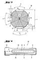
- FIG. 1-4 shows the clamping area of the shaft of a drilling and / or chiseling tool, which can be inserted into the tool holder of a hand-held power tool, for example a drilling and / or chiseling device from the applicant.
- the tool shank 2 has a diameter t in the clamping area 3 which is equal to or larger than 12 mm.
- the diameter t is preferably approximately 14 mm.
- 1-3 show a cross section of the tool; 4 shows a view of an exemplary embodiment of the tool according to the invention.
- the embodiment of the tool shown in FIG. 1 bears the reference number 1 overall.
- the illustration shows a cross section of the clamping area 3 of the shank 2 of the tool 1.
- An axially closed locking recess is designated by 4.
- the preferably circular arc-shaped locking recess 4 opens with edges 8 into the circumference of the shaft 2.
- the radii from the axis A of the shaft 2 to the mouth edges 8 of the locking recess 4 include an opening angle, which is denoted by ⁇ .
- the opening angle is equal to or greater than 50 °.
- the depth v of the locking recess 4 is approximately 2.5 mm.
- the side surface 5 of the clamping area 3 opposite the axially closed locking recess 4 is flattened so that the tool 1 can also be inserted into tool holders with two opposing locking bodies.
- the reference points for the angular distance of the rotary driving groove 6 from the groove-like locking recess 4 are the central region of the rotating driving groove 6 and the region closest to the axis of the bottom of the locking recess 4.
- the rotary driving groove 6 is essentially trapezoidal in cross section.
- the side surfaces of the rotary driving groove 6 open with edges 9 into the circumference of the shaft.
- the radii extending from the axis A to the mouth edges 9 include an opening angle ⁇ which is equal to or greater than 50 °.
- the opening angles ⁇ , ⁇ of the locking recess 4 and the rotary driving groove 6 are approximately the same size.
- the term “approximately the same size” includes an angle difference of up to approximately ⁇ 10 °, preferably ⁇ 6 °.
- the depth d of the rotary driving groove is greater than 2.5 mm and is preferably approximately 2.6 mm with a tool shank diameter t of approximately 14 mm.
- the side surface 7 of the shaft 2 opposite the rotary driving groove 6 is flattened designed so that the tool can also be used in tool holders that have two mutually opposite rotary driving bars.
- the side surface 7 preferably opens at approximately 90 ° into the side surface 5 opposite the locking recess.
- the exemplary embodiment of the drilling and / or chiseling tool according to the invention shown in FIG. 2 is designated overall by 20.
- the shaft has the reference number 22, and the clamping area shown in cross section is designated by 23.
- the shaft 22 has two locking recesses 24 which are diametrically opposite one another and are arranged on both sides of a rotary driving groove 26. Both locking recesses 24 are arranged offset by approximately 90 ° with respect to the rotary driving groove 26.
- the side 27 of the shaft 22 opposite the rotary driving groove 26 is flattened so that the tool 20 can also be inserted into a tool holder with two rotating driving bars opposite one another.
- the locking recesses 24 lying diametrically opposite one another have the same opening angle ⁇ .
- the opening angles of the locking recesses 24 and the rotary driving groove 26 are equal to or greater than 50 °. Again, they are preferably approximately the same size.
- the distance a of the region of the rotary driving groove 26 closest to the axis has a ratio to the radius t / 2 of the shaft 22, the value of which is less than 0.65.
- the distance s between the regions closest to the axis of the opposing locking recesses 24 is related to the diameter t of the shaft 22 at the clamping region 23, which is between approximately 0.6 to 0.7.
- the locking cutouts 24 preferably have an arc-shaped cross section.
- the radius r of the circular arc is in a ratio of about 0.54 to about 0.6 to the diameter of the shaft 22 at the clamping area.
- FIGS. 3 and 4 A further exemplary embodiment of the tool according to the invention is shown in FIGS. 3 and 4 and is provided with the reference number 30 as a whole.
- the clamping area 33 of the shaft 32 is equipped with two locking recesses 34 and two rotary driving grooves 36, which are diametrically opposite each other.
- the diametrically opposite rotary driving grooves 36 have the same opening angle ⁇ , which are approximately the same size as the opening angle of the Locking recesses 34.
- the mouth edge 8 of the rotary driving groove 36 which faces away from the locking recess 34 following along the circumference of the shaft 32, has an angular distance from the correspondingly assigned mouth edge 9 of the locking recess 34, which is preferably approximately 90 °.
Landscapes
- Engineering & Computer Science (AREA)
- Mechanical Engineering (AREA)
- Gripping On Spindles (AREA)
- Surgical Instruments (AREA)
- Portable Power Tools In General (AREA)
Applications Claiming Priority (2)
| Application Number | Priority Date | Filing Date | Title |
|---|---|---|---|
| DE19819631A DE19819631A1 (de) | 1998-05-04 | 1998-05-04 | Werkzeug für Handwerkzeugmaschinen |
| DE19819631 | 1998-05-04 |
Publications (2)
| Publication Number | Publication Date |
|---|---|
| EP0955131A1 true EP0955131A1 (fr) | 1999-11-10 |
| EP0955131B1 EP0955131B1 (fr) | 2005-02-09 |
Family
ID=7866478
Family Applications (1)
| Application Number | Title | Priority Date | Filing Date |
|---|---|---|---|
| EP99810215A Expired - Lifetime EP0955131B1 (fr) | 1998-05-04 | 1999-03-11 | Outil à machines-outils à main |
Country Status (6)
| Country | Link |
|---|---|
| US (1) | US6174112B1 (fr) |
| EP (1) | EP0955131B1 (fr) |
| JP (1) | JPH11333759A (fr) |
| CN (1) | CN1096337C (fr) |
| DE (2) | DE19819631A1 (fr) |
| DK (1) | DK0955131T3 (fr) |
Cited By (2)
| Publication number | Priority date | Publication date | Assignee | Title |
|---|---|---|---|---|
| DE10241054A1 (de) * | 2002-09-05 | 2004-03-18 | Robert Bosch Gmbh | Werkzeug und Werkzeughalter für eine Handwerkzeugmaschine |
| EP1602452A3 (fr) * | 2004-06-02 | 2006-01-11 | HILTI Aktiengesellschaft | Tige pour un outil rotatif et/ou à percussion |
Families Citing this family (3)
| Publication number | Priority date | Publication date | Assignee | Title |
|---|---|---|---|---|
| GB2393931A (en) * | 2002-10-10 | 2004-04-14 | Black & Decker Inc | Tool for a rotary hammer |
| DE10357380A1 (de) * | 2003-12-05 | 2005-06-30 | Hilti Ag | Einsteckende für ein drehendes und/oder schlagendes Werkzeug |
| US20120074659A1 (en) | 2010-09-29 | 2012-03-29 | Henry H. Hamilton | Tool assembly and related methods |
Citations (8)
| Publication number | Priority date | Publication date | Assignee | Title |
|---|---|---|---|---|
| DE2650134A1 (de) * | 1976-10-30 | 1978-05-11 | Bosch Gmbh Robert | Werkzeugeinsteckschaft |
| EP0181093A1 (fr) * | 1984-10-08 | 1986-05-14 | Dom Holdings Plc | Outil |
| EP0433876A1 (fr) | 1989-12-16 | 1991-06-26 | HILTI Aktiengesellschaft | Outil pour le forage à percussion et porte-outil pour outil de forage à percussion |
| DE9319009U1 (de) | 1993-12-10 | 1994-02-03 | Plica Werkzeugfabrik Ag, Mollis | Dreischneidenbohrer |
| EP0584706A2 (fr) | 1992-08-22 | 1994-03-02 | Robert Bosch Gmbh | Outil pour outils à main |
| DE4303545A1 (de) | 1993-02-08 | 1994-08-11 | Hawera Probst Kg Hartmetall | Einrichtung an Handwerkzeugmaschinen zur Drehmomentübertragung |
| DE4338818A1 (de) * | 1993-11-13 | 1995-05-18 | Hawera Probst Kg Hartmetall | Einrichtung an Handwerkzeugmaschinen zur Drehmomentübertragung |
| EP0500489B1 (fr) | 1991-02-21 | 1995-08-23 | HILTI Aktiengesellschaft | Outil et porte-outil pour machine à main |
Family Cites Families (3)
| Publication number | Priority date | Publication date | Assignee | Title |
|---|---|---|---|---|
| DE1752155A1 (de) * | 1968-04-10 | 1971-05-13 | Hilti Ag | Werkzeug fuer Werkzeughalter fuer Bohrhaemmer |
| DE4210451A1 (de) * | 1992-03-30 | 1993-10-07 | Plica Werkzeugfabrik Ag Mollis | Einrichtung zur Drehmomentübertragung |
| US5421628A (en) * | 1994-01-28 | 1995-06-06 | Nahm; Hyong K. | Water-repellent shield for automobile side mirror |
-
1998
- 1998-05-04 DE DE19819631A patent/DE19819631A1/de not_active Withdrawn
-
1999
- 1999-03-11 EP EP99810215A patent/EP0955131B1/fr not_active Expired - Lifetime
- 1999-03-11 DK DK99810215T patent/DK0955131T3/da active
- 1999-03-11 DE DE59911573T patent/DE59911573D1/de not_active Expired - Lifetime
- 1999-04-20 CN CN99105099A patent/CN1096337C/zh not_active Expired - Fee Related
- 1999-04-28 JP JP11121084A patent/JPH11333759A/ja active Pending
- 1999-05-07 US US09/306,868 patent/US6174112B1/en not_active Expired - Lifetime
Patent Citations (8)
| Publication number | Priority date | Publication date | Assignee | Title |
|---|---|---|---|---|
| DE2650134A1 (de) * | 1976-10-30 | 1978-05-11 | Bosch Gmbh Robert | Werkzeugeinsteckschaft |
| EP0181093A1 (fr) * | 1984-10-08 | 1986-05-14 | Dom Holdings Plc | Outil |
| EP0433876A1 (fr) | 1989-12-16 | 1991-06-26 | HILTI Aktiengesellschaft | Outil pour le forage à percussion et porte-outil pour outil de forage à percussion |
| EP0500489B1 (fr) | 1991-02-21 | 1995-08-23 | HILTI Aktiengesellschaft | Outil et porte-outil pour machine à main |
| EP0584706A2 (fr) | 1992-08-22 | 1994-03-02 | Robert Bosch Gmbh | Outil pour outils à main |
| DE4303545A1 (de) | 1993-02-08 | 1994-08-11 | Hawera Probst Kg Hartmetall | Einrichtung an Handwerkzeugmaschinen zur Drehmomentübertragung |
| DE4338818A1 (de) * | 1993-11-13 | 1995-05-18 | Hawera Probst Kg Hartmetall | Einrichtung an Handwerkzeugmaschinen zur Drehmomentübertragung |
| DE9319009U1 (de) | 1993-12-10 | 1994-02-03 | Plica Werkzeugfabrik Ag, Mollis | Dreischneidenbohrer |
Cited By (2)
| Publication number | Priority date | Publication date | Assignee | Title |
|---|---|---|---|---|
| DE10241054A1 (de) * | 2002-09-05 | 2004-03-18 | Robert Bosch Gmbh | Werkzeug und Werkzeughalter für eine Handwerkzeugmaschine |
| EP1602452A3 (fr) * | 2004-06-02 | 2006-01-11 | HILTI Aktiengesellschaft | Tige pour un outil rotatif et/ou à percussion |
Also Published As
| Publication number | Publication date |
|---|---|
| EP0955131B1 (fr) | 2005-02-09 |
| DE19819631A1 (de) | 1999-11-11 |
| US6174112B1 (en) | 2001-01-16 |
| CN1096337C (zh) | 2002-12-18 |
| DE59911573D1 (de) | 2005-03-17 |
| DK0955131T3 (da) | 2005-06-13 |
| JPH11333759A (ja) | 1999-12-07 |
| CN1234320A (zh) | 1999-11-10 |
Similar Documents
| Publication | Publication Date | Title |
|---|---|---|
| DE3037097C2 (de) | Vollbohrwerkzeug, insbesondere Spiralbohrer | |
| EP0432169B1 (fr) | Dispositif de transmission de couple sur les machines-outils | |
| EP0433876B1 (fr) | Outil pour le forage à percussion et porte-outil pour outil de forage à percussion | |
| DE102006016804A1 (de) | Werkzeughalterung für einen Bohrhammer | |
| EP0813926A1 (fr) | Fraise pour le copiage | |
| DE3413581A1 (de) | Schlagbohreinrichtung | |
| EP0551795B1 (fr) | Outil pour forage à percussion et ciselage et mandrin pour cet outil | |
| EP0553124A1 (fr) | Dispositif pour machines-outils manuelles. | |
| EP0739267A1 (fr) | Dispositif d'entrainement en rotation d'outils pour machines-outils manuelles | |
| EP0614731B1 (fr) | Outil et mandrin pour outil à main | |
| EP3741483A1 (fr) | Plaquette de coupe, porte-plaquette et dispositif de coupe | |
| DE3416986A1 (de) | Bohrfutter zum schlagbohren | |
| EP1211005A1 (fr) | Mandrin | |
| EP1234628A2 (fr) | Mors de serrage | |
| EP0955131B1 (fr) | Outil à machines-outils à main | |
| DE7806211U1 (de) | Bohrwerkzeug fuer bohrungen in metallvollmaterial von werkstuecken | |
| EP0804986B1 (fr) | Elément de coupe | |
| DE3413005C2 (de) | Werkzeugschaft mit mehreren axial verlaufenden Nuten | |
| DE4402802C2 (de) | Werkzeug und Werkzeugaufnahme für Handwerkzeuggeräte | |
| DE3315661A1 (de) | Spannfutter fuer ein werkzeug zum schlagbohren | |
| DE10206164B4 (de) | Einspannschaft | |
| DE8519793U1 (de) | Werkzeugwechselvorrichtung für eine Werkzeugmaschine | |
| CH695549A5 (de) | Elektrowerkzeugmaschine mit einer an einen Werkzeughalter koppelbaren Antriebsspindel. | |
| EP0581726B1 (fr) | Outil et mandrin pour outil portatif | |
| DE2056382A1 (de) | Verbindung mit Schrumpf- oder Preßsitz |
Legal Events
| Date | Code | Title | Description |
|---|---|---|---|
| PUAI | Public reference made under article 153(3) epc to a published international application that has entered the european phase |
Free format text: ORIGINAL CODE: 0009012 |
|
| AK | Designated contracting states |
Kind code of ref document: A1 Designated state(s): CH DE DK FR GB LI SE |
|
| AX | Request for extension of the european patent |
Free format text: AL;LT;LV;MK;RO;SI |
|
| 17P | Request for examination filed |
Effective date: 20000510 |
|
| AKX | Designation fees paid |
Free format text: CH DE DK FR GB LI SE |
|
| 17Q | First examination report despatched |
Effective date: 20030915 |
|
| GRAP | Despatch of communication of intention to grant a patent |
Free format text: ORIGINAL CODE: EPIDOSNIGR1 |
|
| GRAS | Grant fee paid |
Free format text: ORIGINAL CODE: EPIDOSNIGR3 |
|
| GRAA | (expected) grant |
Free format text: ORIGINAL CODE: 0009210 |
|
| AK | Designated contracting states |
Kind code of ref document: B1 Designated state(s): CH DE DK FR GB LI SE |
|
| REG | Reference to a national code |
Ref country code: GB Ref legal event code: FG4D Free format text: NOT ENGLISH |
|
| REG | Reference to a national code |
Ref country code: CH Ref legal event code: EP |
|
| REG | Reference to a national code |
Ref country code: SE Ref legal event code: TRGR |
|
| REF | Corresponds to: |
Ref document number: 59911573 Country of ref document: DE Date of ref document: 20050317 Kind code of ref document: P |
|
| GBT | Gb: translation of ep patent filed (gb section 77(6)(a)/1977) |
Effective date: 20050407 |
|
| REG | Reference to a national code |
Ref country code: DK Ref legal event code: T3 |
|
| PLBE | No opposition filed within time limit |
Free format text: ORIGINAL CODE: 0009261 |
|
| STAA | Information on the status of an ep patent application or granted ep patent |
Free format text: STATUS: NO OPPOSITION FILED WITHIN TIME LIMIT |
|
| ET | Fr: translation filed | ||
| 26N | No opposition filed |
Effective date: 20051110 |
|
| PGFP | Annual fee paid to national office [announced via postgrant information from national office to epo] |
Ref country code: DK Payment date: 20090313 Year of fee payment: 11 |
|
| PGFP | Annual fee paid to national office [announced via postgrant information from national office to epo] |
Ref country code: CH Payment date: 20090317 Year of fee payment: 11 |
|
| PGFP | Annual fee paid to national office [announced via postgrant information from national office to epo] |
Ref country code: SE Payment date: 20090306 Year of fee payment: 11 |
|
| REG | Reference to a national code |
Ref country code: CH Ref legal event code: PL |
|
| EUG | Se: european patent has lapsed | ||
| REG | Reference to a national code |
Ref country code: DK Ref legal event code: EBP |
|
| PG25 | Lapsed in a contracting state [announced via postgrant information from national office to epo] |
Ref country code: LI Free format text: LAPSE BECAUSE OF NON-PAYMENT OF DUE FEES Effective date: 20100331 Ref country code: CH Free format text: LAPSE BECAUSE OF NON-PAYMENT OF DUE FEES Effective date: 20100331 |
|
| PG25 | Lapsed in a contracting state [announced via postgrant information from national office to epo] |
Ref country code: DK Free format text: LAPSE BECAUSE OF NON-PAYMENT OF DUE FEES Effective date: 20100331 |
|
| PGFP | Annual fee paid to national office [announced via postgrant information from national office to epo] |
Ref country code: FR Payment date: 20120319 Year of fee payment: 14 |
|
| PGFP | Annual fee paid to national office [announced via postgrant information from national office to epo] |
Ref country code: DE Payment date: 20120215 Year of fee payment: 14 |
|
| PGFP | Annual fee paid to national office [announced via postgrant information from national office to epo] |
Ref country code: GB Payment date: 20120307 Year of fee payment: 14 |
|
| PG25 | Lapsed in a contracting state [announced via postgrant information from national office to epo] |
Ref country code: SE Free format text: LAPSE BECAUSE OF NON-PAYMENT OF DUE FEES Effective date: 20100312 |
|
| GBPC | Gb: european patent ceased through non-payment of renewal fee |
Effective date: 20130311 |
|
| REG | Reference to a national code |
Ref country code: FR Ref legal event code: ST Effective date: 20131129 |
|
| REG | Reference to a national code |
Ref country code: DE Ref legal event code: R119 Ref document number: 59911573 Country of ref document: DE Effective date: 20131001 |
|
| PG25 | Lapsed in a contracting state [announced via postgrant information from national office to epo] |
Ref country code: GB Free format text: LAPSE BECAUSE OF NON-PAYMENT OF DUE FEES Effective date: 20130311 Ref country code: DE Free format text: LAPSE BECAUSE OF NON-PAYMENT OF DUE FEES Effective date: 20131001 Ref country code: FR Free format text: LAPSE BECAUSE OF NON-PAYMENT OF DUE FEES Effective date: 20130402 |