EP0181093A1 - Outil - Google Patents
Outil Download PDFInfo
- Publication number
- EP0181093A1 EP0181093A1 EP85307150A EP85307150A EP0181093A1 EP 0181093 A1 EP0181093 A1 EP 0181093A1 EP 85307150 A EP85307150 A EP 85307150A EP 85307150 A EP85307150 A EP 85307150A EP 0181093 A1 EP0181093 A1 EP 0181093A1
- Authority
- EP
- European Patent Office
- Prior art keywords
- tool
- shank
- tool according
- intersection
- receiver
- Prior art date
- Legal status (The legal status is an assumption and is not a legal conclusion. Google has not performed a legal analysis and makes no representation as to the accuracy of the status listed.)
- Granted
Links
Images
Classifications
-
- B—PERFORMING OPERATIONS; TRANSPORTING
- B25—HAND TOOLS; PORTABLE POWER-DRIVEN TOOLS; MANIPULATORS
- B25D—PERCUSSIVE TOOLS
- B25D17/00—Details of, or accessories for, portable power-driven percussive tools
- B25D17/08—Means for retaining and guiding the tool bit, e.g. chucks allowing axial oscillation of the tool bit
- B25D17/084—Rotating chucks or sockets
- B25D17/088—Rotating chucks or sockets with radial movable locking elements co-operating with bit shafts specially adapted therefor
-
- B—PERFORMING OPERATIONS; TRANSPORTING
- B25—HAND TOOLS; PORTABLE POWER-DRIVEN TOOLS; MANIPULATORS
- B25D—PERCUSSIVE TOOLS
- B25D2217/00—Details of, or accessories for, portable power-driven percussive tools
- B25D2217/003—Details relating to chucks with radially movable locking elements
- B25D2217/0034—Details of shank profiles
-
- Y—GENERAL TAGGING OF NEW TECHNOLOGICAL DEVELOPMENTS; GENERAL TAGGING OF CROSS-SECTIONAL TECHNOLOGIES SPANNING OVER SEVERAL SECTIONS OF THE IPC; TECHNICAL SUBJECTS COVERED BY FORMER USPC CROSS-REFERENCE ART COLLECTIONS [XRACs] AND DIGESTS
- Y10—TECHNICAL SUBJECTS COVERED BY FORMER USPC
- Y10S—TECHNICAL SUBJECTS COVERED BY FORMER USPC CROSS-REFERENCE ART COLLECTIONS [XRACs] AND DIGESTS
- Y10S279/00—Chucks or sockets
- Y10S279/904—Quick change socket
- Y10S279/905—Quick change socket with ball detent
-
- Y—GENERAL TAGGING OF NEW TECHNOLOGICAL DEVELOPMENTS; GENERAL TAGGING OF CROSS-SECTIONAL TECHNOLOGIES SPANNING OVER SEVERAL SECTIONS OF THE IPC; TECHNICAL SUBJECTS COVERED BY FORMER USPC CROSS-REFERENCE ART COLLECTIONS [XRACs] AND DIGESTS
- Y10—TECHNICAL SUBJECTS COVERED BY FORMER USPC
- Y10T—TECHNICAL SUBJECTS COVERED BY FORMER US CLASSIFICATION
- Y10T279/00—Chucks or sockets
- Y10T279/17—Socket type
- Y10T279/17666—Radially reciprocating jaws
- Y10T279/17692—Moving-cam actuator
- Y10T279/17743—Reciprocating cam sleeve
- Y10T279/17752—Ball or roller jaws
-
- Y—GENERAL TAGGING OF NEW TECHNOLOGICAL DEVELOPMENTS; GENERAL TAGGING OF CROSS-SECTIONAL TECHNOLOGIES SPANNING OVER SEVERAL SECTIONS OF THE IPC; TECHNICAL SUBJECTS COVERED BY FORMER USPC CROSS-REFERENCE ART COLLECTIONS [XRACs] AND DIGESTS
- Y10—TECHNICAL SUBJECTS COVERED BY FORMER USPC
- Y10T—TECHNICAL SUBJECTS COVERED BY FORMER US CLASSIFICATION
- Y10T408/00—Cutting by use of rotating axially moving tool
- Y10T408/89—Tool or Tool with support
- Y10T408/907—Tool or Tool with support including detailed shank
Definitions
- the invention relates to a tool, particularly a tool for insertion in the tool receiver of a rotary percussive or rotary machine, such as a drilling machine.
- a tool for insertion in the tool receiver of a rotary percussive or rotary machine comprising a shank, a first surface extending from a point of intersection with a boundary surface of the shank to a position along the length of the shank, and a second surface extending from or from near one longitudinal edge of the first surface at an obtuse angle and intersecting a further boundary surface of the shank, the arrangement being such that the second surface is adapted to be drivingly engaged by a elongate driving means of the tool receiver in use.
- a tool for insertion in the tool receiver of a rotary percussive or rotary machine comprising a shank, a first surface extending transversely of the shank from a point of intersection with the periphery thereof, and a second surface extending away from the first surface at the end thereof remote from the point of intersection of the first surface with the periphery of the shank to a point of intersection with the periphery spaced from the first-mentioned point of intersection the arrangement being such that the second mentioned surface is adapted to be drivingly engaged by an elongate driving means of the tool receiver in use.
- first and second surfaces spaced apart on opposite sides of the longitudinal axis of the shank.
- Each first surface may be substantially flat.
- Each second surface may be substantially flat.
- the angle between respective first and second surfaces may be in the range 100° to 110 * 45'.
- a plane through the centre of the shank at substantially 90° to each first flat surface may be intermediate the point of intersection of each first surface with the periphery of the shank and the end from which the respective second surface extends.
- the shank may be cylindrical and each second surface may be a radial surface.
- the two sets of first and second surfaces may be spaced apart on opposite sides of the longitudinal axis of the shank.
- the second flat surfaces may lie on a diameter of the shank.
- the angle may be 110° 30'.
- the second and third surface may terminate in a curved part at the boundary surface of the shank.
- the radius of the curved part may be about 0.5 mm.
- the width of the first surface may be about 3.00 mm.
- the first surface may terminate at said position remote from the boundary surface in a configuration which is concave.
- the first surface may terminate in a quadrant shaped surface at an end thereof remote from an end of the shank.
- the seating means may comprise a blind elongate surface groove between the first and second surface.
- the further groove may be arcuate.
- the radius of the arc may be about 6.80 mm.
- the end of the shank inserted in use in the tool holder may be chamfered.
- apparatus comprising a tool as hereinbefore defined, and a rotary percussive or rotary machine the tool being received by the tool receiver thereof with an elongate driving means of the tool receiver in driving engagement with the or each second surface, for transferring rotary drive from the machine to the tool.
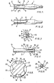
- the tool 1 shown is a drill which has a cylindrical shank 2 for insertion in a tool holder of a rotary percussive or rotary machine such as a drilling machine.
- the shank 2 has a first surface 3 extending transversely of the shank 2 from a point of intersection 4 with the periphery thereof and a second surface 5 extending from the first surface 3 at the end thereof remote from the point of intersection 4 of the first surface 3 with the periphery of the shank 2 to a point of intersection 7 with the periphery spaced from the point of intersection 4 of the first surface 3 with the periphery.
- the first and second surfaces 3 and 5 are flat.
- the second surfaces 5 are radial and arranged on the same diameter.
- a plane through the longitudinal axis 8 of the shank 2 at substantially 90° to the first flat surfaces 3 (which are parallel) is intermediate their respective points of intersection 4 with the periphery and the ends from which the respective second flat surfaces 5 extend.
- Each first flat surface 3 thus provides a large, flat bearing for cooperation with an elongate driving member (a spline or rib) (not shown) of the tool holder (also not shown).
- the angle between a first flat surface 3 and a respective second flat 5 surface is 110° 30' + 15', for optimum driving engagement with the spline or rib which is of wedge shape.
- the shank 2 also has opposite blind elongate surface grooves 9, between the sets of first and second surfaces 3 and 4 which receive spherical or cylindrical locking members 10 (shown dashed) of the tool holder when the tool 1 is inserted in the tool holder.
- spherical or cylindrical locking members 10 shown dashed
- the ribs or splines slide along the first flat surfaces 3 and engage the second flat surfaces 5 so that on rotation of the tool holder torque is transmitted to the shank 2, and then to the tool 1, through the second flat surfaces 5.
- first flat surfaces 3 which terminates in a rounded or quadrant shaped end 11 inboard of the shank ensures that there is always positive alignment and easy insertion even when the ribs or splines of the holder, or the second flat surfaces 5 become worn, bent or deformed.
- the tool 12 shown is a drill which has a cylindrical shank 13 for insertion in a tool holder of a rotary percussive or rotary machine such as a drilling machine.
- the shank 13 has two opposite sets of first, second and third surfaces 14,15,16, which are diametrically opposed.
- the first surfaces 14 are each flat, and each second and third surfaces 15 and 16 extends from a respective end thereof to the curved boundary surface 17 of the (cylindrical) shank 13.
- the second and third surfaces 15 and 16 converge towards one another in the direction towards the interior of the shank 13.
- each second and third surfaces 15 and 16 terminate in a convex part 18 of radius 0.5 mm.
- first, second and third surfaces 14,15,16 each define a groove 19 which extends from a boundary surface defining one end 20 of the shank 13 longitudinally thereof away from that one end and terminating in a shallow curve 21 which intersects with the cylindrical boundary surface 17 of the shank 13.
- the shank 13 has a chamfered part 22 extending between the surface 17 to the surface 20.
- This means comprises a pair of diametrically opposed elongate blind slots 23 (situated on a diameter at 90° to that on which the opposite grooves 19 are located). Each slot 23 has opposite radiused ends 24, and receives in use a ball 25, as shown in dashed lines in Fig. 6.
- the locking means also includes a peripheral groove 27 adjacent the end 20.
- the groove 27 is arcuate, of radius 6.80 mm and it intersects grooves 19 adjacent the end 20.
- the chamfered end 20 of the tool is inserted in the tool receiver so that the balls 26 engage in the slots 23 and a further ball or balls engage in the groove 27.
- the balls are spring mounted so that they can move out of the way of the tool as it is inserted, and spring into position in respective grooves when the tool is in position.
- the balls likewise move out of position to allow the tool to be removed from the tool receiver, the curved ends 24 and the curve of the groove 27 gradually easing the balls out of engagement to release the tool.
- the chanfered surface 22 aids in insertion and in urgirgthe ball(s) to engage in groove 27 radially outwards prior to snapping over part 28 into the groove 27.
- Driving ribs or splines (not shown) of the tool receiver engage in the grooves 19, the curved parts 18 of the second and third surfaces 15 and 16, facilitating entry thereof.
- the ribs or splines then engage at least one of the second or third surfaces for driving the tool 12 about its longitudinal axis.
- Driving torque is thus transmitted to the tool through the ribs or splines and the tool is positive driven, either clockwise or anti-clockwise.
Landscapes
- Mechanical Engineering (AREA)
- Engineering & Computer Science (AREA)
- Percussive Tools And Related Accessories (AREA)
- Dry Shavers And Clippers (AREA)
- Crushing And Pulverization Processes (AREA)
- Toys (AREA)
- Grinding-Machine Dressing And Accessory Apparatuses (AREA)
- Absorbent Articles And Supports Therefor (AREA)
- Prostheses (AREA)
- Materials For Medical Uses (AREA)
- Jigs For Machine Tools (AREA)
- Gripping On Spindles (AREA)
- Perforating, Stamping-Out Or Severing By Means Other Than Cutting (AREA)
- Polishing Bodies And Polishing Tools (AREA)
- Cutting Tools, Boring Holders, And Turrets (AREA)
- Input Circuits Of Receivers And Coupling Of Receivers And Audio Equipment (AREA)
Priority Applications (1)
| Application Number | Priority Date | Filing Date | Title |
|---|---|---|---|
| AT85307150T ATE52213T1 (de) | 1984-10-08 | 1985-10-07 | Werkzeug. |
Applications Claiming Priority (2)
| Application Number | Priority Date | Filing Date | Title |
|---|---|---|---|
| GB8425400 | 1984-10-08 | ||
| GB848425400A GB8425400D0 (en) | 1984-10-08 | 1984-10-08 | Tool |
Publications (2)
| Publication Number | Publication Date |
|---|---|
| EP0181093A1 true EP0181093A1 (fr) | 1986-05-14 |
| EP0181093B1 EP0181093B1 (fr) | 1990-04-25 |
Family
ID=10567866
Family Applications (1)
| Application Number | Title | Priority Date | Filing Date |
|---|---|---|---|
| EP85307150A Expired - Lifetime EP0181093B1 (fr) | 1984-10-08 | 1985-10-07 | Outil |
Country Status (13)
| Country | Link |
|---|---|
| US (1) | US4717292A (fr) |
| EP (1) | EP0181093B1 (fr) |
| AT (1) | ATE52213T1 (fr) |
| CA (1) | CA1236082A (fr) |
| DE (1) | DE3577289D1 (fr) |
| DK (1) | DK456285A (fr) |
| FI (1) | FI853887L (fr) |
| GB (2) | GB8425400D0 (fr) |
| GR (1) | GR852424B (fr) |
| IE (1) | IE57108B1 (fr) |
| NO (1) | NO167265C (fr) |
| PT (1) | PT81263B (fr) |
| ZA (1) | ZA857703B (fr) |
Cited By (9)
| Publication number | Priority date | Publication date | Assignee | Title |
|---|---|---|---|---|
| FR2635039A1 (fr) * | 1988-08-05 | 1990-02-09 | Prospection & Inventions | Foret comprenant une queue avec des rainures |
| EP0565482A1 (fr) * | 1992-04-06 | 1993-10-13 | HILTI Aktiengesellschaft | Outil et port outil pour des outils à main |
| EP0622157A1 (fr) * | 1993-04-26 | 1994-11-02 | HILTI Aktiengesellschaft | Arbre de fixation d'un outil |
| WO1995019243A1 (fr) * | 1994-01-14 | 1995-07-20 | Robert Bosch Gmbh | Dispositif d'entrainement en rotation d'outils pour machines-outils manuelles |
| EP0729810A1 (fr) * | 1995-03-03 | 1996-09-04 | DreBo Werkzeugfabrik GmbH | Foret |
| EP0955131A1 (fr) * | 1998-05-04 | 1999-11-10 | HILTI Aktiengesellschaft | Outil à machines-outils à main |
| EP2719490A1 (fr) * | 2012-10-11 | 2014-04-16 | Seco Tools Ab | Tête de coupe et outil de coupe ayant une tête de coupe remplaçable |
| WO2014056888A1 (fr) | 2012-10-11 | 2014-04-17 | Seco Tools Ab | Tête de coupe et outil de coupe ayant une tête de coupe remplaçable |
| WO2019177472A3 (fr) * | 2018-01-03 | 2019-10-24 | P.P.H.U RAF s.c. | Mandrin de forage, en particulier pour système de forage du type sds |
Families Citing this family (5)
| Publication number | Priority date | Publication date | Assignee | Title |
|---|---|---|---|---|
| DE4105414A1 (de) * | 1991-02-21 | 1992-08-27 | Hilti Ag | Werkzeug und werkzeughalter fuer handwerkzeuggeraete |
| DE4137120A1 (de) * | 1991-11-12 | 1993-05-13 | Hilti Ag | Werkzeug zum schlagbohren und werkzeugaufnahme fuer schlagbohrende werkzeuge |
| CN103447599A (zh) | 2012-06-01 | 2013-12-18 | 株式会社日研工作所 | 端铣刀的柄部构造及工具夹持具 |
| JP1526222S (fr) | 2014-08-01 | 2015-06-15 | ||
| JP1526223S (fr) | 2014-08-01 | 2015-06-15 |
Citations (4)
| Publication number | Priority date | Publication date | Assignee | Title |
|---|---|---|---|---|
| FR2218169A1 (fr) * | 1973-02-21 | 1974-09-13 | Reinholdt As H | |
| FR2282323A1 (fr) * | 1974-08-19 | 1976-03-19 | Reinholdt As | Montage d'un fleuret de marteau-perforateur |
| FR2331410A1 (fr) * | 1975-11-14 | 1977-06-10 | Bosch Gmbh Robert | Dispositif pour la transmission de couples de rotation |
| GB2096045A (en) * | 1981-04-03 | 1982-10-13 | Bosch Gmbh Robert | A tool holder |
Family Cites Families (14)
| Publication number | Priority date | Publication date | Assignee | Title |
|---|---|---|---|---|
| GB341412A (en) * | 1929-04-04 | 1931-01-12 | Mecano Ges Mit Beschraenkter H | Improvements in or relating to disc clutches |
| DE878588C (de) * | 1949-11-11 | 1953-06-05 | Stanislaus Benesch | Spanndorn zur Mitnahme eines Werkstueckes oder Werkzeuges mit einem Klemmrollengesperre |
| US2652738A (en) * | 1950-10-26 | 1953-09-22 | Gen Precision Lab Inc | Locking arbor |
| GB804110A (en) * | 1953-11-03 | 1958-11-05 | Horace Kimberley Freeman | Improvements in drilling bits |
| DE1752155A1 (de) * | 1968-04-10 | 1971-05-13 | Hilti Ag | Werkzeug fuer Werkzeughalter fuer Bohrhaemmer |
| DE1928954A1 (de) * | 1969-06-07 | 1970-12-10 | Bosch Gmbh Robert | Bohrfutter |
| AT332099B (de) * | 1973-06-20 | 1976-09-10 | Stumpp & Kurz | Bohrvorrichtung |
| SE388558B (sv) * | 1974-03-04 | 1976-10-11 | Bulten Kanthal Ab | Skruvmejsel for maskinella skruvdragare |
| US4036560A (en) * | 1975-11-03 | 1977-07-19 | Stanadyne, Inc. | Heavy duty hole saw and arbor assembly |
| DE2650134A1 (de) * | 1976-10-30 | 1978-05-11 | Bosch Gmbh Robert | Werkzeugeinsteckschaft |
| DE2746029C2 (de) * | 1977-10-13 | 1985-10-10 | Fischer, Artur, Dr.H.C., 7244 Waldachtal | Bohreinheit |
| DE2811328C2 (de) * | 1978-03-16 | 1986-09-25 | Robert Bosch Gmbh, 7000 Stuttgart | Bohrfutter |
| US4209182A (en) * | 1978-10-05 | 1980-06-24 | Cooper Industries, Inc. | Bit retainer for screwdriver |
| CH656816A5 (de) * | 1981-11-11 | 1986-07-31 | Hilti Ag | Bohrer fuer handgeraete. |
-
1984
- 1984-10-08 GB GB848425400A patent/GB8425400D0/en active Pending
-
1985
- 1985-10-07 EP EP85307150A patent/EP0181093B1/fr not_active Expired - Lifetime
- 1985-10-07 GB GB08524685A patent/GB2165173B/en not_active Expired
- 1985-10-07 FI FI853887A patent/FI853887L/fi not_active Application Discontinuation
- 1985-10-07 GR GR852424A patent/GR852424B/el unknown
- 1985-10-07 ZA ZA857703A patent/ZA857703B/xx unknown
- 1985-10-07 PT PT81263A patent/PT81263B/pt not_active IP Right Cessation
- 1985-10-07 DE DE8585307150T patent/DE3577289D1/de not_active Revoked
- 1985-10-07 NO NO853957A patent/NO167265C/no unknown
- 1985-10-07 DK DK456285A patent/DK456285A/da unknown
- 1985-10-07 IE IE2453/85A patent/IE57108B1/en unknown
- 1985-10-07 CA CA000492414A patent/CA1236082A/fr not_active Expired
- 1985-10-07 AT AT85307150T patent/ATE52213T1/de not_active IP Right Cessation
-
1987
- 1987-05-06 US US07/045,713 patent/US4717292A/en not_active Expired - Fee Related
Patent Citations (4)
| Publication number | Priority date | Publication date | Assignee | Title |
|---|---|---|---|---|
| FR2218169A1 (fr) * | 1973-02-21 | 1974-09-13 | Reinholdt As H | |
| FR2282323A1 (fr) * | 1974-08-19 | 1976-03-19 | Reinholdt As | Montage d'un fleuret de marteau-perforateur |
| FR2331410A1 (fr) * | 1975-11-14 | 1977-06-10 | Bosch Gmbh Robert | Dispositif pour la transmission de couples de rotation |
| GB2096045A (en) * | 1981-04-03 | 1982-10-13 | Bosch Gmbh Robert | A tool holder |
Cited By (14)
| Publication number | Priority date | Publication date | Assignee | Title |
|---|---|---|---|---|
| EP0355071A1 (fr) * | 1988-08-05 | 1990-02-21 | Societe De Prospection Et D'inventions Techniques Spit | Foret comprenant une queue avec des rainures |
| FR2635039A1 (fr) * | 1988-08-05 | 1990-02-09 | Prospection & Inventions | Foret comprenant une queue avec des rainures |
| EP0565482A1 (fr) * | 1992-04-06 | 1993-10-13 | HILTI Aktiengesellschaft | Outil et port outil pour des outils à main |
| KR100287512B1 (ko) * | 1993-04-26 | 2001-04-16 | 빌리 로날드, 슈날쯔지 안드레아 | 수공구장치용공구홀더와이공구홀더에장착되는공구 |
| EP0622157A1 (fr) * | 1993-04-26 | 1994-11-02 | HILTI Aktiengesellschaft | Arbre de fixation d'un outil |
| WO1995019243A1 (fr) * | 1994-01-14 | 1995-07-20 | Robert Bosch Gmbh | Dispositif d'entrainement en rotation d'outils pour machines-outils manuelles |
| EP0729810A1 (fr) * | 1995-03-03 | 1996-09-04 | DreBo Werkzeugfabrik GmbH | Foret |
| EP0955131A1 (fr) * | 1998-05-04 | 1999-11-10 | HILTI Aktiengesellschaft | Outil à machines-outils à main |
| US6174112B1 (en) | 1998-05-04 | 2001-01-16 | Hilti Aktiengesellschaft | Tool for hand-held equipment |
| CN1096337C (zh) * | 1998-05-04 | 2002-12-18 | 希尔蒂股份公司 | 手工工具机的工具 |
| EP2719490A1 (fr) * | 2012-10-11 | 2014-04-16 | Seco Tools Ab | Tête de coupe et outil de coupe ayant une tête de coupe remplaçable |
| WO2014056888A1 (fr) | 2012-10-11 | 2014-04-17 | Seco Tools Ab | Tête de coupe et outil de coupe ayant une tête de coupe remplaçable |
| US9999929B2 (en) | 2012-10-11 | 2018-06-19 | Seco Tools Ab | Cutting head and cutting tool having a replaceable cutting head |
| WO2019177472A3 (fr) * | 2018-01-03 | 2019-10-24 | P.P.H.U RAF s.c. | Mandrin de forage, en particulier pour système de forage du type sds |
Also Published As
| Publication number | Publication date |
|---|---|
| DK456285A (da) | 1986-04-09 |
| PT81263A (en) | 1985-11-01 |
| IE852453L (en) | 1986-04-08 |
| FI853887A7 (fi) | 1986-04-09 |
| GB8524685D0 (en) | 1985-11-13 |
| GB2165173B (en) | 1988-08-17 |
| FI853887L (fi) | 1986-04-09 |
| GB2165173A (en) | 1986-04-09 |
| DE3577289D1 (de) | 1990-05-31 |
| GR852424B (fr) | 1986-02-04 |
| CA1236082A (fr) | 1988-05-03 |
| NO853957L (no) | 1986-04-09 |
| FI853887A0 (fi) | 1985-10-07 |
| US4717292A (en) | 1988-01-05 |
| IE57108B1 (en) | 1992-04-22 |
| PT81263B (pt) | 1987-09-18 |
| ZA857703B (en) | 1987-11-25 |
| NO167265B (no) | 1991-07-15 |
| DK456285D0 (da) | 1985-10-07 |
| ATE52213T1 (de) | 1990-05-15 |
| NO167265C (no) | 1991-10-23 |
| EP0181093B1 (fr) | 1990-04-25 |
| GB8425400D0 (en) | 1984-11-14 |
Similar Documents
| Publication | Publication Date | Title |
|---|---|---|
| EP0181093A1 (fr) | Outil | |
| JP4404629B2 (ja) | 切削工具 | |
| US6623202B2 (en) | Toothed tool coupling for rotating a rotary tool | |
| AU746527B2 (en) | Cutting head and tool holder coupling | |
| US5019080A (en) | Drive system for prosthetic fasteners | |
| US5435680A (en) | Screw drive construction | |
| EP1239984B1 (fr) | Ensemble porte-outil et tete amovible a montage ajuste par contraction | |
| EP0458449A1 (fr) | Entraîneur avec moyens de rétension pour les fixateurs | |
| EP1048197A1 (fr) | Ensemble lames pour faucheuse rotative | |
| CN103458805A (zh) | 切割刀柄部构型 | |
| US10556275B2 (en) | Mine drill system with adapter | |
| EP3427875A1 (fr) | Outil de forage rotatif comportant des surfaces de centrage d'insert | |
| JPH10507246A (ja) | ドリル,特にドリルねじ | |
| AU756077B2 (en) | Mounting of a rotatable chisel in mining machinery | |
| WO1989000484A1 (fr) | Burin | |
| JPH11285911A (ja) | ドリル工具及び/又はたがね工具 | |
| US9241448B2 (en) | Cutting tool for use with a stump cutting apparatus | |
| GB2158366A (en) | Means for securing cutting or breaker elements to a rotatable member | |
| EP0188083A1 (fr) | Outil | |
| EP0430572A2 (fr) | Accouplement | |
| WO1992005918A1 (fr) | Systeme de fixation | |
| EP0248775A1 (fr) | Foret | |
| JP2020527467A (ja) | 回転式切削インサート、および下り勾配付き軸方向支持表面を有する工具 | |
| JP7364551B2 (ja) | 回転式切削インサート、および軸方向係止部材を有する工具 | |
| AU742424B2 (en) | Drill bits and holders therefor |
Legal Events
| Date | Code | Title | Description |
|---|---|---|---|
| PUAI | Public reference made under article 153(3) epc to a published international application that has entered the european phase |
Free format text: ORIGINAL CODE: 0009012 |
|
| AK | Designated contracting states |
Kind code of ref document: A1 Designated state(s): AT BE CH DE FR GB IT LI LU NL SE |
|
| 17P | Request for examination filed |
Effective date: 19861107 |
|
| 17Q | First examination report despatched |
Effective date: 19880422 |
|
| GRAA | (expected) grant |
Free format text: ORIGINAL CODE: 0009210 |
|
| AK | Designated contracting states |
Kind code of ref document: B1 Designated state(s): AT BE CH DE FR GB IT LI LU NL SE |
|
| REF | Corresponds to: |
Ref document number: 52213 Country of ref document: AT Date of ref document: 19900515 Kind code of ref document: T |
|
| REF | Corresponds to: |
Ref document number: 3577289 Country of ref document: DE Date of ref document: 19900531 |
|
| ITF | It: translation for a ep patent filed | ||
| ET | Fr: translation filed | ||
| PLBI | Opposition filed |
Free format text: ORIGINAL CODE: 0009260 |
|
| ITTA | It: last paid annual fee | ||
| PG25 | Lapsed in a contracting state [announced via postgrant information from national office to epo] |
Ref country code: LU Free format text: LAPSE BECAUSE OF NON-PAYMENT OF DUE FEES Effective date: 19901031 |
|
| PGFP | Annual fee paid to national office [announced via postgrant information from national office to epo] |
Ref country code: NL Payment date: 19901031 Year of fee payment: 6 |
|
| PGFP | Annual fee paid to national office [announced via postgrant information from national office to epo] |
Ref country code: GB Payment date: 19901113 Year of fee payment: 6 |
|
| 26 | Opposition filed |
Opponent name: ROBERT BOSCH GMBH Effective date: 19900918 |
|
| PGFP | Annual fee paid to national office [announced via postgrant information from national office to epo] |
Ref country code: FR Payment date: 19901127 Year of fee payment: 6 |
|
| PGFP | Annual fee paid to national office [announced via postgrant information from national office to epo] |
Ref country code: BE Payment date: 19901128 Year of fee payment: 6 Ref country code: AT Payment date: 19901128 Year of fee payment: 6 |
|
| PGFP | Annual fee paid to national office [announced via postgrant information from national office to epo] |
Ref country code: SE Payment date: 19901129 Year of fee payment: 6 |
|
| PGFP | Annual fee paid to national office [announced via postgrant information from national office to epo] |
Ref country code: LU Payment date: 19901130 Year of fee payment: 6 |
|
| PGFP | Annual fee paid to national office [announced via postgrant information from national office to epo] |
Ref country code: CH Payment date: 19901203 Year of fee payment: 6 |
|
| PGFP | Annual fee paid to national office [announced via postgrant information from national office to epo] |
Ref country code: DE Payment date: 19901228 Year of fee payment: 6 |
|
| NLR1 | Nl: opposition has been filed with the epo |
Opponent name: ROBERT BOSCH GMBH. |
|
| EPTA | Lu: last paid annual fee | ||
| RDAG | Patent revoked |
Free format text: ORIGINAL CODE: 0009271 |
|
| STAA | Information on the status of an ep patent application or granted ep patent |
Free format text: STATUS: PATENT REVOKED |
|
| REG | Reference to a national code |
Ref country code: CH Ref legal event code: PL |
|
| 27W | Patent revoked |
Effective date: 19910801 |
|
| GBPR | Gb: patent revoked under art. 102 of the ep convention designating the uk as contracting state | ||
| NLR2 | Nl: decision of opposition | ||
| BERE | Be: lapsed |
Owner name: DOM HOLDINGS P.L.C. Effective date: 19911031 |
|
| EUG | Se: european patent has lapsed |
Ref document number: 85307150.4 Effective date: 19911218 |