EP0955135B1 - Machine à débiter en tranches un produit en forme de pain - Google Patents
Machine à débiter en tranches un produit en forme de pain Download PDFInfo
- Publication number
- EP0955135B1 EP0955135B1 EP99108048A EP99108048A EP0955135B1 EP 0955135 B1 EP0955135 B1 EP 0955135B1 EP 99108048 A EP99108048 A EP 99108048A EP 99108048 A EP99108048 A EP 99108048A EP 0955135 B1 EP0955135 B1 EP 0955135B1
- Authority
- EP
- European Patent Office
- Prior art keywords
- drive arm
- drive
- circular knife
- cutting
- slices
- Prior art date
- Legal status (The legal status is an assumption and is not a legal conclusion. Google has not performed a legal analysis and makes no representation as to the accuracy of the status listed.)
- Expired - Lifetime
Links
Images


Classifications
-
- B—PERFORMING OPERATIONS; TRANSPORTING
- B26—HAND CUTTING TOOLS; CUTTING; SEVERING
- B26D—CUTTING; DETAILS COMMON TO MACHINES FOR PERFORATING, PUNCHING, CUTTING-OUT, STAMPING-OUT OR SEVERING
- B26D7/00—Details of apparatus for cutting, cutting-out, stamping-out, punching, perforating, or severing by means other than cutting
- B26D7/27—Means for performing other operations combined with cutting
- B26D7/32—Means for performing other operations combined with cutting for conveying or stacking cut product
-
- B—PERFORMING OPERATIONS; TRANSPORTING
- B26—HAND CUTTING TOOLS; CUTTING; SEVERING
- B26D—CUTTING; DETAILS COMMON TO MACHINES FOR PERFORATING, PUNCHING, CUTTING-OUT, STAMPING-OUT OR SEVERING
- B26D1/00—Cutting through work characterised by the nature or movement of the cutting member or particular materials not otherwise provided for; Apparatus or machines therefor; Cutting members therefor
- B26D1/01—Cutting through work characterised by the nature or movement of the cutting member or particular materials not otherwise provided for; Apparatus or machines therefor; Cutting members therefor involving a cutting member which does not travel with the work
- B26D1/12—Cutting through work characterised by the nature or movement of the cutting member or particular materials not otherwise provided for; Apparatus or machines therefor; Cutting members therefor involving a cutting member which does not travel with the work having a cutting member moving about an axis
- B26D1/14—Cutting through work characterised by the nature or movement of the cutting member or particular materials not otherwise provided for; Apparatus or machines therefor; Cutting members therefor involving a cutting member which does not travel with the work having a cutting member moving about an axis with a circular cutting member, e.g. disc cutter
- B26D1/157—Cutting through work characterised by the nature or movement of the cutting member or particular materials not otherwise provided for; Apparatus or machines therefor; Cutting members therefor involving a cutting member which does not travel with the work having a cutting member moving about an axis with a circular cutting member, e.g. disc cutter rotating about a movable axis
- B26D1/16—Cutting through work characterised by the nature or movement of the cutting member or particular materials not otherwise provided for; Apparatus or machines therefor; Cutting members therefor involving a cutting member which does not travel with the work having a cutting member moving about an axis with a circular cutting member, e.g. disc cutter rotating about a movable axis mounted on a movable arm or the like
Definitions
- the invention relates to a device for cutting a strand of material into slices with a Cutting device, a feed device for the Gutsstrang and one Receiving device for the slices cut from the material strand, the Gutsstrang by means of the feed device substantially in the vertical direction to the Cutting device is movable with which from the lower end of the crop strand in one essentially horizontal cutting plane slices can be cut off, and wherein the cutting device is a circular knife, that rotates on a drive arm that can be driven in rotation and a disk-receiving surface has the recording device.
- the feeder is as vertical shaft, in which the material strand to be cut is hanging on the gripper hook is moved towards the cutting device.
- the cutting device itself is as in one horizontal plane rotating sickle knife formed around a fixed axis of rotation rotates and covers the entire cross section of the feed shaft.
- the ratio is that mentioned above To influence speeds in the desired manner only by the fact that Cutting length is extended overall, that is, a spiral shape with a smaller one Radius increase per angular unit is selected. This leads to the total for the Spiral available limited angular range inevitably to a Increase in diameter of the sickle knife.
- the invention has for its object to propose a device with the high Cutting performance with very good cutting quality can be achieved. Furthermore the installation space required for such a machine should be kept as small as possible.
- a circular knife is used in the device according to the invention, it can Speed can be selected very high, so that there is a very high cutting speed can be realized.
- a suitable coordination of the speed of the drive arm and the speed the circular knife typically the ratio of the two speeds is about 1:10, es However, completely different conditions are also conceivable) achieve effective wedge angle so that the sharpness of such knives is excellent.
- the device according to the invention thus has one with the known one Sickle knives equipped as a cutting device have a variety of advantages on.
- the cutting device used may look like one on one Drive arm rotating circular knife more expensive than the known use of a to be a crescent-shaped knife. Due to the very good cutting qualities that can be achieved - at at the same time small size and high cutting performance - these become apparent Overall, however, disadvantages more than compensated.
- the device according to the invention has a the disk-receiving storage area of the receiving device, which is opposite the Is arranged inclined horizontally that between the lower end face of the crop and the shelf is a wedge-shaped gap into which the drive arm Cutting device penetrates.
- the diameter of the circular knife be kept particularly small.
- the receiving device as Conveyor belt is formed, which can be driven in a clocked manner and the direction of conveyance of the The axis of rotation of the drive arm points away.
- the construction costs for the device according to the invention can be kept particularly low, if the drive arm and the circular knife are driven by a common electric motor become.
- a geared motor one can be sufficiently strong Use geared down gear output shaft to drive the drive arm during the Drive of the circular knife, for example, one arranged in the drive arm Belt drive takes place directly with the correspondingly higher engine speed.
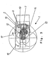
- the device 1 shown in FIGS. 1 to 3 for cutting a strand of material 20 in Disks 23 essentially consist of a cutting device 2, a feed device 3 for the good strand and a receiving device 4 for that of the good strand 20 cut slices 23.
- the cutting device 2 consists of a drive arm 6 which can be driven about an axis of rotation 5.
- a drive arm 6 which can be driven about an axis of rotation 5.
- the Rotation axis 7 of a circular knife 8 which can also be driven in rotation.
- the drive of the drive arm 6 takes place via a hollow shaft 9, which consists of a gearbox flanged to an electric motor 10 11 is brought out.
- the circular knife 8 is driven within the drive arm 6 via a belt drive 12 and further via an arranged within the hollow shaft 9 Knife shaft 13. While the hollow shaft with a compared to the engine speed Rotates factor 10 reduced speed, the motor shaft 13 is at full engine speed operated. For this reason, the circular knife 10 rotates - with a translation of the Belt drive of 1: 1 with ten times the speed of the drive arm 6.
- the hollow shaft 9 and the knife shaft 13 serve the same electric motor 10.
- the circular knife 8 or its outline is different Positions shown.
- Figure 3 is also an envelope 14 of all positions of the Shown like a planet with the drive arm rotating circular knife 8. From Figure 3 leaves it can also be seen that the radius of the circular knife 8 is slightly larger than the radius of the circle 15 on which the axis of rotation 7 of the circular knife 8 moves.
- the feed device 3 is designed in a known manner and has a not shown Gripper hook provided receiving element for the hanging strand 20.
- the Feed device 3 is also provided with a feed shaft 19 which is rectangular in cross section Mistake.
- the material strand 20 is in an end section facing the cutting device 2 can be pressed against a wall of the feed shaft 19 in order to ensure adequate fixation during of the cutting process.
- the receiving device 4 is designed in the form of a conveyor belt 21, of which the Abtrum formed storage surface 22 is arranged inclined relative to the horizontal, that between the lower end face of the crop strand 20 and the storage surface 22 a wedge-shaped gap is formed, in which the drive arm 6 of the cutting device 2 at its Can immerse rotary motion. Due to this inclined orientation of the conveyor belt 21 comes a sufficiently large area part of a disk 23 which is just being created in contact with the shelf 22. This way is before complete separation the disk 23 for a sufficient frictional force between the disk 23 and the storage surface 22 ensures that there is no uncontrolled spinning movement of the disk 23 after whose complete separation can come. Thus in connection with a clocked drive of the conveyor belt 22 an orderly and geometrically accurate shingle storage the discs 23 can be achieved.
- the disk packs picked up by the conveyor belt 21 are not one shown further conveyor to suitable packaging or Acceptance facilities forwarded.
- the device 1 is not only suitable for shingled or shingled storage of Discs 23. Rather, one is then preferably aligned horizontally Holding device also a stacked storage of the panes possible. It is also in the Within the scope of the invention, the device 1 with a vertically movable storage surface provided, the movement of which advantageously with the feed movement of the material strand 20th is synchronized to be constant throughout the cutting process To ensure storage conditions for the cut slices.
Landscapes
- Life Sciences & Earth Sciences (AREA)
- Forests & Forestry (AREA)
- Engineering & Computer Science (AREA)
- Mechanical Engineering (AREA)
- Processing And Handling Of Plastics And Other Materials For Molding In General (AREA)
- Nonmetal Cutting Devices (AREA)
- Preliminary Treatment Of Fibers (AREA)
- Mechanical Treatment Of Semiconductor (AREA)
- Details Of Cutting Devices (AREA)
Claims (5)
- Machine (1) à découper un produit (20) en forme de pain en tranches (23), comprenant un dispositif (2) de coupe, un dispositif (3) d'apport du produit (20) en forme de pain et un dispositif (4) de réception des tranches (23) découpées du produit (20) en forme de pain, le produit (20) en forme de pain pouvant être déplacé au moyen du dispositif (3) d'apport sensiblement verticalement en direction du dispositif (2) de coupe, par lequel il peut être découpé à partir de l'extrémité inférieure du produit (20) en forme de pain dans un plan de coupe sensiblement horizontal des tranches (23), et dans lequel le dispositif (2) de coupe est un couteau (8) circulaire qui peut tourner sur un arbre (6) d'entraínement qui peut être entraíné en rotation et comporte une surface (22) de dépôt, qui reçoit des tranches (23), du dispositif (4) de réception, caractérisée en ce que la surface (22) de dépôt est inclinée par rapport à l'horizontale de façon à former, entre la face frontale inférieure du produit (20) en forme de pain et la surface (22) de dépôt, un intervalle cunéiforme dans lequel pénètre le bras (6) d'entraínement du dispositif (2) de coupe, l'axe (7) de rotation du couteau (8) tournant parcourant lors du mouvement de rotation du bras (6) d'entraínement la section transversale de convoyage du dispositif (3) d'apport.
- Machine suivant la revendication 1, caractérisée en ce que le dispositif (4) de réception est constitué en bandes (21) convoyeuses qui peut être entraíné en cadence et dont la direction de convoyage s'éloigne de l'axe (5) de rotation du bras (6) d'entraínement.
- Machine suivant la revendication 1 ou 2, caractérisée en ce que le bras (6) d'entraínement et le couteau (8) circulaire peuvent être entraínés par un moteur (10) électrique commun.
- Machine suivant l'une des revendications 1 à 3, caractérisée en ce que l'entraínement du bras (6) d'entraínement s'effectue par un arbre (9) creux et l'entraínement du couteau (8) circulaire par un arbre (3) de couteau tournant dans l'arbre (9) creux.
- Machine suivant l'une des revendications 1 à 4, caractérisée en ce que l'entraínement du bras (6) d'entraínement est disposé en dessous du plan de coupe.
Applications Claiming Priority (2)
| Application Number | Priority Date | Filing Date | Title |
|---|---|---|---|
| DE19820269 | 1998-05-07 | ||
| DE19820269A DE19820269C2 (de) | 1998-05-07 | 1998-05-07 | Vorrichtung zum Schneiden eines Gutsstrangs in Scheiben |
Publications (3)
| Publication Number | Publication Date |
|---|---|
| EP0955135A2 EP0955135A2 (fr) | 1999-11-10 |
| EP0955135A3 EP0955135A3 (fr) | 2002-03-06 |
| EP0955135B1 true EP0955135B1 (fr) | 2003-07-09 |
Family
ID=7866876
Family Applications (1)
| Application Number | Title | Priority Date | Filing Date |
|---|---|---|---|
| EP99108048A Expired - Lifetime EP0955135B1 (fr) | 1998-05-07 | 1999-04-23 | Machine à débiter en tranches un produit en forme de pain |
Country Status (3)
| Country | Link |
|---|---|
| EP (1) | EP0955135B1 (fr) |
| AT (1) | ATE244622T1 (fr) |
| DE (2) | DE19820269C2 (fr) |
Families Citing this family (2)
| Publication number | Priority date | Publication date | Assignee | Title |
|---|---|---|---|---|
| DE10004600A1 (de) * | 2000-02-03 | 2001-08-09 | Biforce Anstalt Vaduz | Antriebssystem |
| US8549966B2 (en) | 2007-10-22 | 2013-10-08 | Formax, Inc. | Output conveyor for a food article slicing machine |
Family Cites Families (11)
| Publication number | Priority date | Publication date | Assignee | Title |
|---|---|---|---|---|
| US2227683A (en) * | 1938-09-26 | 1941-01-07 | Ind Patents Corp | Evener and stacker |
| US2414152A (en) * | 1943-05-20 | 1947-01-14 | Aldrich L Jackson | Automatic food slicer and slice counting machine |
| US3867858A (en) * | 1973-07-30 | 1975-02-25 | Gorton Corp | Frozen fish cutter |
| US3842698A (en) * | 1973-09-11 | 1974-10-22 | C Fitch | Slicing machine for slicing a food product or the like |
| DE2351980A1 (de) * | 1973-10-17 | 1975-04-30 | Hans Neuner | Abschneidevorrichtung fuer speckschneider und aehnliche schneidemaschinen |
| US3972256A (en) * | 1975-05-30 | 1976-08-03 | Ross Henry M | Meat slicer |
| US4177703A (en) * | 1978-04-17 | 1979-12-11 | Cavier Adolf J J F | Slicing machine for salmon |
| DK195284A (da) * | 1984-04-16 | 1985-10-17 | Newmac A S | Skaeremaskine til opskaering af blokke, isaer foedevareblokke i skiver |
| US4685364A (en) * | 1985-05-17 | 1987-08-11 | Bettcher Industries, Inc. | Rotary slicer for comestible products |
| DE4220602C2 (de) * | 1992-04-29 | 2001-02-22 | Maschb Heinrich Hajek Gmbh & C | Schneidemaschine zum Schneiden von Lebensmittelprodukten mit längenverstellbarem Transportband |
| DE4421116C1 (de) * | 1994-06-16 | 1995-07-13 | Uwe Reifenhaeuser | Verfahren und Vorrichtung zum Stapeln und Abtransportieren von in Scheiben geschnittenem Stranggut |
-
1998
- 1998-05-07 DE DE19820269A patent/DE19820269C2/de not_active Expired - Fee Related
-
1999
- 1999-04-23 EP EP99108048A patent/EP0955135B1/fr not_active Expired - Lifetime
- 1999-04-23 AT AT99108048T patent/ATE244622T1/de active
- 1999-04-23 DE DE59906232T patent/DE59906232D1/de not_active Expired - Lifetime
Also Published As
| Publication number | Publication date |
|---|---|
| HK1024439A1 (en) | 2000-10-13 |
| DE19820269A1 (de) | 1999-11-11 |
| EP0955135A2 (fr) | 1999-11-10 |
| ATE244622T1 (de) | 2003-07-15 |
| DE59906232D1 (de) | 2003-08-14 |
| EP0955135A3 (fr) | 2002-03-06 |
| DE19820269C2 (de) | 2000-06-21 |
Similar Documents
| Publication | Publication Date | Title |
|---|---|---|
| EP0955137B1 (fr) | Machine à débiter en tranches | |
| EP2045053B1 (fr) | Machine de découpe à disques pour aliments en forme de tronçons | |
| EP0248354A2 (fr) | Trancheuse | |
| EP0244003B1 (fr) | Dispositif d'empilage de produits en forme de bande repliés en zigzag | |
| DE2444206B2 (de) | Verfahren und Vorrichtung zum kreuzweisen Stapeln von Bögen aus Papier o.dgl | |
| DE9313637U1 (de) | Schneidmaschine für Brot | |
| DE3734844A1 (de) | Bewegbare stapelvorrichtung fuer eine maschine zum aufschneiden laibfoermiger lebensmittel | |
| DE10043304A1 (de) | Vorrichtung zum Auslegen von Wurst- oder dergleichen Lebensmittelscheiben | |
| EP1094717B1 (fr) | Dispositif pour separer des morceaux individuels d'un boudin de matiere deplace en continu | |
| DE3330681C2 (fr) | ||
| EP2894016A1 (fr) | Dispositif et procédé pour la coupe de produits alimentaires | |
| DE3644716A1 (de) | Verfahren und vorrichtung zum schneiden und ablegen von lebensmitteln | |
| EP2200791B1 (fr) | Dispositif de réception et d'évacuation de produit coupé alimentaire, et trancheuse de produit alimentaire | |
| EP0776740A1 (fr) | Dispositif et méthode pour déposer des produits alimentaires découpés en tranches sur un moyen de transport | |
| EP0955135B1 (fr) | Machine à débiter en tranches un produit en forme de pain | |
| DE2153065C3 (de) | Aufschnittschneidemaschine | |
| EP0634325A1 (fr) | Dispositif pour arranger des articles coupés en les répartissant comme des bardeaux | |
| DE102009019430A1 (de) | Umleger für automatische Scheibenschneidemaschinen | |
| EP1938932B1 (fr) | Machine destinée à couper des produits alimentaires en forme de tronçon en rondelles, ainsi que procédé de coupe | |
| EP2140988B1 (fr) | Machine à découper des aliments et procédé de dépôt et de transport de tranches de produits à découper | |
| EP0673729A1 (fr) | Dispositif pour la coupe de produits imprimés | |
| WO2001007215A1 (fr) | Procede et dispositif pour deposer des produits de maniere irreguliere | |
| DE29720348U1 (de) | Aufschneidemaschine für Lebensmittelriegel | |
| DE3801492A1 (de) | Vorrichtung zum abschneiden von einzelstuecken von einem massestrang | |
| DE102022108452A1 (de) | Verfahren zum Schneiden eines Lebensmittels in Scheiben sowie Schneidvorrichtung |
Legal Events
| Date | Code | Title | Description |
|---|---|---|---|
| PUAI | Public reference made under article 153(3) epc to a published international application that has entered the european phase |
Free format text: ORIGINAL CODE: 0009012 |
|
| AK | Designated contracting states |
Kind code of ref document: A2 Designated state(s): AT BE CH CY DE DK ES FI FR GB GR IE IT LI LU MC NL PT SE Kind code of ref document: A2 Designated state(s): AT BE CH DE FR GB LI NL |
|
| AX | Request for extension of the european patent |
Free format text: AL;LT;LV;MK;RO;SI |
|
| PUAL | Search report despatched |
Free format text: ORIGINAL CODE: 0009013 |
|
| AK | Designated contracting states |
Kind code of ref document: A3 Designated state(s): AT BE CH CY DE DK ES FI FR GB GR IE IT LI LU MC NL PT SE |
|
| AX | Request for extension of the european patent |
Free format text: AL;LT;LV;MK;RO;SI |
|
| RIC1 | Information provided on ipc code assigned before grant |
Free format text: 7B 26D 7/06 A, 7B 26D 1/16 B, 7B 26D 7/32 B, 7A 47J 37/07 B |
|
| 17P | Request for examination filed |
Effective date: 20020809 |
|
| AKX | Designation fees paid |
Free format text: AT BE CH DE FR GB LI NL |
|
| GRAH | Despatch of communication of intention to grant a patent |
Free format text: ORIGINAL CODE: EPIDOS IGRA |
|
| GRAH | Despatch of communication of intention to grant a patent |
Free format text: ORIGINAL CODE: EPIDOS IGRA |
|
| GRAA | (expected) grant |
Free format text: ORIGINAL CODE: 0009210 |
|
| AK | Designated contracting states |
Designated state(s): AT BE CH DE FR GB LI NL |
|
| REG | Reference to a national code |
Ref country code: GB Ref legal event code: FG4D Free format text: NOT ENGLISH |
|
| REG | Reference to a national code |
Ref country code: CH Ref legal event code: EP |
|
| REF | Corresponds to: |
Ref document number: 59906232 Country of ref document: DE Date of ref document: 20030814 Kind code of ref document: P |
|
| REG | Reference to a national code |
Ref country code: IE Ref legal event code: FG4D Free format text: GERMAN |
|
| GBT | Gb: translation of ep patent filed (gb section 77(6)(a)/1977) |
Effective date: 20031112 |
|
| REG | Reference to a national code |
Ref country code: CH Ref legal event code: NV Representative=s name: OK PAT AG PATENTE MARKEN LIZENZEN |
|
| REG | Reference to a national code |
Ref country code: IE Ref legal event code: FD4D |
|
| ET | Fr: translation filed | ||
| PLBE | No opposition filed within time limit |
Free format text: ORIGINAL CODE: 0009261 |
|
| STAA | Information on the status of an ep patent application or granted ep patent |
Free format text: STATUS: NO OPPOSITION FILED WITHIN TIME LIMIT |
|
| 26N | No opposition filed |
Effective date: 20040414 |
|
| REG | Reference to a national code |
Ref country code: CH Ref legal event code: PCAR Free format text: ALDO ROEMPLER PATENTANWALT;BRENDENWEG 11 POSTFACH 154;9424 RHEINECK (CH) |
|
| REG | Reference to a national code |
Ref country code: FR Ref legal event code: PLFP Year of fee payment: 17 |
|
| PGFP | Annual fee paid to national office [announced via postgrant information from national office to epo] |
Ref country code: DE Payment date: 20150430 Year of fee payment: 17 Ref country code: GB Payment date: 20150430 Year of fee payment: 17 Ref country code: CH Payment date: 20150427 Year of fee payment: 17 |
|
| PGFP | Annual fee paid to national office [announced via postgrant information from national office to epo] |
Ref country code: AT Payment date: 20150428 Year of fee payment: 17 Ref country code: FR Payment date: 20150430 Year of fee payment: 17 Ref country code: NL Payment date: 20150424 Year of fee payment: 17 Ref country code: BE Payment date: 20150429 Year of fee payment: 17 |
|
| PG25 | Lapsed in a contracting state [announced via postgrant information from national office to epo] |
Ref country code: BE Free format text: LAPSE BECAUSE OF NON-PAYMENT OF DUE FEES Effective date: 20160430 |
|
| REG | Reference to a national code |
Ref country code: DE Ref legal event code: R119 Ref document number: 59906232 Country of ref document: DE |
|
| REG | Reference to a national code |
Ref country code: CH Ref legal event code: PL |
|
| REG | Reference to a national code |
Ref country code: NL Ref legal event code: MM Effective date: 20160501 |
|
| REG | Reference to a national code |
Ref country code: AT Ref legal event code: MM01 Ref document number: 244622 Country of ref document: AT Kind code of ref document: T Effective date: 20160423 |
|
| GBPC | Gb: european patent ceased through non-payment of renewal fee |
Effective date: 20160423 |
|
| REG | Reference to a national code |
Ref country code: FR Ref legal event code: ST Effective date: 20161230 |
|
| PG25 | Lapsed in a contracting state [announced via postgrant information from national office to epo] |
Ref country code: FR Free format text: LAPSE BECAUSE OF NON-PAYMENT OF DUE FEES Effective date: 20160502 Ref country code: LI Free format text: LAPSE BECAUSE OF NON-PAYMENT OF DUE FEES Effective date: 20160430 Ref country code: NL Free format text: LAPSE BECAUSE OF NON-PAYMENT OF DUE FEES Effective date: 20160501 Ref country code: CH Free format text: LAPSE BECAUSE OF NON-PAYMENT OF DUE FEES Effective date: 20160430 Ref country code: GB Free format text: LAPSE BECAUSE OF NON-PAYMENT OF DUE FEES Effective date: 20160423 Ref country code: DE Free format text: LAPSE BECAUSE OF NON-PAYMENT OF DUE FEES Effective date: 20161101 |
|
| PG25 | Lapsed in a contracting state [announced via postgrant information from national office to epo] |
Ref country code: AT Free format text: LAPSE BECAUSE OF NON-PAYMENT OF DUE FEES Effective date: 20160423 |