EP2894016A1 - Dispositif et procédé pour la coupe de produits alimentaires - Google Patents
Dispositif et procédé pour la coupe de produits alimentaires Download PDFInfo
- Publication number
- EP2894016A1 EP2894016A1 EP14194959.4A EP14194959A EP2894016A1 EP 2894016 A1 EP2894016 A1 EP 2894016A1 EP 14194959 A EP14194959 A EP 14194959A EP 2894016 A1 EP2894016 A1 EP 2894016A1
- Authority
- EP
- European Patent Office
- Prior art keywords
- product
- cutting
- feed
- axis
- longitudinal axis
- Prior art date
- Legal status (The legal status is an assumption and is not a legal conclusion. Google has not performed a legal analysis and makes no representation as to the accuracy of the status listed.)
- Withdrawn
Links
Images


Classifications
-
- B—PERFORMING OPERATIONS; TRANSPORTING
- B26—HAND CUTTING TOOLS; CUTTING; SEVERING
- B26D—CUTTING; DETAILS COMMON TO MACHINES FOR PERFORATING, PUNCHING, CUTTING-OUT, STAMPING-OUT OR SEVERING
- B26D7/00—Details of apparatus for cutting, cutting-out, stamping-out, punching, perforating, or severing by means other than cutting
- B26D7/06—Arrangements for feeding or delivering work of other than sheet, web, or filamentary form
-
- B—PERFORMING OPERATIONS; TRANSPORTING
- B26—HAND CUTTING TOOLS; CUTTING; SEVERING
- B26D—CUTTING; DETAILS COMMON TO MACHINES FOR PERFORATING, PUNCHING, CUTTING-OUT, STAMPING-OUT OR SEVERING
- B26D1/00—Cutting through work characterised by the nature or movement of the cutting member or particular materials not otherwise provided for; Apparatus or machines therefor; Cutting members therefor
- B26D1/01—Cutting through work characterised by the nature or movement of the cutting member or particular materials not otherwise provided for; Apparatus or machines therefor; Cutting members therefor involving a cutting member which does not travel with the work
- B26D1/12—Cutting through work characterised by the nature or movement of the cutting member or particular materials not otherwise provided for; Apparatus or machines therefor; Cutting members therefor involving a cutting member which does not travel with the work having a cutting member moving about an axis
- B26D1/14—Cutting through work characterised by the nature or movement of the cutting member or particular materials not otherwise provided for; Apparatus or machines therefor; Cutting members therefor involving a cutting member which does not travel with the work having a cutting member moving about an axis with a circular cutting member, e.g. disc cutter
- B26D1/157—Cutting through work characterised by the nature or movement of the cutting member or particular materials not otherwise provided for; Apparatus or machines therefor; Cutting members therefor involving a cutting member which does not travel with the work having a cutting member moving about an axis with a circular cutting member, e.g. disc cutter rotating about a movable axis
-
- B—PERFORMING OPERATIONS; TRANSPORTING
- B26—HAND CUTTING TOOLS; CUTTING; SEVERING
- B26D—CUTTING; DETAILS COMMON TO MACHINES FOR PERFORATING, PUNCHING, CUTTING-OUT, STAMPING-OUT OR SEVERING
- B26D7/00—Details of apparatus for cutting, cutting-out, stamping-out, punching, perforating, or severing by means other than cutting
- B26D7/01—Means for holding or positioning work
-
- B—PERFORMING OPERATIONS; TRANSPORTING
- B26—HAND CUTTING TOOLS; CUTTING; SEVERING
- B26D—CUTTING; DETAILS COMMON TO MACHINES FOR PERFORATING, PUNCHING, CUTTING-OUT, STAMPING-OUT OR SEVERING
- B26D7/00—Details of apparatus for cutting, cutting-out, stamping-out, punching, perforating, or severing by means other than cutting
- B26D7/06—Arrangements for feeding or delivering work of other than sheet, web, or filamentary form
- B26D7/0683—Arrangements for feeding or delivering work of other than sheet, web, or filamentary form specially adapted for elongated articles
-
- B—PERFORMING OPERATIONS; TRANSPORTING
- B26—HAND CUTTING TOOLS; CUTTING; SEVERING
- B26D—CUTTING; DETAILS COMMON TO MACHINES FOR PERFORATING, PUNCHING, CUTTING-OUT, STAMPING-OUT OR SEVERING
- B26D7/00—Details of apparatus for cutting, cutting-out, stamping-out, punching, perforating, or severing by means other than cutting
- B26D7/26—Means for mounting or adjusting the cutting member; Means for adjusting the stroke of the cutting member
- B26D7/2628—Means for adjusting the position of the cutting member
-
- B—PERFORMING OPERATIONS; TRANSPORTING
- B26—HAND CUTTING TOOLS; CUTTING; SEVERING
- B26D—CUTTING; DETAILS COMMON TO MACHINES FOR PERFORATING, PUNCHING, CUTTING-OUT, STAMPING-OUT OR SEVERING
- B26D7/00—Details of apparatus for cutting, cutting-out, stamping-out, punching, perforating, or severing by means other than cutting
- B26D7/01—Means for holding or positioning work
- B26D2007/013—Means for holding or positioning work the work being tubes, rods or logs
-
- B—PERFORMING OPERATIONS; TRANSPORTING
- B26—HAND CUTTING TOOLS; CUTTING; SEVERING
- B26D—CUTTING; DETAILS COMMON TO MACHINES FOR PERFORATING, PUNCHING, CUTTING-OUT, STAMPING-OUT OR SEVERING
- B26D2210/00—Machines or methods used for cutting special materials
- B26D2210/02—Machines or methods used for cutting special materials for cutting food products, e.g. food slicers
-
- Y—GENERAL TAGGING OF NEW TECHNOLOGICAL DEVELOPMENTS; GENERAL TAGGING OF CROSS-SECTIONAL TECHNOLOGIES SPANNING OVER SEVERAL SECTIONS OF THE IPC; TECHNICAL SUBJECTS COVERED BY FORMER USPC CROSS-REFERENCE ART COLLECTIONS [XRACs] AND DIGESTS
- Y10—TECHNICAL SUBJECTS COVERED BY FORMER USPC
- Y10T—TECHNICAL SUBJECTS COVERED BY FORMER US CLASSIFICATION
- Y10T83/00—Cutting
- Y10T83/04—Processes
-
- Y—GENERAL TAGGING OF NEW TECHNOLOGICAL DEVELOPMENTS; GENERAL TAGGING OF CROSS-SECTIONAL TECHNOLOGIES SPANNING OVER SEVERAL SECTIONS OF THE IPC; TECHNICAL SUBJECTS COVERED BY FORMER USPC CROSS-REFERENCE ART COLLECTIONS [XRACs] AND DIGESTS
- Y10—TECHNICAL SUBJECTS COVERED BY FORMER USPC
- Y10T—TECHNICAL SUBJECTS COVERED BY FORMER US CLASSIFICATION
- Y10T83/00—Cutting
- Y10T83/647—With means to convey work relative to tool station
- Y10T83/6572—With additional mans to engage work and orient it relative to tool station
Definitions
- the present invention relates to a device, in particular Hochadosslicer, for slicing food products such as in particular sausage, cheese, ham and / or the like, with a product feed, which feeds a product Techschnendes a cutting plane in which a cutting blade adjacent to a cutting edge in particular rotating and / or planetary orbiting moves. It further relates to a method for slicing food products specified in the preamble of claim 14 Art.
- Automatic cutting devices for food products are well known. They usually include a circular or sickle blade, a product feeder with a cutting edge, which may be formed as a breakthrough cutting glasses, as a knife-side conclusion and a storage surface such as a Portionierband or the like for storing the separated product slices and portioning.
- the product feeder and the cutting blade are at a right angle to each other and also during the slicing operation in a fixed position, so that the product feeder or its conveying devices such as product holder and / or hold always cause an advance in the direction of the cutting blade. If necessary, the product can also be moved in the opposite direction and withdrawn, for example, for idle cuts.
- the invention is therefore an object of the invention to provide an apparatus and a method of the type mentioned, with which also irregular parts of the product can be easily produced and / or shingling can be achieved in the stacking of sliced product slices.
- this object is achieved according to the invention in that means are provided for rotating the product fed to the cutting plane at least over a predefinable angular range about an axis during the slicing operation.
- the product feed is rotatable and the product rotatable about the product feed about the axis of rotation.
- the product in the product feed is fixable so that it is entrained in a rotation of the product supply of this, at the same time the feed of the product is ensured in the direction of the cutting plane.
- both the product feed and the cutting edge are each rotatable about the axis of rotation. This ensures that the product to be sliced is always reliably supported on the cutting edge, regardless of the particular rotational position during cutting.
- the product feeder and the cutting edge are rotatable in the same direction.
- the product feed and the cutting edge can in particular be rotatable together about the axis of rotation.
- the product feed and the cutting edge can rotate at the same speed or at different speeds.
- the cutting edge is rotatable at a lower speed about the axis of rotation than the product feed.
- the product feed and the cutting edge are preferably coupled to one another mechanically and / or on the drive side.
- the product feed and the cutting edge can be rotatable in the same direction or in the opposite direction.
- such an embodiment of the cutting device according to the invention is conceivable in which the cutting edge is dragged by the rotating product.
- the product feed and the cutting edge can also be coupled mechanically or on the drive side.
- the drives are expediently synchronized in this case.
- the product feed and the cutting edge are rotatable in the opposite direction, they can be coupled in particular mechanically and / or drive side.
- the cutting edge is rotatably mounted. In this case, only the product feed rotates and the product to be sliced accordingly.
- the product to be sliced can be fed vertically or obliquely to the cutting plane. It is particularly advantageous if the feed direction in which the product to be sliced is fed to the cutting plane through the product feed is variably adjustable relative to the normal of the cutting plane.
- the feed direction in which the product to be sliced is fed to the cutting plane through the product feed during the slicing operation relative to the normal of the cutting plane vary.
- the sliced product to be cut can be fed by the product feed during the slicing operation relative to the normal of the cutting plane, e.g. be pivoted in a plane, in particular in the horizontal and / or vertical direction.
- the product can be caused to move in a kind of wobbling motion, for example by moving the product in such a way that the longitudinal axis of the product describes a conical surface by means of the product feed.
- the product additionally rotates about the axis of rotation, e.g. coincides with the product longitudinal axis.
- a tumbling motion of the product may be achieved by rotating the product about an axis of rotation that does not coincide with the product longitudinal axis.
- the product feed can be rotated together with the product to be sliced by 360 ° or even over an angular range less than 360 ° about the longitudinal axis of the product.
- the product feed can be drivable together with the product to be sliced, in particular for a weighing movement about the axis of rotation, ie the product feed and product moves alternately in one and in the opposite direction of rotation, relative to a basically arbitrary reference angular position by the same or different angular amounts.
- the product feed can be driven together with the product to be cut to a varying weighing movement over a changing angle range about the axis of rotation. This way, a particularly strong Irregularity of the product separated parts, in particular with respect to a variation of the thickness of the sliced product slices, can be achieved.
- the product to be sliced can be fed by the product feed the cutting plane, for example, in a different direction from their normal direction.
- a kind of sniping cut can be produced, whereby the severed parts can vary in thickness from one edge to the other.
- the speed at which the product is supplied to the cutting plane can also influence the areal size of the separated parts or snippets are taken because because of the oblique employment of the product with respect to the cutting plane with the thickness of the parts or snippets and their cutting surface increases.
- the product to be sliced can be fed to the cutting plane with a variable setting angle during the slicing operation.
- the product supply can thus be pivoted during the slicing operation while maintaining the rotation about the longitudinal axis of the product in particular light in the horizontal and / or vertical direction, resulting in different parts or snippets and Portionsformen.
- the rotational speed of the product feed, the direction of rotation of the product feed, the feed rate, the direction of rotation of the cutting blade and / or the speed of the cutting blade are variably adjustable, which sizes can at least partially vary again during the slicing operation.
- the product feed and the cutting blade may be rotatable in the same direction or in the opposite direction.
- a rotation of the product feed and the cutting blade in the same direction is particularly advantageous for non-cylindrical products.
- the rotatably mounted product feed preferably has an at least substantially closed contour, which ensures that the product to be sliced is sufficiently fixable in the product feed and is taken along accordingly and thereby set in rotation.
- each track then preferably has an independently mounted and driven product feeder.
- the cutting edge may have a circumferentially open, semi-open or closed contour. Preferably, it is always aligned parallel to the cutting plane.
- the cutting edge comprises at least one wall or opening facing the product feed, which corresponds to the inclination the product supply is employed with respect to the cutting plane to the product feed side facing or expands.
- the surfaces of the cutting edge lying in the direction of the cutting force or the main printing direction of the knife are adapted to possible angles of attack of the product feed. This results in a better investment of réellemolden product at angled employee product feed.
- the portions produced by means of the cutting device according to the invention are particularly suitable as an irregular, preferably scatterable coating or as an ingredient for dishes, e.g. for filling baked goods, salads or pizza toppings.
- fresh meat which is to be provided for corresponding dishes in snippets for frying, can be pre-cut quickly and in large quantities.
- a method for slicing food products such as in particular sausage, cheese, ham and / or the like by means of a cutting device, in particular a Hochadosslicers, in which a product to be cut is fed to a cutting plane in which a cutting blade is moved adjacent to a cutting edge in particular rotating and / or planetary circumferential, wherein the cutting plane supplied product during the slicing operation is rotated at least over a predetermined angular range about an axis, in particular about a longitudinal axis of the product in rotation.
- a cutting device according to the invention is used in this method.
- Fig. 1 shows a schematic representation of an exemplary embodiment of a device 10 according to the invention, in particular a Hochadosslicers, for slicing food products such as sausage, cheese, ham and / or the like.
- the cutting device 10 comprises a product feed 12, which has a product 14 to be cut on a cutting plane 16 (cf. Fig. 3 ), in which a cutting blade 18 designed here as a sickle blade moves in a manner of rotation about a knife axis 28 adjacent to a cutting edge 20.
- the product feeder 12 may contain the usual components such as a product support, one at the rear Have product end attacking product holder and optionally other or other conveyors such as traction belts.
- the cutting device 10 comprises means for rotating the product 14 fed to the cutting plane 16 during the slicing operation at least over a predefinable angular range about a longitudinal axis L of the product 14 parallel to the feed direction Z.
- the product feeder 12 is preferably designed to be rotatable and thus the product 14 by means of the product feed 12 about its longitudinal axis L rotatable.
- the direction of rotation of the product 14 is indicated in each case by an arrow 22.
- Both the product feed 12 and the cutting edge 20 can each be rotatable about the longitudinal axis L of the product 14, wherein the product feed 12 and the cutting edge 20 are preferably rotatable in the same direction.
- the product feed 12 and the cutting edge 20 may in particular be rotatable together about the longitudinal axis L of the product 14, for which purpose they may be coupled in particular mechanically or on the drive side.
- the cutting edge 20 is rotatable at a lower speed about the longitudinal axis L of the product 14 than the product feed 12.
- the product feed 12 and the cutting edge 20 again correspondingly mechanically or coupled on the drive side.
- the cutting edge 20 may also be rotatably mounted so that only the product feed 12 and with this the product 12 rotate.
- the product to be sliced 14 can by means of the product feed 12 of the cutting plane 16 at a right angle or in a normal to their 24 (see. Fig. 3 ) deviating direction be fed.
- Fig. 2a and 2b show a multi-track variant of the invention.
- a product gripper 30 cooperating with the rear product end is provided as a product feed and a cylindrical product feed 12.
- the common cutting edge 20, which cooperates with the cutting blade, not shown, is provided with openings 32 for the products 14.
- Fig. 2a the product is fed perpendicular to the cutting plane 16.
- the top view of Fig. 2b shows that an oblique product supply, ie a deviating from 90 ° angle of attack, is possible. This will be described below in connection with Fig. 3 discussed in more detail.
- the double arrows in Fig. 2 indicate in each case that the angle of attack can be varied.
- the products 14 are rotating about their longitudinal axis L, they can be pivoted back and forth during cutting at a varying angle of attack and thus caused to oscillate in a horizontal plane.
- the walls of the openings 32 of the cutting edge 20 are chamfered accordingly.
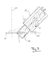
- Fig. 3 shows a schematic plan view of a track of a cutting device according to the invention, wherein in the present case, the feed direction Z, in which the Product 14 of the cutting plane 16 is supplied to the cutting plane 16 is employed and forms an angle ⁇ with the normal 24.
- the feeding direction Z in which the product 14 to be sliced is fed to the cutting plane 16 through the product feed 12, can be variably adjustable relative to the normal 24 of the cutting plane 16 and vary during the slicing operation relative to the normal 24 of the cutting plane 16.
- the cutting plane 16 supplied sliced product 14 by the product feed 12 during the slicing operation relative to the normal 24 of the cutting plane 16 in particular in the horizontal and / or vertical direction can be pivoted.
- the product 14 can also be caused to wobble.
- Fig. 3 is a horizontal pendulum motion of the product 14 each at an angle ⁇ to both sides of an in Fig. 3 Indicated by the product longitudinal axis L neutral position indicated, namely about a pivot point 34.
- the position of this pivot point 34 can basically be chosen arbitrarily.
- the neutral position can also be selected such that the product longitudinal axis L runs in the neutral position parallel to the normal 24 of the cutting plane 16.
- the pivot point 34 may define the tip of a cone, on the lateral surface of which the product central axis L revolves and whose opening angle is equal to the angle ⁇ .
- the pendulum or wobble angle ⁇ must be neither spatially symmetrical with respect to a neutral position nor constant in time, ie a spatial and / or temporal variation of the pendulum or wobble motion represents a further possibility offered by the invention, a particularly high degree of irregularity of From the product 14 separated parts or snippets to achieve.
- Fig. 3 is the product 14 by means of the product feed 12 about its longitudinal axis L in rotation displaceable, ie the axis of rotation and the product longitudinal axis L coincide here and also parallel to the feed direction Z of the product 14.
- this is not mandatory, ie According to the invention, these directions or axes can also fall apart in order to achieve a respectively desired resulting orientation or movement of the front product end, from which parts or chips are separated by means of the cutting blade, not shown.
- the rotatably mounted and displaceable by a corresponding drive in rotation product supply 12 may have an at least substantially closed contour, so that the réellebede product 14 is fixed relative to the rotatable product supply 12 and thus can be set by this in rotation.
- the product feed 12 can be rotatable together with the product 14 to be cut by 360 ° or only over an angular range of less than 360 ° about the longitudinal axis L of the product 14.
- the product feed 12 can be drivable together with the product to be sliced 14 in particular to a weighing movement about the longitudinal axis L of the product 14, ie the product 14 performs no complete rotations, but each rotational movements of less than 360 ° alternately in the one and in the other direction of rotation.
- the cutting device 10 is conceivable in which the product feed 12 can be driven during the slicing operation together with the product 14 to be sliced to a varying weighing movement over a changing angular range about the longitudinal axis L of the product 14.
- the product 14 to be sliced can be deliverable to the cutting plane with a variable angle of attack ⁇ during the slicing operation.
- ⁇ angle of attack
- such an embodiment of the cutting device 10 is conceivable in which the product 14 to be sliced through the product feed 12 of the cutting plane 16 in a deviating from their normal 24 constant direction can be fed.
- the cutting edge 20 may have an open or closed contour in the circumferential direction. In the latter case, the cutting edge has one or more openings for one or more simultaneously réelleelle products and is also referred to as "cutting glasses" (see, eg Fig. 2a ).
- the cutting edge 20 is designed in the form of an angle piece which, for example, forms a right angle, so that a product 14 which is rectangular in cross-section, for example, abuts the cutting edge 20 on two adjoining sides.
- a product 14 which is rectangular in cross-section, for example, abuts the cutting edge 20 on two adjoining sides.
- the product 14 can not fall out of a correspondingly cross-sectionally rectangular and thus trough-like product receptacle, ie it is then not necessary to completely cover the product over the entire circumference.
- the cutting edge 20 is aligned parallel to the cutting plane 16.
- the cutting edge 20 may include at least one of the product feed 12 facing wall 26 or opening, which is employed in an oblique feed of the sliced product 14 to the cutting plane 16 to the product feed 12 side facing or expands.
- the product feeder 12 may be rotatable in the same direction as the cutting blade 18.
- the cutting device 10 is conceivable in which the product feeder 12 and the cutting blade 18 are rotatable in opposite directions.
- the rotational speed of the product feeder 12, the direction of rotation of the product feeder 12, the feed rate, the direction of rotation of the cutting blade 18 and / or the speed of the cutting blade 18 can be variably adjusted. These parameters may also vary during the slicing operation or be variably adjustable.
- the product feed 12 and, if appropriate, the cutting edge 20 or its drive or drives can be assigned to an electronic control device via which they can be correspondingly controlled and / or regulated.
- a stack or shingling with irregular edge offset results when the sliced product slices or product parts are deposited.
- heaped portions of chip parts with more or less strong irregularity and sections in particular varying size, thickness and / or format can be formed.
- the portions thus produced or snippet-like portions produced continuously without portioning are particularly suitable as irregular ones, preferably Streubarer coating or as an ingredient for dishes such as for covering baked goods, for salads or pizza toppings.
- irregular ones preferably Streubarer coating or as an ingredient for dishes such as for covering baked goods, for salads or pizza toppings.
- fresh meat which is to be provided for corresponding dishes in schnipseln for searing, be pre-cut quickly and in large quantities.
Landscapes
- Life Sciences & Earth Sciences (AREA)
- Forests & Forestry (AREA)
- Engineering & Computer Science (AREA)
- Mechanical Engineering (AREA)
- Formation And Processing Of Food Products (AREA)
- Confectionery (AREA)
Applications Claiming Priority (1)
| Application Number | Priority Date | Filing Date | Title |
|---|---|---|---|
| DE102014100159.1A DE102014100159A1 (de) | 2014-01-08 | 2014-01-08 | Vorrichtung und Verfahren zum Aufschneiden von Lebensmittelprodukten |
Publications (1)
| Publication Number | Publication Date |
|---|---|
| EP2894016A1 true EP2894016A1 (fr) | 2015-07-15 |
Family
ID=51987042
Family Applications (1)
| Application Number | Title | Priority Date | Filing Date |
|---|---|---|---|
| EP14194959.4A Withdrawn EP2894016A1 (fr) | 2014-01-08 | 2014-11-26 | Dispositif et procédé pour la coupe de produits alimentaires |
Country Status (3)
| Country | Link |
|---|---|
| US (1) | US20150190939A1 (fr) |
| EP (1) | EP2894016A1 (fr) |
| DE (1) | DE102014100159A1 (fr) |
Families Citing this family (5)
| Publication number | Priority date | Publication date | Assignee | Title |
|---|---|---|---|---|
| DE102017112177B4 (de) * | 2017-06-02 | 2023-11-23 | Tvi Entwicklung Und Produktion Gmbh | Schneideinheit sowie Schneidverfahren |
| US11059197B2 (en) * | 2017-08-24 | 2021-07-13 | Cozzini Llc | Method of slicing a food item and slicing mechanism employing a gripping element that generates a vacuum grip |
| US11825854B2 (en) * | 2018-12-13 | 2023-11-28 | Geunyoung YI | Fixed-quantity meat slicer for chilled meat |
| US20230125230A1 (en) | 2021-10-25 | 2023-04-27 | Provisur Technologies, Inc. | Pivoting loading tray assembly for food product slicing apparatus and method of use |
| DE102022108508A1 (de) * | 2022-04-08 | 2023-10-12 | Multivac Sepp Haggenmüller Se & Co. Kg | Aufschneide-Maschine mit Sprüh-Einheit |
Citations (6)
| Publication number | Priority date | Publication date | Assignee | Title |
|---|---|---|---|---|
| DE19756694A1 (de) * | 1997-12-19 | 1999-06-24 | Holger Uhrig | Verfahren zur Herstellung eines in einzelne Scheiben trennbaren Produktes |
| DE20310219U1 (de) * | 2003-07-03 | 2003-09-04 | Spiekermann, Herbert, 59757 Arnsberg | Schneidemaschine für Lebensmittel |
| JP2004090115A (ja) * | 2002-08-30 | 2004-03-25 | Yoshiizumi Sangyo Kk | 食品スライス装置 |
| DE19837645B4 (de) | 1998-08-19 | 2008-04-10 | Weber Maschinenbau Gmbh & Co. Kg | Vorrichtung und Verfahren zum Schneiden von Lebensmittelprodukten |
| DE19837644B4 (de) | 1998-08-19 | 2008-04-10 | Weber Maschinenbau Gmbh & Co. Kg | Vorrichtung und Verfahren zum Schneiden von Lebensmittelprodukten |
| JP2010167526A (ja) * | 2009-01-22 | 2010-08-05 | Emura Tekkosho:Kk | フードスライサー |
Family Cites Families (8)
| Publication number | Priority date | Publication date | Assignee | Title |
|---|---|---|---|---|
| US1809764A (en) * | 1927-09-22 | 1931-06-09 | Trunz Max | Bias bacon slicer |
| US5558011A (en) * | 1995-09-05 | 1996-09-24 | Heim; Stephen J. | Fruit paring and cutting apparatus |
| US6053098A (en) * | 1999-09-17 | 2000-04-25 | Benriner Co., Ltd. | Rotary root vegetable slicer |
| TW595386U (en) * | 2003-06-25 | 2004-06-21 | Jia-Jiu Wang | Improved peeler |
| FR2909916B1 (fr) * | 2006-12-13 | 2009-03-06 | Kaufler Soc Par Actions Simpli | "dispositif de decoupe de produits alimentaires a moyens de tranchage multiples" |
| JP2009005645A (ja) * | 2007-06-29 | 2009-01-15 | Yoshiizumi Sangyo Kk | 食品切分け装置 |
| JP5099837B2 (ja) * | 2008-01-31 | 2012-12-19 | 吉泉産業株式会社 | 材料のスライス方法及びスライス装置 |
| JP5124883B2 (ja) * | 2009-02-13 | 2013-01-23 | 株式会社日本キャリア工業 | 食肉スライサー |
-
2014
- 2014-01-08 DE DE102014100159.1A patent/DE102014100159A1/de not_active Withdrawn
- 2014-11-26 EP EP14194959.4A patent/EP2894016A1/fr not_active Withdrawn
- 2014-12-19 US US14/577,370 patent/US20150190939A1/en not_active Abandoned
Patent Citations (6)
| Publication number | Priority date | Publication date | Assignee | Title |
|---|---|---|---|---|
| DE19756694A1 (de) * | 1997-12-19 | 1999-06-24 | Holger Uhrig | Verfahren zur Herstellung eines in einzelne Scheiben trennbaren Produktes |
| DE19837645B4 (de) | 1998-08-19 | 2008-04-10 | Weber Maschinenbau Gmbh & Co. Kg | Vorrichtung und Verfahren zum Schneiden von Lebensmittelprodukten |
| DE19837644B4 (de) | 1998-08-19 | 2008-04-10 | Weber Maschinenbau Gmbh & Co. Kg | Vorrichtung und Verfahren zum Schneiden von Lebensmittelprodukten |
| JP2004090115A (ja) * | 2002-08-30 | 2004-03-25 | Yoshiizumi Sangyo Kk | 食品スライス装置 |
| DE20310219U1 (de) * | 2003-07-03 | 2003-09-04 | Spiekermann, Herbert, 59757 Arnsberg | Schneidemaschine für Lebensmittel |
| JP2010167526A (ja) * | 2009-01-22 | 2010-08-05 | Emura Tekkosho:Kk | フードスライサー |
Also Published As
| Publication number | Publication date |
|---|---|
| US20150190939A1 (en) | 2015-07-09 |
| DE102014100159A1 (de) | 2015-07-23 |
Similar Documents
| Publication | Publication Date | Title |
|---|---|---|
| EP2848380B1 (fr) | Dispositif de découpe de produits alimentaires et procédé d'application de feuillets intermédiaires | |
| EP2045053B1 (fr) | Machine de découpe à disques pour aliments en forme de tronçons | |
| EP3009242B1 (fr) | Dispositif de coupe | |
| EP2900440B2 (fr) | Dispositif et procédé de production continue de portions | |
| EP2566744B1 (fr) | Methode pour l'usage d'une trancheuse avec plusieurs dispositifs d'allimentation | |
| EP3204201A1 (fr) | Portions alimentaires | |
| EP2894016A1 (fr) | Dispositif et procédé pour la coupe de produits alimentaires | |
| EP2226170B1 (fr) | Cadres de chaînes de guidage pour trancheuse d'aliments automatique | |
| EP2825354B1 (fr) | Lame de coupe comprenant un moyen pour la production d' un courant d'air | |
| EP2200791B1 (fr) | Dispositif de réception et d'évacuation de produit coupé alimentaire, et trancheuse de produit alimentaire | |
| EP2140988B1 (fr) | Machine à découper des aliments et procédé de dépôt et de transport de tranches de produits à découper | |
| DE102010019744B4 (de) | Vorrichtung zum Aufschneiden von Lebensmittelprodukten | |
| DE102009019430A1 (de) | Umleger für automatische Scheibenschneidemaschinen | |
| EP3377282B1 (fr) | Procédé de formation de portion de manière indépendante à partir de tranches de produits alimentaires dans plusieurs voies | |
| DE2251567A1 (de) | Hochleistungs-kaeseschneidmaschine | |
| DE102010040524B4 (de) | Brotschneidemaschine | |
| DE102005056888B4 (de) | Verfahren und Vorrichtung zum Einbringen von Schnitten in Teiglinge oder andere Lebensmittel | |
| DE102010011172A1 (de) | Vorrichtung zum Aufschneiden von Lebensmittelprodukten | |
| DE102008013806B4 (de) | Portioniervorrichtung (Aufwärts Schneiden) | |
| DE19837644B4 (de) | Vorrichtung und Verfahren zum Schneiden von Lebensmittelprodukten | |
| EP3478464A1 (fr) | Moyen de pliage divisé | |
| EP0955135B1 (fr) | Machine à débiter en tranches un produit en forme de pain | |
| EP2487013B1 (fr) | Dispositif de traitement d'aliments | |
| EP4538003A1 (fr) | Procédé et dispositif pour couper des produits alimentaires allongés | |
| DE102020129749A1 (de) | Liefergestell, Aufschneide-Einheit mit Liefergestell, sowie Verfahren für deren Betrieb |
Legal Events
| Date | Code | Title | Description |
|---|---|---|---|
| PUAI | Public reference made under article 153(3) epc to a published international application that has entered the european phase |
Free format text: ORIGINAL CODE: 0009012 |
|
| 17P | Request for examination filed |
Effective date: 20141126 |
|
| AK | Designated contracting states |
Kind code of ref document: A1 Designated state(s): AL AT BE BG CH CY CZ DE DK EE ES FI FR GB GR HR HU IE IS IT LI LT LU LV MC MK MT NL NO PL PT RO RS SE SI SK SM TR |
|
| AX | Request for extension of the european patent |
Extension state: BA ME |
|
| R17P | Request for examination filed (corrected) |
Effective date: 20160111 |
|
| RBV | Designated contracting states (corrected) |
Designated state(s): AL AT BE BG CH CY CZ DE DK EE ES FI FR GB GR HR HU IE IS IT LI LT LU LV MC MK MT NL NO PL PT RO RS SE SI SK SM TR |
|
| 17Q | First examination report despatched |
Effective date: 20160622 |
|
| STAA | Information on the status of an ep patent application or granted ep patent |
Free format text: STATUS: EXAMINATION IS IN PROGRESS |
|
| STAA | Information on the status of an ep patent application or granted ep patent |
Free format text: STATUS: THE APPLICATION IS DEEMED TO BE WITHDRAWN |
|
| 18D | Application deemed to be withdrawn |
Effective date: 20161103 |