EP0955169B1 - Appareil d'enregistrement à jet d'encre - Google Patents
Appareil d'enregistrement à jet d'encre Download PDFInfo
- Publication number
- EP0955169B1 EP0955169B1 EP99115582A EP99115582A EP0955169B1 EP 0955169 B1 EP0955169 B1 EP 0955169B1 EP 99115582 A EP99115582 A EP 99115582A EP 99115582 A EP99115582 A EP 99115582A EP 0955169 B1 EP0955169 B1 EP 0955169B1
- Authority
- EP
- European Patent Office
- Prior art keywords
- ink
- ink tank
- recording apparatus
- jet recording
- light
- Prior art date
- Legal status (The legal status is an assumption and is not a legal conclusion. Google has not performed a legal analysis and makes no representation as to the accuracy of the status listed.)
- Revoked
Links
- 238000007599 discharging Methods 0.000 claims abstract description 10
- 238000001514 detection method Methods 0.000 claims description 9
- 239000000463 material Substances 0.000 claims description 8
- 238000009835 boiling Methods 0.000 claims description 4
- 239000004743 Polypropylene Substances 0.000 claims description 3
- -1 polypropylene Polymers 0.000 claims description 3
- 229920001155 polypropylene Polymers 0.000 claims description 3
- 230000001360 synchronised effect Effects 0.000 claims 1
- 239000007788 liquid Substances 0.000 abstract description 20
- 238000000034 method Methods 0.000 description 10
- 230000003287 optical effect Effects 0.000 description 6
- 230000005540 biological transmission Effects 0.000 description 3
- 239000003086 colorant Substances 0.000 description 3
- 238000011161 development Methods 0.000 description 3
- 230000018109 developmental process Effects 0.000 description 3
- 230000006870 function Effects 0.000 description 3
- 238000010438 heat treatment Methods 0.000 description 3
- 230000015572 biosynthetic process Effects 0.000 description 2
- 230000008859 change Effects 0.000 description 2
- 238000012790 confirmation Methods 0.000 description 2
- 239000000470 constituent Substances 0.000 description 2
- 230000008602 contraction Effects 0.000 description 2
- 239000004744 fabric Substances 0.000 description 2
- 238000009434 installation Methods 0.000 description 2
- 230000007246 mechanism Effects 0.000 description 2
- 230000004044 response Effects 0.000 description 2
- 239000007787 solid Substances 0.000 description 2
- 238000012546 transfer Methods 0.000 description 2
- 238000004140 cleaning Methods 0.000 description 1
- 230000006835 compression Effects 0.000 description 1
- 238000007906 compression Methods 0.000 description 1
- 238000007796 conventional method Methods 0.000 description 1
- 230000001419 dependent effect Effects 0.000 description 1
- 230000000881 depressing effect Effects 0.000 description 1
- 230000000694 effects Effects 0.000 description 1
- 230000010365 information processing Effects 0.000 description 1
- 230000007257 malfunction Effects 0.000 description 1
- 239000000203 mixture Substances 0.000 description 1
- 230000006911 nucleation Effects 0.000 description 1
- 238000010899 nucleation Methods 0.000 description 1
- 238000012545 processing Methods 0.000 description 1
- 230000002035 prolonged effect Effects 0.000 description 1
- 230000002463 transducing effect Effects 0.000 description 1
- 230000009466 transformation Effects 0.000 description 1
- 239000012780 transparent material Substances 0.000 description 1
Images

Classifications
-
- B—PERFORMING OPERATIONS; TRANSPORTING
- B41—PRINTING; LINING MACHINES; TYPEWRITERS; STAMPS
- B41J—TYPEWRITERS; SELECTIVE PRINTING MECHANISMS, i.e. MECHANISMS PRINTING OTHERWISE THAN FROM A FORME; CORRECTION OF TYPOGRAPHICAL ERRORS
- B41J2/00—Typewriters or selective printing mechanisms characterised by the printing or marking process for which they are designed
- B41J2/005—Typewriters or selective printing mechanisms characterised by the printing or marking process for which they are designed characterised by bringing liquid or particles selectively into contact with a printing material
- B41J2/01—Ink jet
- B41J2/17—Ink jet characterised by ink handling
- B41J2/175—Ink supply systems ; Circuit parts therefor
- B41J2/17503—Ink cartridges
- B41J2/17543—Cartridge presence detection or type identification
- B41J2/17546—Cartridge presence detection or type identification electronically
-
- B—PERFORMING OPERATIONS; TRANSPORTING
- B41—PRINTING; LINING MACHINES; TYPEWRITERS; STAMPS
- B41J—TYPEWRITERS; SELECTIVE PRINTING MECHANISMS, i.e. MECHANISMS PRINTING OTHERWISE THAN FROM A FORME; CORRECTION OF TYPOGRAPHICAL ERRORS
- B41J2/00—Typewriters or selective printing mechanisms characterised by the printing or marking process for which they are designed
- B41J2/005—Typewriters or selective printing mechanisms characterised by the printing or marking process for which they are designed characterised by bringing liquid or particles selectively into contact with a printing material
- B41J2/01—Ink jet
- B41J2/17—Ink jet characterised by ink handling
- B41J2/175—Ink supply systems ; Circuit parts therefor
- B41J2/17566—Ink level or ink residue control
-
- B—PERFORMING OPERATIONS; TRANSPORTING
- B41—PRINTING; LINING MACHINES; TYPEWRITERS; STAMPS
- B41J—TYPEWRITERS; SELECTIVE PRINTING MECHANISMS, i.e. MECHANISMS PRINTING OTHERWISE THAN FROM A FORME; CORRECTION OF TYPOGRAPHICAL ERRORS
- B41J25/00—Actions or mechanisms not otherwise provided for
- B41J25/34—Bodily-changeable print heads or carriages
-
- B—PERFORMING OPERATIONS; TRANSPORTING
- B41—PRINTING; LINING MACHINES; TYPEWRITERS; STAMPS
- B41J—TYPEWRITERS; SELECTIVE PRINTING MECHANISMS, i.e. MECHANISMS PRINTING OTHERWISE THAN FROM A FORME; CORRECTION OF TYPOGRAPHICAL ERRORS
- B41J29/00—Details of, or accessories for, typewriters or selective printing mechanisms not otherwise provided for
- B41J29/38—Drives, motors, controls or automatic cut-off devices for the entire printing mechanism
-
- B—PERFORMING OPERATIONS; TRANSPORTING
- B41—PRINTING; LINING MACHINES; TYPEWRITERS; STAMPS
- B41J—TYPEWRITERS; SELECTIVE PRINTING MECHANISMS, i.e. MECHANISMS PRINTING OTHERWISE THAN FROM A FORME; CORRECTION OF TYPOGRAPHICAL ERRORS
- B41J2/00—Typewriters or selective printing mechanisms characterised by the printing or marking process for which they are designed
- B41J2/005—Typewriters or selective printing mechanisms characterised by the printing or marking process for which they are designed characterised by bringing liquid or particles selectively into contact with a printing material
- B41J2/01—Ink jet
- B41J2/17—Ink jet characterised by ink handling
- B41J2/175—Ink supply systems ; Circuit parts therefor
- B41J2/17566—Ink level or ink residue control
- B41J2002/17573—Ink level or ink residue control using optical means for ink level indication
-
- B—PERFORMING OPERATIONS; TRANSPORTING
- B41—PRINTING; LINING MACHINES; TYPEWRITERS; STAMPS
- B41J—TYPEWRITERS; SELECTIVE PRINTING MECHANISMS, i.e. MECHANISMS PRINTING OTHERWISE THAN FROM A FORME; CORRECTION OF TYPOGRAPHICAL ERRORS
- B41J2/00—Typewriters or selective printing mechanisms characterised by the printing or marking process for which they are designed
- B41J2/005—Typewriters or selective printing mechanisms characterised by the printing or marking process for which they are designed characterised by bringing liquid or particles selectively into contact with a printing material
- B41J2/01—Ink jet
- B41J2/17—Ink jet characterised by ink handling
- B41J2/175—Ink supply systems ; Circuit parts therefor
- B41J2/17566—Ink level or ink residue control
- B41J2002/17576—Ink level or ink residue control using a floater for ink level indication
Definitions
- the present invention relates to an ink jet recording apparatus for recording characters and images by discharging fine ink droplets onto a sheet, an OHP sheet, a cloth, or other recording medium.
- the invention relates to an ink jet recording apparatus in which at least either one of a recording head and an ink tank is detachably installed on a carriage.
- the recording head of an ink jet recording apparatus has ink discharging ports of one to approximately 200 or 1,000 to approximately 2,000 in order to record on the entire recordable area, while allowing the head to scan a recording medium correlatively.
- the main scan is such that the carriage on which the recording head is mounted reciprocates to scan for the correlative movement.
- the subscan is such that a recording medium is scanned in one way in relation to the recording head.
- the recording head mounted on the carriage is arranged detachably from the carriage or an ink tank which contains ink to be supplied to the recording head is arranged detachably from the recording head.
- the recording head is replaced with a normal one for use if any malfunction takes place in the head or replaced with a new one completely when ink is finished in case of a recording head being arranged integrally with an ink tank.
- the sensor should be capable of transducing each event of the installation of a recording head or an ink tank into electrical signals, and transmitting them to the main body of the recording apparatus through flexible cables in order to make the required confirmation, and determine whether or not the installation is correctly carried out.
- the weight of the movable unit becomes heavier that much, necessitating the power of the motor for driving the carriage to be increased accordingly. Further, it take a longer time for the carriage to arrive at a constant speed. As a result, not only the recording speed is reduced, but also, a problem is encountered in that the apparatus should be made larger to the extent that the traveling distance of the carriage is made longer.
- a switch and a detector for detecting the attachment and detachment of an ink cartridge must be provided. If the required resetting should be carried out by switching, it results not only in an additional cost, but also, in the operations imposed up the operator to execute such as depressing a start key and a reset key in addition to the replacement of the ink cartridges itself. This requires a considerable amount of work on the part of the operator. Also, the cost is inevitably increased by the additional provision of the detector.
- the flow of ink in the ink jet head or in the ink supply pipe should be interrupted when the ink cartridges are replaced. It is then necessary to exercise an extra suction from the ink discharge surface in order to fill ink in the ink passages up to the ink discharge ports.
- a structure is arranged for detecting the position of a carriage, the information regarding an ink ribbon cassette, and the end of the ink ribbon in it by use of an optical sensor provided in the home position for detecting a discriminating portion given to the carriage, a discriminating portion given to the ink ribbon cassette, and a window arranged for detecting the end of the ink ribbon (as disclosed in Japanese Patent Laid-Open Application No. 62-60680, for example).
- thermal transfer printers there is no possibility that the thermal head is damaged even if no ink ribbon cassette is mounted on the carriage or a printing is erroneously carried out in a state where the ink ribbon in the ink ribbon cassette is used up.
- JP-A-63-2527487 discloses an ink tank for use in an ink jet recording apparatus comprising a member which floats on the ink and has a light reflection portion for reflecting an infrared beam emitted from outside of the ink tank.
- Document EP-A-0486309 discloses an ink tank comprising a plurality of ink storage chambers and a plurality of movable walls. Each movable wall can move according to a change of amount of ink in each ink storage chamber. Since the movement of the movable walls can be observed externally by using a transparent ink tank case, means for detecting the remaining amount of ink are obtainable.
- Document FR-A-2492974 discloses an optical liquid level sensor comprising a light reflection prism floating on a liquid.
- the prism reflects a light beam emitted from a light emitting element to a photodetecting element for detecting the light intensity of the light beam.
- the detected light intensity is inversely proportional to the distance of the prism to the light emitting and photodetecting elements.
- JP-A-60-172546 discloses an ink container comprising a transparent ink storage bag having a reflecting member on the top surface side for reflecting a light emitted from outside of the ink storage bag.
- the relative light intensity of the reflected light changes sharply immediately before the ink runs out.
- the document EP-A-0573274 discloses an ink tank having an optical passage board provided at its tank wall and cooperating with a light emitting element and a light receiving element for detecting the presence or absence of ink in the ink tank.
- the optical passage board has an angled part formed by inclined portions which are formed so that the outer surface is at right angles to an incident light emitted from the light emitting element and an exit light totally reflected at an inner surface of the optical passage board and received by the light receiving element.
- the optical passage board can also be formed to provide a serrated cross section which contributes to implementing a smaller device.
- Fig. 1 is a cross-sectional view showing an ink cartridge 320.
- the present embodiment shown in Fig. 1 does not need any float.
- a detection sensor 321 for the remaining ink comprises a light emitting element 321a which emits infrared light 310 and a photodetecting element 321b capable of receiving light from the light emitting element 321a.
- An light reflection prism 321c is formed integrally with the ink cartridge 320 by polypropylene or some other almost transparent material.
- the beam from the light emitting element 321a is reflected and caused to arrive at the photodetecting element 321b.
- the ink is filled around the inclined surfaces of the head of the light reflection prism 321c, the reflection of the beam from the light emitting element 321a is reduced.
- the luminous energy which can arrive at the photodetecting element 321b becomes small to make it possible to detect the presence or absence of ink.
- a reference numeral 336 designates an ink supply outlet for supplying ink from the ink cartridge 320 to an ink jet recording head (not shown).
- the light reflection prism 321c has an angled part formed by inclined portions 341 and 342 almost at 90°.
- This angled part is arranged in the ink cartridge 320 in such a manner that the infrared light emitted from the light emitting element 321a is reflected by the inclined portion 341, and then, reflected again by the inclined portion 342 to return it to the photodetecting element 321b.
- At least the part of the inclined portions 341 and 342 where the remaining ink is detected (the position P in Fig. 1, for example) is formed by a material having a light transparency of the same refractive index as or an index extremely close to that of the liquid which is contained in the cartridge or either one side of the inclines portions 341 and 342 is treated by a mirror processing or the like so that the infrared light can be reflected.
- the refractive index of the air is approximately 1.0; that of ink, approximately 1.4; and that of polypropylene, approximately 1.5. This is an exemplified material for the formation of the part of the inclined portion 341 or 342 of the light reflection prism 321c where the remaining ink is detected.
- the reflective index of ink and that of the material of the part in the detecting position of the remaining ink is extremely close to each other.
- the infrared light 310 does not reflect on the inclined portion
- the reflective index of the air and that of the material of the part in the detecting position of remaining ink is different.
- the infrared light 310 reflects on the inclined portion.
- the difference in the luminous energies arriving at the photodetecting element 321b at that time is transformed into electric signals by the known method of photoelectric transformation. In this way, it is possible to detect the presence or absence of ink in the ink cartridge 320.
- a plurality of ink cartridges are mounted on the carriage 351 movably together with the recording head 350.
- each angled part formed by the inclined portions 321 and 322 is positioned upward in the ink cartridge, respectively.
- the inclined portions are formed by a material whose reflective index is extremely close to that of ink as described above. In this way, it is possible to detect the specific position of the liquid level of ink in each of the ink cartridges.
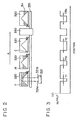
- Fig. 3 illustrates an example of electrical signal detected when the carriage on which a recording head and a plurality of ink cartridges are mounted together is moved against a detector 321.
- the carriage moves against the detector at a constant speed.
- the detected signal Vout is at a low level Ov only for a time TV. Since this signal is detected in synchronism with the movement of the carriage, it is possible to recognize that it is a signal for the tank for yellow ink. Then, a TM is detected for the magenta tank M. Similarly, thereafter, a TC for the cyan, and a TBk for the black are detected.
- the low level time for the detected signal has a length which corresponds to the remaining ink. In this way, not only the presence or absence of ink in each of the ink tanks can be detected, but also, the remaining ink can even be detected.
- the detection mechanism described in conjunction with Fig. 18 to Fig. 26 is capable of detecting the remaining ink in the ink tank of such a structure where a recording head and an ink tank are formed together, in addition to being capable of detecting the remaining ink in an ink cartridge. Further, it is possible for such a mechanism to detect the presence or absence of a recording head as well as a reading head arranged on a carriage.
- the main body of a recording apparatus with a sensor which is capable of detecting at least one of the carriage and recording head.
- the presence and absence of the recording head and the ink tank can be detected.
- a small motor can be employed for driving the carriage, thus making it possible to provide a small ink jet recording apparatus.
- the present invention produces an excellent effect on the recording head or the recording apparatus which is provided with means (such as electrothermal transducers, laser beam, or the like) for generating the thermal energy to be utilized as the energy, thereby the change of state of ink is created to discharge ink for recording, because with this method, it is possible to achieve a highly densified and precise recording.
- means such as electrothermal transducers, laser beam, or the like
- the principle is such that at least one driving signal, which provides a rapid temperature rise beyond a departure from nucleation boiling point in response to recording information, is applied to an electrothermal transducer disposed on a liquid (ink) retaining sheet or liquid passage whereby to cause the electrothermal transducer to generate thermal energy to produce film boiling on the thermoactive portion of the recording head; thus effectively leading to the resultant one to one formation of a bubble in the recording liquid (ink) for each of the driving signals.
- the liquid (ink) is discharged through a discharging port to produce at least one droplet.
- the driving signal is preferably in the form of pulses because the development and contraction of the bubbles can be effectuated instantaneously, thus discharging the liquid (ink) with particularly quick responses.
- the driving signal in the form of pulses is preferably such as disclosed in the specifications of U.S. Patent Nos. 4,463,359 and 4,345,262. In this respect, it is possible to execute an excellent recording in a better condition if the rate of the temperature increase of the heating surface is adopted as disclosed in the specification of U.S. Patent No. 4,313,124.
- the structure of the recording head may be as shown in each of the above-mentioned specifications wherein the structure is arranged to combine such discharge ports, liquid passages, and electrothermal transducers as disclosed in the specification (linear type liquid passage or right angle liquid passage).
- a structure such as disclosed in the specifications of U.S. Patent Nos. 4,558,333 and 4,459,600 wherein the portions thermally activated are arranged in a curved area.
- the present invention is effectively applicable to the structure disclosed in Japanese Laid-Open Application No. 59-123670 wherein a common slit is used as the discharging ports for plural electrothermal transducers, and to the structure disclosed in Japanese Patent Laid-Open Application No. 59-138461 wherein an aperture for absorbing pressure wave of the thermal energy is formed corresponding to the discharging ports.
- recording can be executed reliably and efficiently irrespective of the modes of the recording head.
- a full-line type recording head having a length corresponding to the maximum width of a medium which can be recorded by a recording apparatus.
- This full-line type head may be the one structured by combining a plurality of the recording heads disclosed in the above-mentioned specifications or a single full-line recording head which is integrally formed.
- the present invention is effectively applicable to a replaceable chip type recording head which is electrically connected with the main body of the apparatus, and to which the ink is supplied when it is mounted in the main assembly; or to a cartridge type recording head having an ink tank integrally provided for the head itself.
- Such constituents are capping means for the recording head, cleaning means, compression or suction means, preliminary heating means such as electrothermal transducers or heating elements other than such transducers or the combination of those types of elements, and the preliminary discharge mode which is adopted aside from the regular discharging for recording.
- the recording mode of the apparatus for example, the present invention is extremely effective in applying it not only to a recording mode in which only main color such as black or the like is used, but also to an apparatus having at least one of a multi-color mode with ink of different colors, or a full-color mode using the mixture of the colors, irrespective of whether the recording heads are integrally structured or it is structured by a combination of plural recording heads.
- the ink may be an ink material which is solidified below the room temperature but liquefied at the room temperature. Since the ink is controlled within the temperature not lower than 30°C and not higher than 70°C in order to stabilize its viscosity for the provision of the stable discharge in general, the ink may be such that it can be liquefied when the applicable recording signals are given.
- an ink having a nature of being liquefied only by the application of thermal energy such as an ink capable of being discharged as ink liquid by enabling itself to be liquefied anyway when the thermal energy is given in accordance with recording signals, and an ink which will have already begun solidifying itself by the time it reaches a recording medium.
- the ink in the form of liquid or solid in the recesses or through holes of a porous sheet such as disclosed in Japanese Patent Laid-Open Application No. 54-56847 or 60-71260 in order to enable the ink to face the electrothermal transducers.
- the most effective method applicable to the various kinds of ink described above is the method in which the aforesaid film boiling can be implemented.
- the mode of the recording apparatus it may be possible to adopt a copying apparatus combined with a reader in addition to the image output terminal which is integrally or independently provided for a word processor, computer, or other information processing apparatus. Also, it may be possible to adopt among others a mode of a facsimile apparatus having transmission and reception functions.
Landscapes
- Ink Jet (AREA)
- Particle Formation And Scattering Control In Inkjet Printers (AREA)
- Photographic Developing Apparatuses (AREA)
Claims (11)
- Réservoir d'encre destiné à être utilisé dans un appareil d'enregistrement à jet d'encre contenant une encre devant être amenée depuis ledit réservoir d'encre, caractérisé en ce qu'il comporte un prisme (321c) de réflexion de la lumière destiné à détecter la présence ou l'absence d'encre dans le réservoir d'encre, ledit prisme (321c) étant disposé sur une surface intérieure du réservoir d'encre où une partie d'alimentation (336) est prévue pour l'alimentation en encre, et comportant une partie déformée formée par des parties inclinées (341, 342) pour réfléchir de la lumière émise depuis l'extérieur du réservoir d'encre.
- Réservoir d'encre selon la revendication 1, dans lequel au moins la portion desdites parties inclinées (341, 342) où les parties restantes de l'encre sont détectées est formée d'une matière ayant une transparence à la lumière du même indice de réfraction que celui de l'encre contenue dans le réservoir d'encre ou un indice qui en est extrêmement proche, afin de détecter la position spécifique du niveau d'encre dans le réservoir d'encre.
- Réservoir d'encre selon la revendication 2, dans lequel ladite matière est du polypropylène.
- Réservoir d'encre selon l'une quelconque des revendications 1 à 3, dans lequel ledit prisme (321c) est formé d'une seule pièce avec le réservoir d'encre (320).
- Réservoir d'encre selon la revendication 1, dans lequel la surface pourvue de ladite partie d'alimentation est une surface plus basse dans une direction verticale, dans un état où le réservoir d'encre devant être utilisé est monté sur l'appareil d'enregistrement à jet d'encre.
- Appareil d'enregistrement à jet d'encre, caractérisé en ce qu'il porte au moins un réservoir d'encre (320) selon l'une quelconque des revendications 1 à 5 pour réaliser un enregistrement en utilisant de l'encre amenée depuis le réservoir d'encre, ledit appareil d'enregistrement à jet d'encre comportant en outre un moyen de détection (321) ayant une partie (321a) d'émission de lumière destinée à émettre de la lumière à travers ladite surface du réservoir d'encre où ledit prisme (321c) de réflexion de la lumière est disposé et une partie (321b) de réception de lumière destinée à recevoir de la lumière réfléchie par le prisme, dans lequel ladite partie d'émission de lumière est agencée sur le côté du réservoir d'encre où est disposée la partiel de réception de lumière.
- Appareil d'enregistrement à jet d'encre selon la revendication 6, comportant un moyen de balayage (351) destiné à déplacer ledit réservoir d'encre (320) dans une direction donnée en même temps qu'une tête d'enregistrement (350), ladite tête d'enregistrement (350) et ledit réservoir d'encre (320) étant montés de façon amovible sur ledit moyen de balayage, et ledit moyen de détection (321) étant positionné dans la plage sur laquelle ledit moyen de balayage se déplace.
- Appareil d'enregistrement à jet d'encre selon la revendication 7, dans lequel la lumière réfléchie entre les parties inclinées (341, 342) dudit prisme (321c) est réfléchie sensiblement dans la même direction (A) que celle dans laquelle le réservoir d'encre (320) est déplacé par le moyen de balayage (351).
- Appareil d'enregistrement à jet d'encre selon la revendication 7 ou 8, comportant un dispositif de commande (234) destiné à déterminer si au moins l'un de ladite tête d'enregistrement (350) et dudit réservoir d'encre (320) est installé ou non en recevant depuis ledit moyen de détection (321) le signal détecté qui est synchronisé avec le mouvement dudit moyen de balayage (351).
- Appareil d'enregistrement à jet d'encre selon l'une quelconque des revendications 7 à 9, dans lequel ladite tête d'enregistrement (350) est pourvue de transducteurs électrothermiques destinés, à générer de l'énergie thermique pour décharger de l'encre.
- Appareil d'enregistrement à jet d'encre selon l'une quelconque des revendications 7 à 10, dans lequel ladite tête d'enregistrement (350) décharge l'encre depuis les orifices de décharge en utilisant une ébullition pelliculaire devant être générée dans l'encre par l'énergie thermique qui est appliquée par lesdits transducteurs électrothermiques.
Applications Claiming Priority (7)
| Application Number | Priority Date | Filing Date | Title |
|---|---|---|---|
| JP12423893 | 1993-05-26 | ||
| JP12423893 | 1993-05-26 | ||
| JP16900393 | 1993-07-08 | ||
| JP16900393 | 1993-07-08 | ||
| JP23347493 | 1993-09-20 | ||
| JP23347493 | 1993-09-20 | ||
| EP94108032A EP0626267B1 (fr) | 1993-05-26 | 1994-05-25 | Appareil d'enregistrement par jet d'encre |
Related Parent Applications (2)
| Application Number | Title | Priority Date | Filing Date |
|---|---|---|---|
| EP94108032A Division EP0626267B1 (fr) | 1993-05-26 | 1994-05-25 | Appareil d'enregistrement par jet d'encre |
| EP94108032.7 Division | 1994-05-25 |
Publications (3)
| Publication Number | Publication Date |
|---|---|
| EP0955169A2 EP0955169A2 (fr) | 1999-11-10 |
| EP0955169A3 EP0955169A3 (fr) | 2000-03-01 |
| EP0955169B1 true EP0955169B1 (fr) | 2005-03-16 |
Family
ID=27314889
Family Applications (2)
| Application Number | Title | Priority Date | Filing Date |
|---|---|---|---|
| EP99115582A Revoked EP0955169B1 (fr) | 1993-05-26 | 1994-05-25 | Appareil d'enregistrement à jet d'encre |
| EP94108032A Expired - Lifetime EP0626267B1 (fr) | 1993-05-26 | 1994-05-25 | Appareil d'enregistrement par jet d'encre |
Family Applications After (1)
| Application Number | Title | Priority Date | Filing Date |
|---|---|---|---|
| EP94108032A Expired - Lifetime EP0626267B1 (fr) | 1993-05-26 | 1994-05-25 | Appareil d'enregistrement par jet d'encre |
Country Status (5)
| Country | Link |
|---|---|
| US (1) | US6137503A (fr) |
| EP (2) | EP0955169B1 (fr) |
| AT (2) | ATE191886T1 (fr) |
| DE (2) | DE69423999T2 (fr) |
| ES (2) | ES2236996T3 (fr) |
Cited By (1)
| Publication number | Priority date | Publication date | Assignee | Title |
|---|---|---|---|---|
| DE102009041650A1 (de) * | 2009-09-17 | 2011-03-24 | Pelikan Hardcopy Production Ag | Tintenpatrone mit Elementen für Füllstandsdetektion |
Families Citing this family (46)
| Publication number | Priority date | Publication date | Assignee | Title |
|---|---|---|---|---|
| JP2002292890A (ja) * | 2001-03-30 | 2002-10-09 | Brother Ind Ltd | インクカートリッジ |
| JP3359205B2 (ja) * | 1994-11-25 | 2002-12-24 | キヤノン株式会社 | 記録装置 |
| JPH0929989A (ja) * | 1995-07-14 | 1997-02-04 | Canon Inc | インク有無検出装置、インクタンク、キット、記録ユニット、記録装置、および情報処理システム |
| EP0956957B1 (fr) * | 1996-07-12 | 2004-11-10 | Canon Finetech Inc. | Appareil de formation d'image de type scanning |
| EP0844094B1 (fr) * | 1996-11-22 | 2004-06-09 | Seiko Epson Corporation | Appareil d'enregistrement à jet d'encre |
| JPH10323993A (ja) * | 1997-02-19 | 1998-12-08 | Canon Inc | 検出システム、該検出システムを用いる液体吐出記録装置と液体収納容器、及び、光量変化受光システム |
| KR19990032797A (ko) * | 1997-10-21 | 1999-05-15 | 윤종용 | 잉크 카트리지의 장착여부 판별장치 및 방법 |
| US6454400B1 (en) | 1998-09-01 | 2002-09-24 | Canon Kabushiki Kaisha | Liquid container, cartridge including liquid container, printing apparatus using cartridge and liquid discharge printing apparatus |
| JP4686843B2 (ja) | 1999-12-06 | 2011-05-25 | セイコーエプソン株式会社 | 記録装置用の検出装置、及び、これを備えた記録装置 |
| JP2002137414A (ja) | 2000-10-31 | 2002-05-14 | Canon Inc | インクジェット記録装置、およびインク残量検出方法 |
| EP1211081B1 (fr) | 2000-12-01 | 2006-05-31 | Seiko Epson Corporation | Système, dispositif et procédé pour délivrer des reçus et pour fournir des informations publicitaires |
| JP2002273911A (ja) * | 2001-03-15 | 2002-09-25 | Seiko Epson Corp | インクジェットプリンタ |
| US7237884B2 (en) | 2001-03-30 | 2007-07-03 | Brother Kogyo Kabushiki Kaisha | Ink cartridge |
| US7178911B2 (en) | 2001-03-30 | 2007-02-20 | Brother Kogyo Kabushiki Kaisha | Ink cartridge |
| US6619776B2 (en) * | 2001-03-30 | 2003-09-16 | Brother Kogyo Kabushiki Kaisha | Image forming device capable of detecting existence of ink and ink cartridge with high accuracy |
| CA2379725C (fr) | 2001-04-03 | 2007-06-12 | Seiko Epson Corporation | Cartouche a encre |
| US6485124B1 (en) | 2001-07-02 | 2002-11-26 | Lexmark International, Inc. | Optical alignment method and detector |
| US6631971B2 (en) * | 2001-07-18 | 2003-10-14 | Lexmark International, Inc. | Inkjet printer and method for use thereof |
| EP1354709B1 (fr) | 2002-04-16 | 2006-06-28 | Seiko Epson Corporation | Détecteur de cartouche d'encre, imprimante à jet d'encre avec celui-ci et cartouche d'encre détectée par celui-ci |
| TWI259149B (en) * | 2002-09-30 | 2006-08-01 | Canon Kk | Ink container and recording apparatus |
| US7725209B2 (en) | 2002-11-12 | 2010-05-25 | Objet Geometries Ltd | Three-dimensional object printing |
| ATE381992T1 (de) * | 2002-11-26 | 2008-01-15 | Seiko Epson Corp | Tintenpatrone |
| JP3624950B2 (ja) * | 2002-11-26 | 2005-03-02 | セイコーエプソン株式会社 | インクカートリッジ |
| US7040728B2 (en) * | 2003-06-06 | 2006-05-09 | Fuji Xerox Co., Ltd. | Geometry for a dual level fluid quantity sensing refillable fluid container |
| JP2005041183A (ja) * | 2003-07-25 | 2005-02-17 | Canon Inc | 液体収容容器 |
| JP2005053110A (ja) * | 2003-08-05 | 2005-03-03 | Canon Inc | インクタンク、記録装置、およびインク使用量監視システム |
| US7029083B2 (en) * | 2003-11-26 | 2006-04-18 | Fuji Xerox Co., Ltd. | Systems and methods for controllably refilling a fluid quantity sensing fluid ejection head |
| JP4576871B2 (ja) * | 2004-04-21 | 2010-11-10 | セイコーエプソン株式会社 | 収容物検出装置、容器、及びインクジェットプリンタ |
| JP2005343037A (ja) * | 2004-06-03 | 2005-12-15 | Canon Inc | インクジェット記録用のインク残量検出モジュール、該インク残量検出モジュールを備えたインクタンク、およびインクジェット記録装置 |
| JP2005343036A (ja) * | 2004-06-03 | 2005-12-15 | Canon Inc | インクジェット記録用のインク残量検出モジュール、該インク残量検出モジュールを備えたインクタンク、およびインクジェット記録装置 |
| JP2006272297A (ja) * | 2005-03-30 | 2006-10-12 | Seiko Epson Corp | 液滴吐出装置 |
| JP4400507B2 (ja) * | 2005-04-28 | 2010-01-20 | ブラザー工業株式会社 | 液滴噴射装置 |
| JP4590317B2 (ja) * | 2005-07-04 | 2010-12-01 | キヤノン株式会社 | 記録装置 |
| US7284848B2 (en) | 2005-11-28 | 2007-10-23 | Brother Kogyo Kabushiki Kaisha | Ink cartridges |
| JP4277850B2 (ja) * | 2005-11-30 | 2009-06-10 | ブラザー工業株式会社 | リフィルユニット |
| ATE538937T1 (de) | 2006-09-29 | 2012-01-15 | Brother Ind Ltd | Flüssigkeitskartusche und aufzeichnungssystem |
| ES2370294T3 (es) † | 2008-02-28 | 2011-12-14 | Brother Kogyo Kabushiki Kaisha | Cartucho de tinta, conjunto de cartuchos de tinta y sistema de determinación de cartucho de tinta. |
| JP2010228374A (ja) * | 2009-03-27 | 2010-10-14 | Brother Ind Ltd | インク供給装置 |
| JP2010228388A (ja) * | 2009-03-27 | 2010-10-14 | Brother Ind Ltd | 画像記録装置 |
| DE202010000938U1 (de) | 2010-01-22 | 2010-06-02 | Artech Gmbh Design + Production In Plastic | Tintenkartusche |
| JP5499989B2 (ja) | 2010-03-12 | 2014-05-21 | 株式会社リコー | 画像形成装置 |
| KR101532639B1 (ko) * | 2010-08-18 | 2015-06-30 | 가부시키가이샤 리코 | 화상 형성 장치 |
| JP6040526B2 (ja) * | 2011-06-03 | 2016-12-07 | 株式会社リコー | 画像形成装置 |
| JP5919652B2 (ja) * | 2011-06-03 | 2016-05-18 | 株式会社リコー | 画像形成装置 |
| JP5884305B2 (ja) * | 2011-06-13 | 2016-03-15 | セイコーエプソン株式会社 | 液体容器、および液体検出システム |
| DE202012003737U1 (de) | 2012-03-23 | 2012-04-25 | Pelikan Hardcopy Production Ag | Fluidaufnahmebehälter, insbesondere Tintenpatrone, für Tintenstrahldrucker |
Citations (3)
| Publication number | Priority date | Publication date | Assignee | Title |
|---|---|---|---|---|
| US4788444A (en) * | 1985-12-18 | 1988-11-29 | Lucas Electrical Electronics And Systems Limited | Liquid level detection |
| EP0486309A2 (fr) * | 1990-11-15 | 1992-05-20 | Canon Kabushiki Kaisha | Appareil d'enregistrement à jet d'encre |
| EP0573274A2 (fr) * | 1992-06-03 | 1993-12-08 | Canon Kabushiki Kaisha | Dispositif de détection de la quantité d'encre et appareil d'enregistrement muni d'un tel dispositif |
Family Cites Families (36)
| Publication number | Priority date | Publication date | Assignee | Title |
|---|---|---|---|---|
| CA1127227A (fr) | 1977-10-03 | 1982-07-06 | Ichiro Endo | Procede d'enregistrement a jet liquide et appareil d'enregistrement |
| JPS5936879B2 (ja) | 1977-10-14 | 1984-09-06 | キヤノン株式会社 | 熱転写記録用媒体 |
| US4330787A (en) | 1978-10-31 | 1982-05-18 | Canon Kabushiki Kaisha | Liquid jet recording device |
| US4345262A (en) | 1979-02-19 | 1982-08-17 | Canon Kabushiki Kaisha | Ink jet recording method |
| US4463359A (en) | 1979-04-02 | 1984-07-31 | Canon Kabushiki Kaisha | Droplet generating method and apparatus thereof |
| US4246489A (en) * | 1979-04-16 | 1981-01-20 | Tokyo Shibaura Electric Co., Ltd. | Liquid level detector for detecting a liquid level when reaching a prescribed height |
| US4313124A (en) | 1979-05-18 | 1982-01-26 | Canon Kabushiki Kaisha | Liquid jet recording process and liquid jet recording head |
| FR2492974A1 (fr) * | 1980-10-24 | 1982-04-30 | Geditec | Capteur optique de niveau |
| US4558333A (en) | 1981-07-09 | 1985-12-10 | Canon Kabushiki Kaisha | Liquid jet recording head |
| JPS59123670A (ja) | 1982-12-28 | 1984-07-17 | Canon Inc | インクジエツトヘツド |
| JPS59138461A (ja) | 1983-01-28 | 1984-08-08 | Canon Inc | 液体噴射記録装置 |
| JPS6071260A (ja) | 1983-09-28 | 1985-04-23 | Erumu:Kk | 記録装置 |
| JPS60172546A (ja) * | 1984-02-20 | 1985-09-06 | Konishiroku Photo Ind Co Ltd | インク残量検出装置 |
| US4551734A (en) * | 1984-12-06 | 1985-11-05 | Tektronix, Inc. | Ink cartridge with ink level sensor |
| JPS61249761A (ja) * | 1985-04-27 | 1986-11-06 | Tokyo Juki Ind Co Ltd | 液体残量検知装置 |
| JPH0696328B2 (ja) | 1985-09-12 | 1994-11-30 | キヤノン株式会社 | プリント装置 |
| JPH0698769B2 (ja) * | 1985-11-15 | 1994-12-07 | キヤノン株式会社 | 記録装置 |
| JPS62152963A (ja) * | 1985-12-26 | 1987-07-07 | 富士重工業株式会社 | 鉄道用コンクリ−トミキサ−車 |
| JPS62156963A (ja) * | 1985-12-28 | 1987-07-11 | Canon Inc | 記録装置 |
| JPS62246740A (ja) * | 1986-04-18 | 1987-10-27 | Canon Inc | インクジエツト記録装置 |
| JPS63147650A (ja) * | 1986-12-12 | 1988-06-20 | Canon Inc | 記録装置 |
| US4709245A (en) * | 1986-12-22 | 1987-11-24 | Eastman Kodak Company | Ink jet printer for cooperatively printing with a plurality of insertable print/cartridges |
| JP2525803B2 (ja) * | 1987-04-09 | 1996-08-21 | キヤノン株式会社 | インクジェットプリント装置 |
| US4998022A (en) * | 1988-03-22 | 1991-03-05 | Conax Buffalo Corporation | Optical liquid level sensor using a polytetrafluoroethylene perfluoroalkoxy material |
| JPH02102061A (ja) * | 1988-10-11 | 1990-04-13 | Seiko Epson Corp | インク残量検出装置 |
| EP0374762B1 (fr) * | 1988-12-16 | 1995-03-15 | Canon Kabushiki Kaisha | Appareil d'enregistrement avec tête d'enregistrement amovible |
| JPH041056A (ja) * | 1990-04-19 | 1992-01-06 | Canon Inc | インクジェット記録装置 |
| US5168291A (en) * | 1989-04-24 | 1992-12-01 | Canon Kabushiki Kaisha | Recording apparatus and ink cassette therefor |
| CA2025561C (fr) * | 1989-09-18 | 1995-07-11 | Seiichiro Karita | Tete d'enregistrement a capuchon |
| US5291224A (en) * | 1989-10-27 | 1994-03-01 | Canon Kabushiki Kaisha | Sheet feeding apparatus using pairs of spur rollers |
| US5070346A (en) * | 1990-01-30 | 1991-12-03 | Seiko Epson Corporation | Ink near-end detecting device |
| JPH058383A (ja) * | 1991-07-02 | 1993-01-19 | Canon Inc | インクジエツト記録装置 |
| JP3078880B2 (ja) * | 1991-07-29 | 2000-08-21 | アルプス電気株式会社 | インクジェットプリンタのインク残量検出方法 |
| EP0860285B1 (fr) * | 1991-12-11 | 2002-03-06 | Canon Kabushiki Kaisha | Cartouche à jet d'encre |
| JP3180401B2 (ja) * | 1991-12-24 | 2001-06-25 | セイコーエプソン株式会社 | インクジェットプリンタにおけるインク吐出回復装置 |
| JPH0647985A (ja) * | 1992-07-30 | 1994-02-22 | Canon Inc | インクジェット記録装置および該装置にて行われるインクジェットヘッドの装着状態の判定方法 |
-
1994
- 1994-05-25 AT AT94108032T patent/ATE191886T1/de active
- 1994-05-25 EP EP99115582A patent/EP0955169B1/fr not_active Revoked
- 1994-05-25 ES ES99115582T patent/ES2236996T3/es not_active Expired - Lifetime
- 1994-05-25 DE DE69423999T patent/DE69423999T2/de not_active Expired - Lifetime
- 1994-05-25 AT AT99115582T patent/ATE290954T1/de not_active IP Right Cessation
- 1994-05-25 EP EP94108032A patent/EP0626267B1/fr not_active Expired - Lifetime
- 1994-05-25 ES ES94108032T patent/ES2145074T3/es not_active Expired - Lifetime
- 1994-05-25 DE DE69434305T patent/DE69434305T2/de not_active Expired - Lifetime
-
1997
- 1997-05-13 US US08/855,282 patent/US6137503A/en not_active Expired - Fee Related
Patent Citations (3)
| Publication number | Priority date | Publication date | Assignee | Title |
|---|---|---|---|---|
| US4788444A (en) * | 1985-12-18 | 1988-11-29 | Lucas Electrical Electronics And Systems Limited | Liquid level detection |
| EP0486309A2 (fr) * | 1990-11-15 | 1992-05-20 | Canon Kabushiki Kaisha | Appareil d'enregistrement à jet d'encre |
| EP0573274A2 (fr) * | 1992-06-03 | 1993-12-08 | Canon Kabushiki Kaisha | Dispositif de détection de la quantité d'encre et appareil d'enregistrement muni d'un tel dispositif |
Cited By (1)
| Publication number | Priority date | Publication date | Assignee | Title |
|---|---|---|---|---|
| DE102009041650A1 (de) * | 2009-09-17 | 2011-03-24 | Pelikan Hardcopy Production Ag | Tintenpatrone mit Elementen für Füllstandsdetektion |
Also Published As
| Publication number | Publication date |
|---|---|
| EP0626267A2 (fr) | 1994-11-30 |
| ES2236996T3 (es) | 2005-07-16 |
| EP0626267A3 (fr) | 1995-07-05 |
| DE69423999T2 (de) | 2000-11-02 |
| ES2145074T3 (es) | 2000-07-01 |
| ATE290954T1 (de) | 2005-04-15 |
| EP0955169A2 (fr) | 1999-11-10 |
| EP0955169A3 (fr) | 2000-03-01 |
| EP0626267B1 (fr) | 2000-04-19 |
| DE69434305T2 (de) | 2006-04-13 |
| DE69423999D1 (de) | 2000-05-25 |
| US6137503A (en) | 2000-10-24 |
| ATE191886T1 (de) | 2000-05-15 |
| DE69434305D1 (de) | 2005-04-21 |
Similar Documents
| Publication | Publication Date | Title |
|---|---|---|
| EP0626267B1 (fr) | Appareil d'enregistrement par jet d'encre | |
| US6024428A (en) | Recording apparatus having a device for detecting the presence or absence of a liquid | |
| US6729711B1 (en) | Ink jet recording apparatus | |
| EP0881080B1 (fr) | Dispositif de détection de la quantité d'encre et appareil d'enregistrement muni d'un tel dispositif | |
| US6234603B1 (en) | Sensing system for detecting presence of an ink container and level of ink therein | |
| US6443546B1 (en) | Printing apparatus and control method that includes an optical detector for detecting the presence or absence of an ink tank and ink therein | |
| MXPA96005882A (en) | Detection system to detect the presence of an ink container and its level of it | |
| EP0857574B1 (fr) | Imprimante et télécopieur l'utilisant | |
| US6296354B1 (en) | Ink container with plural ink chambers emptied sequentially, and recording apparatus having the same | |
| JP3397441B2 (ja) | インクジェット記録装置 | |
| EP0749842A2 (fr) | Dispositif d'enregistrement à jet d'encre avec détection de disfonctionnement de la décharge | |
| JPH10230616A (ja) | 容器情報検知装置およびインクジェットプリント装置 | |
| JP3210190B2 (ja) | インクジェット記録装置 | |
| KR19980075805A (ko) | 잉크 용기의 존재와 그 내부의 잉크의 레벨을 검출하기 위한 센싱 시스템 | |
| EP0752316B1 (fr) | Agencement de détection de la décharge de l'encre pour un appareil d'enregistrement par jet d'encre | |
| JP3501663B2 (ja) | 液体収納容器、及び、その液体収納容器を含むカートリッジ、及び、そのカートリッジを用いる記録装置、及び、液体吐出記録装置 | |
| JP2000043282A (ja) | 液体収納容器、及び、その液体収納容器を含むカートリッジ、及び、そのカートリッジを用いる記録装置 | |
| JPH08323991A (ja) | 記録装置 | |
| JP3264592B2 (ja) | インクジェット記録装置 | |
| JPH09240008A (ja) | 記録装置及びその装置を用いたファクシミリ装置 | |
| JPH07329315A (ja) | 液量検知方法、該方法を適用した記録装置および情報処理システム | |
| JPH09240009A (ja) | 記録装置及びその装置を用いたファクシミリ装置 | |
| JPH06171112A (ja) | インクジェット記録装置 | |
| HK1009673B (en) | Printer and facsimile apparatus using printer | |
| HK1014688B (en) | Ink discharge detection arrangement for an inkjet recording apparatus |
Legal Events
| Date | Code | Title | Description |
|---|---|---|---|
| PUAI | Public reference made under article 153(3) epc to a published international application that has entered the european phase |
Free format text: ORIGINAL CODE: 0009012 |
|
| AC | Divisional application: reference to earlier application |
Ref document number: 626267 Country of ref document: EP |
|
| AK | Designated contracting states |
Kind code of ref document: A2 Designated state(s): AT BE CH DE DK ES FR GB GR IE IT LI LU MC NL PT SE |
|
| AX | Request for extension of the european patent |
Free format text: SI |
|
| PUAL | Search report despatched |
Free format text: ORIGINAL CODE: 0009013 |
|
| AK | Designated contracting states |
Kind code of ref document: A3 Designated state(s): AT BE CH DE DK ES FR GB GR IE IT LI LU MC NL PT SE |
|
| AX | Request for extension of the european patent |
Free format text: SI |
|
| 17P | Request for examination filed |
Effective date: 20000713 |
|
| AKX | Designation fees paid |
Free format text: AT BE CH DE DK ES FR GB GR IE IT LI LU MC NL PT SE |
|
| 17Q | First examination report despatched |
Effective date: 20010329 |
|
| GRAP | Despatch of communication of intention to grant a patent |
Free format text: ORIGINAL CODE: EPIDOSNIGR1 |
|
| GRAS | Grant fee paid |
Free format text: ORIGINAL CODE: EPIDOSNIGR3 |
|
| GRAA | (expected) grant |
Free format text: ORIGINAL CODE: 0009210 |
|
| AC | Divisional application: reference to earlier application |
Ref document number: 0626267 Country of ref document: EP Kind code of ref document: P |
|
| AK | Designated contracting states |
Kind code of ref document: B1 Designated state(s): AT BE CH DE DK ES FR GB GR IE IT LI LU MC NL PT SE |
|
| PG25 | Lapsed in a contracting state [announced via postgrant information from national office to epo] |
Ref country code: BE Free format text: LAPSE BECAUSE OF FAILURE TO SUBMIT A TRANSLATION OF THE DESCRIPTION OR TO PAY THE FEE WITHIN THE PRESCRIBED TIME-LIMIT Effective date: 20050316 Ref country code: AT Free format text: LAPSE BECAUSE OF FAILURE TO SUBMIT A TRANSLATION OF THE DESCRIPTION OR TO PAY THE FEE WITHIN THE PRESCRIBED TIME-LIMIT Effective date: 20050316 |
|
| REG | Reference to a national code |
Ref country code: GB Ref legal event code: FG4D |
|
| REG | Reference to a national code |
Ref country code: CH Ref legal event code: EP |
|
| REG | Reference to a national code |
Ref country code: IE Ref legal event code: FG4D |
|
| REF | Corresponds to: |
Ref document number: 69434305 Country of ref document: DE Date of ref document: 20050421 Kind code of ref document: P |
|
| REG | Reference to a national code |
Ref country code: CH Ref legal event code: NV Representative=s name: BOVARD AG PATENTANWAELTE |
|
| PG25 | Lapsed in a contracting state [announced via postgrant information from national office to epo] |
Ref country code: LU Free format text: LAPSE BECAUSE OF NON-PAYMENT OF DUE FEES Effective date: 20050525 Ref country code: IE Free format text: LAPSE BECAUSE OF NON-PAYMENT OF DUE FEES Effective date: 20050525 |
|
| PG25 | Lapsed in a contracting state [announced via postgrant information from national office to epo] |
Ref country code: GR Free format text: LAPSE BECAUSE OF FAILURE TO SUBMIT A TRANSLATION OF THE DESCRIPTION OR TO PAY THE FEE WITHIN THE PRESCRIBED TIME-LIMIT Effective date: 20050616 Ref country code: DK Free format text: LAPSE BECAUSE OF FAILURE TO SUBMIT A TRANSLATION OF THE DESCRIPTION OR TO PAY THE FEE WITHIN THE PRESCRIBED TIME-LIMIT Effective date: 20050616 |
|
| REG | Reference to a national code |
Ref country code: ES Ref legal event code: FG2A Ref document number: 2236996 Country of ref document: ES Kind code of ref document: T3 |
|
| PG25 | Lapsed in a contracting state [announced via postgrant information from national office to epo] |
Ref country code: PT Free format text: LAPSE BECAUSE OF FAILURE TO SUBMIT A TRANSLATION OF THE DESCRIPTION OR TO PAY THE FEE WITHIN THE PRESCRIBED TIME-LIMIT Effective date: 20050907 |
|
| PLBI | Opposition filed |
Free format text: ORIGINAL CODE: 0009260 |
|
| PLAZ | Examination of admissibility of opposition: despatch of communication + time limit |
Free format text: ORIGINAL CODE: EPIDOSNOPE2 |
|
| PLBA | Examination of admissibility of opposition: reply received |
Free format text: ORIGINAL CODE: EPIDOSNOPE4 |
|
| 26 | Opposition filed |
Opponent name: PELIKAN HARDCOPY(INTERNATIONAL) AG Effective date: 20051216 Opponent name: ARTECH GMBH Effective date: 20051215 |
|
| REG | Reference to a national code |
Ref country code: IE Ref legal event code: MM4A |
|
| ET | Fr: translation filed | ||
| PLBA | Examination of admissibility of opposition: reply received |
Free format text: ORIGINAL CODE: EPIDOSNOPE4 |
|
| PLAX | Notice of opposition and request to file observation + time limit sent |
Free format text: ORIGINAL CODE: EPIDOSNOBS2 |
|
| NLR1 | Nl: opposition has been filed with the epo |
Opponent name: PELIKAN HARDCOPY(INTERNATIONAL) AG Opponent name: ARTECH GMBH |
|
| PLBB | Reply of patent proprietor to notice(s) of opposition received |
Free format text: ORIGINAL CODE: EPIDOSNOBS3 |
|
| PLAB | Opposition data, opponent's data or that of the opponent's representative modified |
Free format text: ORIGINAL CODE: 0009299OPPO |
|
| PG25 | Lapsed in a contracting state [announced via postgrant information from national office to epo] |
Ref country code: MC Free format text: LAPSE BECAUSE OF NON-PAYMENT OF DUE FEES Effective date: 20050531 |
|
| R26 | Opposition filed (corrected) |
Opponent name: PELIKAN HARDCOPY(INTERNATIONAL) AG Effective date: 20051216 Opponent name: ARTECH GMBH Effective date: 20051215 |
|
| PLAY | Examination report in opposition despatched + time limit |
Free format text: ORIGINAL CODE: EPIDOSNORE2 |
|
| PG25 | Lapsed in a contracting state [announced via postgrant information from national office to epo] |
Ref country code: SE Free format text: LAPSE BECAUSE OF FAILURE TO SUBMIT A TRANSLATION OF THE DESCRIPTION OR TO PAY THE FEE WITHIN THE PRESCRIBED TIME-LIMIT Effective date: 20050616 |
|
| NLR1 | Nl: opposition has been filed with the epo |
Opponent name: PELIKAN HARDCOPY (INTERNATIONAL) AG Opponent name: ARTECH GMBH |
|
| PLAH | Information related to despatch of examination report in opposition + time limit modified |
Free format text: ORIGINAL CODE: EPIDOSCORE2 |
|
| PLAB | Opposition data, opponent's data or that of the opponent's representative modified |
Free format text: ORIGINAL CODE: 0009299OPPO |
|
| PLBC | Reply to examination report in opposition received |
Free format text: ORIGINAL CODE: EPIDOSNORE3 |
|
| R26 | Opposition filed (corrected) |
Opponent name: PELIKAN HARDCOPY(INTERNATIONAL) AG Effective date: 20051216 Opponent name: ARTECH GMBH Effective date: 20051215 |
|
| NLR1 | Nl: opposition has been filed with the epo |
Opponent name: PELIKAN HARDCOPY(INTERNATIONAL) AG Opponent name: ARTECH GMBH |
|
| APBM | Appeal reference recorded |
Free format text: ORIGINAL CODE: EPIDOSNREFNO |
|
| APBP | Date of receipt of notice of appeal recorded |
Free format text: ORIGINAL CODE: EPIDOSNNOA2O |
|
| APAH | Appeal reference modified |
Free format text: ORIGINAL CODE: EPIDOSCREFNO |
|
| APBM | Appeal reference recorded |
Free format text: ORIGINAL CODE: EPIDOSNREFNO |
|
| APBP | Date of receipt of notice of appeal recorded |
Free format text: ORIGINAL CODE: EPIDOSNNOA2O |
|
| APBM | Appeal reference recorded |
Free format text: ORIGINAL CODE: EPIDOSNREFNO |
|
| APBP | Date of receipt of notice of appeal recorded |
Free format text: ORIGINAL CODE: EPIDOSNNOA2O |
|
| APBQ | Date of receipt of statement of grounds of appeal recorded |
Free format text: ORIGINAL CODE: EPIDOSNNOA3O |
|
| APBQ | Date of receipt of statement of grounds of appeal recorded |
Free format text: ORIGINAL CODE: EPIDOSNNOA3O |
|
| REG | Reference to a national code |
Ref country code: CH Ref legal event code: PFA Owner name: CANON KABUSHIKI KAISHA Free format text: CANON KABUSHIKI KAISHA#30-2, 3-CHOME, SHIMOMARUKO, OHTA-KU#TOKYO (JP) -TRANSFER TO- CANON KABUSHIKI KAISHA#30-2, 3-CHOME, SHIMOMARUKO, OHTA-KU#TOKYO (JP) |
|
| PGFP | Annual fee paid to national office [announced via postgrant information from national office to epo] |
Ref country code: CH Payment date: 20120504 Year of fee payment: 19 Ref country code: NL Payment date: 20120516 Year of fee payment: 19 Ref country code: DE Payment date: 20120531 Year of fee payment: 19 |
|
| PGFP | Annual fee paid to national office [announced via postgrant information from national office to epo] |
Ref country code: FR Payment date: 20120620 Year of fee payment: 19 Ref country code: GB Payment date: 20120517 Year of fee payment: 19 |
|
| REG | Reference to a national code |
Ref country code: DE Ref legal event code: R103 Ref document number: 69434305 Country of ref document: DE Ref country code: DE Ref legal event code: R064 Ref document number: 69434305 Country of ref document: DE |
|
| PGFP | Annual fee paid to national office [announced via postgrant information from national office to epo] |
Ref country code: IT Payment date: 20120514 Year of fee payment: 19 |
|
| PLAB | Opposition data, opponent's data or that of the opponent's representative modified |
Free format text: ORIGINAL CODE: 0009299OPPO |
|
| R26 | Opposition filed (corrected) |
Opponent name: ARTECH GMBH Effective date: 20051215 Opponent name: PELIKAN HARDCOPY PRODUCTION AG Effective date: 20051216 |
|
| APBU | Appeal procedure closed |
Free format text: ORIGINAL CODE: EPIDOSNNOA9O |
|
| RDAF | Communication despatched that patent is revoked |
Free format text: ORIGINAL CODE: EPIDOSNREV1 |
|
| RDAG | Patent revoked |
Free format text: ORIGINAL CODE: 0009271 |
|
| STAA | Information on the status of an ep patent application or granted ep patent |
Free format text: STATUS: PATENT REVOKED |
|
| PGFP | Annual fee paid to national office [announced via postgrant information from national office to epo] |
Ref country code: ES Payment date: 20120503 Year of fee payment: 19 |
|
| REG | Reference to a national code |
Ref country code: CH Ref legal event code: PL |
|
| 27W | Patent revoked |
Effective date: 20120927 |
|
| GBPR | Gb: patent revoked under art. 102 of the ep convention designating the uk as contracting state |
Effective date: 20120927 |
|
| PG25 | Lapsed in a contracting state [announced via postgrant information from national office to epo] |
Ref country code: CH Free format text: LAPSE BECAUSE OF THE APPLICANT RENOUNCES Effective date: 20050316 Ref country code: LI Free format text: LAPSE BECAUSE OF THE APPLICANT RENOUNCES Effective date: 20050316 |
|
| REG | Reference to a national code |
Ref country code: DE Ref legal event code: R107 Ref document number: 69434305 Country of ref document: DE Effective date: 20130314 |