EP0955253A2 - Vorrichtung und Verfahren zum Transport von Gegenständen durch eine Folge von Bearbeitungsstationen - Google Patents
Vorrichtung und Verfahren zum Transport von Gegenständen durch eine Folge von Bearbeitungsstationen Download PDFInfo
- Publication number
- EP0955253A2 EP0955253A2 EP99303560A EP99303560A EP0955253A2 EP 0955253 A2 EP0955253 A2 EP 0955253A2 EP 99303560 A EP99303560 A EP 99303560A EP 99303560 A EP99303560 A EP 99303560A EP 0955253 A2 EP0955253 A2 EP 0955253A2
- Authority
- EP
- European Patent Office
- Prior art keywords
- carriage
- article
- support
- carrier
- lower support
- Prior art date
- Legal status (The legal status is an assumption and is not a legal conclusion. Google has not performed a legal analysis and makes no representation as to the accuracy of the status listed.)
- Withdrawn
Links
Images

Classifications
-
- B—PERFORMING OPERATIONS; TRANSPORTING
- B65—CONVEYING; PACKING; STORING; HANDLING THIN OR FILAMENTARY MATERIAL
- B65G—TRANSPORT OR STORAGE DEVICES, e.g. CONVEYORS FOR LOADING OR TIPPING, SHOP CONVEYOR SYSTEMS OR PNEUMATIC TUBE CONVEYORS
- B65G49/00—Conveying systems characterised by their application for specified purposes not otherwise provided for
- B65G49/02—Conveying systems characterised by their application for specified purposes not otherwise provided for for conveying workpieces through baths of liquid
- B65G49/04—Conveying systems characterised by their application for specified purposes not otherwise provided for for conveying workpieces through baths of liquid the workpieces being immersed and withdrawn by movement in a vertical direction
- B65G49/0409—Conveying systems characterised by their application for specified purposes not otherwise provided for for conveying workpieces through baths of liquid the workpieces being immersed and withdrawn by movement in a vertical direction specially adapted for workpieces of definite length
- B65G49/0413—Conveying systems characterised by their application for specified purposes not otherwise provided for for conveying workpieces through baths of liquid the workpieces being immersed and withdrawn by movement in a vertical direction specially adapted for workpieces of definite length arrangements for conveyance through the bath
- B65G49/0431—Conveying systems characterised by their application for specified purposes not otherwise provided for for conveying workpieces through baths of liquid the workpieces being immersed and withdrawn by movement in a vertical direction specially adapted for workpieces of definite length arrangements for conveyance through the bath reciprocating conveying means
-
- B—PERFORMING OPERATIONS; TRANSPORTING
- B65—CONVEYING; PACKING; STORING; HANDLING THIN OR FILAMENTARY MATERIAL
- B65G—TRANSPORT OR STORAGE DEVICES, e.g. CONVEYORS FOR LOADING OR TIPPING, SHOP CONVEYOR SYSTEMS OR PNEUMATIC TUBE CONVEYORS
- B65G25/00—Conveyors comprising a cyclically-moving, e.g. reciprocating, carrier or impeller which is disengaged from the load during the return part of its movement
- B65G25/02—Conveyors comprising a cyclically-moving, e.g. reciprocating, carrier or impeller which is disengaged from the load during the return part of its movement the carrier or impeller having different forward and return paths of movement, e.g. walking beam conveyors
-
- B—PERFORMING OPERATIONS; TRANSPORTING
- B65—CONVEYING; PACKING; STORING; HANDLING THIN OR FILAMENTARY MATERIAL
- B65G—TRANSPORT OR STORAGE DEVICES, e.g. CONVEYORS FOR LOADING OR TIPPING, SHOP CONVEYOR SYSTEMS OR PNEUMATIC TUBE CONVEYORS
- B65G49/00—Conveying systems characterised by their application for specified purposes not otherwise provided for
- B65G49/02—Conveying systems characterised by their application for specified purposes not otherwise provided for for conveying workpieces through baths of liquid
- B65G49/025—Conveying systems characterised by their application for specified purposes not otherwise provided for for conveying workpieces through baths of liquid conveyor feeding and discharging means
Definitions
- This invention relates to conveying apparatus and a conveying method.
- conveying apparatus comprising a carriage, guide means arranged to guide said carriage along a path such that a substantially vertical movement of said carriage is followed by a substantially horizontal movement of said carriage, and driving means arranged to advance said carriage along said path.
- a method comprising advancing a carriage along a path while guiding said carriage such that a substantially vertical movement of said carriage is followed by a substantially horizontal movement thereof.
- the driving means can take the form of a single motor.
- the motion of the carriage along the path is employed to transfer one or more articles through a plurality of processing stages or stations, which may take the form of processing tanks.
- the guide means preferably takes the form of a cam-and-follower arrangement, with the cam being endless and supported on the carriage or another support and the follower being supported on that other support or the carriage, to cause the path of movement of the carriage to be endless.
- the driving means may include a rotary arm radially slidably linked to the follower or the cam, as the case may be.
- a beam may extend over such stages and be mounted on the carriage so as to be substantially vertically movable relative thereto by a second driving means which could include a second motor or could be operated by such single motor of the first-mentioned driving means.
- a carrier comprising an upper support, a lower support supported by said upper support and for unloadably supporting at least one article to be treated, said upper support being displaceable relative to said lower support from a treatment position in which unloading of the article(s) from said lower support is hindered by said upper support to an unloading position in which said unloading is not hindered by said upper support.
- the lower support can be a horizontal bar with one or more clips for receiving the article(s) or can be a basket with or without such clip(s).
- a method comprising loading at least one article into a carrier with a support of said carrier being located beneath said article(s), bringing said support to above said article(s), treating said article(s), bringing said support to below said article(s), and unloading said article(s) from said carrier.
- a method comprising loading at least one article into a lower support of a carrier with said lower support of said carrier being located beneath said article(s) and an upper support of said carrier not hindering said loading, bringing said upper support to above said article(s), treating said article(s), bringing said upper support to a position in which it does not hinder unloading of said article(s), and unloading said article(s) from said lower support.
- loading and unloading of the article(s) can be performed in a substantially unhindered manner.
- a carrier comprising only one elongate support from which the article(s) is/are suspended in the treatment condition and for the support to be inverted for loading and unloading of the article(s).
- this arrangement can be disadvantageous, for example cleaning liquid can drip onto the article(s) from suspension members, e.g. clips, below the support in the treatment condition. Therefore, in such circumstances, the combination of an upper support and a lower support as mentioned above is preferable.
- the article(s) can take the form of one or more machined articles, for example optical lenses or pieces of jewellery.
- the treatment can take the form of, for example, cleaning or sterilizing.
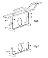
- Figure 7 is a view similar to Figure 5, but of a lower support constituting part of that other modified version.
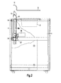
- the system comprises a cabinet 1 receiving along and in its top a row of steel tanks (of which one is seen and referenced 2) to which are fitted respective ultrasonic transducers (not shown) and which contain cleaning liquids (not shown) for ultrasonic liquid cleaning of optical lenses (not shown) carried in a plurality of baskets (not shown) suspended beneath respective stepping brackets (of which one is shown and referenced 3).
- Each bracket 3 is formed with a through hole 4 able fittingly to receive any one of a horizontal row of vertical pegs 5 arranged along the top of a sheet metal beam 6 extending parallelly to the row of tanks 2.
- the rear end zone of each bracket 3 is shaped to nest against the upper end zone of the beam.
- a traversing carriage 7 is mounted in respective upper and lower horizontal slides 8 fixed to the cabinet, so that the carriage is slidable along the cabinet.
- a lift carriage 9 is guided by vertical slides 10 fixed thereto co-operating with vertical guides 11 fixed to the carriage 7, so that the carriage 9 is vertically reciprocable relative to the carriage 7.
- respective vertical guides 12 are fixed to the carriage 7 outwardly of the respective guides 11 with which co-operate respective vertical slides 13A and 13B fixed to the beam 6.
- Fixed to the rear wall of the cabinet 1 is a slot-form cam 14 of substantially rectangular, in this case substantially square, form, with two vertical sides and two horizontal sides.
- the cam 14 co-operates with a roller follower 15 mounted on a pin 16 extending through a hole 17 through the carriage 7 and fixed to the carriage 9.
- An electric motor 18 mounted on the cabinet drives, via a belt 19, a pulley 20 the axis of rotation of which is fixed relative to the cabinet 1.
- the pulley 20 rotates an arm 21 in a clockwise direction in Figure 1.
- the arm 21 includes a pair of guides 22 in which slides a block 23.
- the block 23 is rotatably connected to the slide 9 by way of a rotary bearing 24.
- This arrangement allows the circular motion provided by the arm 21 to be constrained to the substantially square motion produced by the cam-and-follower arrangement 14,15.
- Mounted on the slide 13A at its lower end zone so as to be turnable about a horizontal pivot pin 25' is a spring-loaded latch 25 which is urged by its spring (not shown) to turn clockwise into the position illustrated in Figure 1.
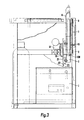
- a second electric motor 26 drives a crank 27 to reciprocate vertically a sliding block 28 guided in vertical guides fixed relative to the cabinet 1.
- the motor 18 is de-energised to stop the motion of the carriage 7 and the motor 26 is energised to cause the block 28, via the latch 25, to lift the beam 6 so that the pegs 5 engage in the holes 4 in respective brackets 3 and the motor 26 performs a predetermined number of revolutions to cause the baskets carried by the brackets 3 to reciprocate vertically in the respective tanks 2 and thereby to perform a washing action upon the optical lenses in the baskets.
- the beam 6 is lifted and lowered between the positions shown in dot-dash lines and full lines in Figures 2 and 3.
- the motor 18 is re-energised to advance the roller follower 15 up the vertical side of the cam 14 to cause the carriage 9 to engage beneath the top of the beam 6 and lift the beam to a level to bring the baskets upwards out of the tanks 2.
- the roller follower 15 continues along the upper horizontal side of the cam 14 and so advance the beam 6 and thus the brackets 3 and the baskets to the right in Figure 1 until the roller follower 15 turns the corner into the right-hand vertical side of the cam 14.
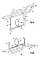
- the modified version of the carrier has an upper support 30 including a stepping bracket 3 formed with a through hole 4.
- the rear end zone 3a of the bracket 3 is cranked to nest against the upper end zone of the beam 6 described with reference to Figures 1 to 3.
- a handle 31 fixed to a middle zone of the bracket 3 projects upwardly to substantially the same extent as the cranked zone 3a.
- the bracket 3 is in the form of a channel of U-section.
- Two legs 32 extend downwards from the middle zone of the bracket 3 and have pivotally suspended therefrom a U-shape lower support 33 so that the supports 30 and 33 are turnable through at least 180° relative to each other about horizontal pivots 34 providing a horizontal axis of turning.
- the base of the U-shape lower support 33 is a horizontal bar 35 on which are mounted upwardly extending resilient clips (of which one is shown and referenced 36) which are arranged in a horizontal row along the bar and which have respective lenses 37 inserted downwardly into them.
- the upper support 30 extends above the lenses 37 in the clips 36.
- the upper support 30 can be swung down through 180° relative to the lower support 33, into the condition shown in Figure 5, in which the carrier 30,33 can be placed on a horizontal surface, if desired, and the lenses 37 loaded or unloaded unhindered by the support 30.
- the carrier version shown in Figures 6 and 7 differs from that shown in Figures 4 and 5 in that the lower support 33 is readily detachably mounted on the upper support 30 and that the lower support 33 is so designed as to be stably free-standing when detached.
- the lower ends of the vertical limbs 38 of the upper support 30 are formed with L-shaped slots 39 to form hooks 40 to receive detachably the respective pivots 34.
- the vertical limbs 41 of the lower support 33 are of T-shape, so that, by way of the cross-bars of the Ts, the lower support can rest stably on a horizontal surface when detached.
- This version has the advantage that the user need not have one support 30 for each support 33, which, for efficient use of the whole apparatus, can involve having considerably more supports 30 than necessarily present on the beam 6, but the user can have more supports 33 than supports 30 and thus prepare rows of lenses 37 in the supports 33 well before they are required to be treated.
Landscapes
- Engineering & Computer Science (AREA)
- Mechanical Engineering (AREA)
- Specific Conveyance Elements (AREA)
- Apparatus For Disinfection Or Sterilisation (AREA)
Applications Claiming Priority (4)
| Application Number | Priority Date | Filing Date | Title |
|---|---|---|---|
| GB9809579 | 1998-05-06 | ||
| GBGB9809579.7A GB9809579D0 (en) | 1998-05-06 | 1998-05-06 | Apparatus and method |
| GBGB9815240.8A GB9815240D0 (en) | 1998-05-06 | 1998-07-15 | Apparatus and method |
| GB9815240 | 1998-07-15 |
Publications (2)
| Publication Number | Publication Date |
|---|---|
| EP0955253A2 true EP0955253A2 (de) | 1999-11-10 |
| EP0955253A3 EP0955253A3 (de) | 2000-04-12 |
Family
ID=26313595
Family Applications (1)
| Application Number | Title | Priority Date | Filing Date |
|---|---|---|---|
| EP99303560A Withdrawn EP0955253A3 (de) | 1998-05-06 | 1999-05-06 | Vorrichtung und Verfahren zum Transport von Gegenständen durch eine Folge von Bearbeitungsstationen |
Country Status (1)
| Country | Link |
|---|---|
| EP (1) | EP0955253A3 (de) |
Cited By (2)
| Publication number | Priority date | Publication date | Assignee | Title |
|---|---|---|---|---|
| WO2006079494A3 (de) * | 2005-01-27 | 2007-02-15 | Carl Zeiss Vision Gmbh | Haltevorrichtung und transportvorrichtung zum handhaben von linsen sowie verfahren zur veredelung von linsen |
| CN117963530A (zh) * | 2024-03-28 | 2024-05-03 | 斯美科智能制造(杭州)有限公司 | 一种水下输送装置 |
Family Cites Families (1)
| Publication number | Priority date | Publication date | Assignee | Title |
|---|---|---|---|---|
| US3913749A (en) * | 1974-08-12 | 1975-10-21 | Fluoroware Systems Corp | Wafer basket transfer apparatus |
-
1999
- 1999-05-06 EP EP99303560A patent/EP0955253A3/de not_active Withdrawn
Cited By (5)
| Publication number | Priority date | Publication date | Assignee | Title |
|---|---|---|---|---|
| WO2006079494A3 (de) * | 2005-01-27 | 2007-02-15 | Carl Zeiss Vision Gmbh | Haltevorrichtung und transportvorrichtung zum handhaben von linsen sowie verfahren zur veredelung von linsen |
| US7916407B2 (en) | 2005-01-27 | 2011-03-29 | Carl Zeiss Vision Gmbh | Holding assembly and transport arrangement for handling lenses and method for finishing lenses |
| US9036280B2 (en) | 2005-01-27 | 2015-05-19 | Carl Zeiss Vision Gmbh | Holding assembly for a lens |
| US9956575B2 (en) | 2005-01-27 | 2018-05-01 | Carl Zeiss Vision Gmbh | Transport arrangement for manipulating lenses |
| CN117963530A (zh) * | 2024-03-28 | 2024-05-03 | 斯美科智能制造(杭州)有限公司 | 一种水下输送装置 |
Also Published As
| Publication number | Publication date |
|---|---|
| EP0955253A3 (de) | 2000-04-12 |
Similar Documents
| Publication | Publication Date | Title |
|---|---|---|
| US7270134B2 (en) | System for treating mass-production parts | |
| CN102574344B (zh) | 用于运输接触透镜通过浸浴的设备及方法 | |
| JP2529907B2 (ja) | ラックのコップ移載方法およびその装置 | |
| US4268206A (en) | Article treating machine | |
| US3910297A (en) | Material handling apparatus | |
| EP0955253A2 (de) | Vorrichtung und Verfahren zum Transport von Gegenständen durch eine Folge von Bearbeitungsstationen | |
| JP2020075230A (ja) | 籠用洗浄装置 | |
| US2299618A (en) | Automatic conveying and elevating machine | |
| CN109484790A (zh) | 一种自动化卷料货柜 | |
| CA2246921C (en) | Conveyor system for dish washing | |
| US4198902A (en) | Antijamming mechanism for conveyor | |
| US2843370A (en) | Automatic ampul drying machine | |
| US3507292A (en) | Continuous feed apparatus for staining specimens carried on slides | |
| JPH08113355A (ja) | 洗浄篭受け渡し装置 | |
| US3739706A (en) | Photographic processor | |
| EP0267123B1 (de) | Einrichtung zur Behandlung von grünen Früchten, insbesondere Pflaumen | |
| KR102857896B1 (ko) | 도금부재의 흔들림 방지를 통한 고품질의 도금제품 생산이 가능한 전기도금시스템 | |
| JP2003128241A (ja) | 洗浄機の容器供給装置 | |
| JPH05306008A (ja) | 搬送装置及び連続浸漬処理装置 | |
| GB1350361A (en) | Apparatus for washing containers | |
| US5132717A (en) | Film processor | |
| EP0160362A1 (de) | Verfahren zur Reinigung von Gegenständen | |
| JPH0318514A (ja) | 物品の受渡し装置 | |
| JPH09323829A (ja) | 育苗箱処理装置 | |
| US3433350A (en) | Conveyor |
Legal Events
| Date | Code | Title | Description |
|---|---|---|---|
| PUAI | Public reference made under article 153(3) epc to a published international application that has entered the european phase |
Free format text: ORIGINAL CODE: 0009012 |
|
| AK | Designated contracting states |
Kind code of ref document: A2 Designated state(s): CH DE FI FR GB IT LI |
|
| AX | Request for extension of the european patent |
Free format text: AL;LT;LV;MK;RO;SI |
|
| PUAL | Search report despatched |
Free format text: ORIGINAL CODE: 0009013 |
|
| RTI1 | Title (correction) |
Free format text: APPARATUS AND METHOD FOR TRANSFERRING ARTICLES THROUGH A PLURALITY OF PROCESSING STATIONS |
|
| AK | Designated contracting states |
Kind code of ref document: A3 Designated state(s): AT BE CH CY DE DK ES FI FR GB GR IE IT LI LU MC NL PT SE |
|
| AX | Request for extension of the european patent |
Free format text: AL;LT;LV;MK;RO;SI |
|
| RTI1 | Title (correction) |
Free format text: APPARATUS AND METHOD FOR TRANSFERRING ARTICLES THROUGH A PLURALITY OF PROCESSING STATIONS |
|
| AKX | Designation fees paid |
Free format text: CH DE FI FR GB IT LI |
|
| 17P | Request for examination filed |
Effective date: 20001011 |
|
| RBV | Designated contracting states (corrected) |
Designated state(s): AT BE CH CY DE DK ES FI FR GB GR IT LI |
|
| RBV | Designated contracting states (corrected) |
Designated state(s): CH DE FI FR GB IT LI |
|
| 17Q | First examination report despatched |
Effective date: 20020801 |
|
| STAA | Information on the status of an ep patent application or granted ep patent |
Free format text: STATUS: THE APPLICATION IS DEEMED TO BE WITHDRAWN |
|
| 18D | Application deemed to be withdrawn |
Effective date: 20021212 |