EP0955417A2 - Flushing device for a toilet flushing cistern - Google Patents
Flushing device for a toilet flushing cistern Download PDFInfo
- Publication number
- EP0955417A2 EP0955417A2 EP99108918A EP99108918A EP0955417A2 EP 0955417 A2 EP0955417 A2 EP 0955417A2 EP 99108918 A EP99108918 A EP 99108918A EP 99108918 A EP99108918 A EP 99108918A EP 0955417 A2 EP0955417 A2 EP 0955417A2
- Authority
- EP
- European Patent Office
- Prior art keywords
- arm
- lever
- water
- valve
- flushing
- Prior art date
- Legal status (The legal status is an assumption and is not a legal conclusion. Google has not performed a legal analysis and makes no representation as to the accuracy of the status listed.)
- Granted
Links
Images



Classifications
-
- E—FIXED CONSTRUCTIONS
- E03—WATER SUPPLY; SEWERAGE
- E03D—WATER-CLOSETS OR URINALS WITH FLUSHING DEVICES; FLUSHING VALVES THEREFOR
- E03D1/00—Water flushing devices with cisterns ; Setting up a range of flushing devices or water-closets; Combinations of several flushing devices
- E03D1/02—High-level flushing systems
- E03D1/14—Cisterns discharging variable quantities of water also cisterns with bell siphons in combination with flushing valves
- E03D1/142—Cisterns discharging variable quantities of water also cisterns with bell siphons in combination with flushing valves in cisterns with flushing valves
Definitions
- the invention relates to a flushing device for a toilet cistern, with separate controls for optionally triggering the flow of a certain larger or smaller amount of flushing water.
- flushing devices which are also referred to as dual-flush devices, are e.g. B. from the European patent application EP 0 723 050 A1, the German utility model DE 295 17 393 U1 and the patent application PCT / EP91 / 01374 known.
- a two-quantity flushing device which uses a drain valve common in toilet cisterns, in which a valve disc is lifted from a valve seat located at the outlet in the bottom of the cistern by lifting the drain valve body and kept lifted for at least one float by the buoyancy effect until the cistern is completely emptied.
- two floats are provided, one of which is fixed and the other detachably connected to the drain valve body. When triggered the large amount of flushing water, both floats are connected to the drain valve body.
- German utility model DE 295 17 393 U1 when the small amount of flushing water is triggered, the buoyancy of the drain valve body is reduced and the drain valve is closed again after a certain amount of partial flushing water has expired. This is done by an additional weight body with which the drain valve body is locked via a swivel lever gear when the small amount of flushing water is triggered. The additional weight body counteracts the buoyancy of the float and presses the valve plate back onto the valve seat of the drain valve before the total amount of flushing water contained in the cistern runs out.
- the different buoyancy of the drain valve body when a larger or a smaller amount of flushing water is triggered is controlled by a loading bell that is firmly connected to the drain valve body and can be filled with water, which bell, depending on whether the flushing process is triggered and After lifting the valve plate from the valve seat, air can enter the load bell from the outside or not, the drain valve body either remains heavy due to the water filling of the load bell and thereby the drain valve closes prematurely, or the buoyancy increases due to the penetration of air, and thereby the drain valve is kept open until all of the flushing water in the cistern has run out.
- the air is supplied to the bell via a flexible, coiled hose that goes from the inside of the load bell to the outside of the Cistern leads.
- a ventilation valve combined with the trigger button for lifting the drain valve. This is always open in the rest position.
- the bell can always run full of water when filling the cistern because any air in the bell can be displaced to the outside through the hose.
- a rocker arm is pressed in one direction in this flushing device, whereby only the drain valve body is raised, but the ventilation valve remains open.
- the invention is therefore based on the object of providing a flushing device for a toilet cistern with separate control elements for triggering the outflow of a certain larger or smaller amount of flushing water, which is uncomplicated in structure and less susceptible to faults.
- a valve plate 2 of a drain valve body 1 rests on a valve seat 3 and prevents the rinsing water 4 from escaping from a cistern (not shown).
- An essentially annular, downwardly open water vessel 7 is fixedly arranged around the upper region of the drain valve body 1.
- a ventilation valve 13 which is always open in the rest position in the upwardly facing wall region of the water vessel 7 and comprises a ventilation opening 8 and a pivoting lever 12 with a valve flap 10 arranged thereon, any air in the water vessel 7 is pushed out through the ventilation opening 8 when the cistern is filled, so that the water vessel 7 is completely filled with water in the rest position.
- the water container 7 is again completely filled with water even when it is refilled due to the ventilation valve 13 which is always open in the rest position and through which all air L in the water container is displaced.
- the corresponding control element pulls the pulling rod 11 arranged laterally and parallel to the drain valve body 1 for the smaller flushing water amount.
- This pull rod 11 is in the drain valve body 1 or in the water vessel 7, parallel to Axis of the drain valve body 1 is slidably mounted in such a way that it first moves upward relative to the drain valve body without pulling the drain valve body 1 and thereby, for. B.
- the ventilation valve 13 remains closed due to the suction of the water in the water vessel 7 until until the water level W in the cistern again exceeds the water level in the water container 7. Then there is no more suction in the water vessel 7 and the valve flap 10 lifts after the pull rod 11 has slid back into its rest position after releasing the control element, e.g. B.
- a fixed upright adjusting pin 16 which in a closed channel 17 arranged in the water vessel 7 with clearance fit is movable.
- the actuating pin 16 protrudes through the closed channel 17 arranged in the water vessel 7, beyond the upper surface of the upwardly facing wall region of the water vessel 7, and lifts the arm 5 of the pivoting lever 12 provided with the valve flap 10 from the ventilation opening .
- a brake element 20 is connected to the bearing 19 of the pivot lever 12, which gives the bearing 19 a certain stiffness and prevents the pivot lever 12 from accidental small forces, z. B. can be adjusted by vibrations, etc.
- the drain valve body 1 When the large flushing water quantity AG is triggered, the drain valve body 1 is pulled upward, as shown in FIG. As a result, the valve plate 2 lifts off the valve seat 3. At the same time, as a result of the relative movement caused by the release between the drain valve body 1 and the guide part 15 anchored in the cistern, the actuating pin 16 withdraws from its uppermost position which projects through the closed channel 17 in the water vessel 7. Due to the action of the braking element 20, the ventilation valve 13 is still securely kept open, so that when the water level W (see FIG. 2) drops, the atmospheric air L can flow into the water vessel 7 through the ventilation valve and the water can thereby escape from the water vessel.
- FIG. 5 The triggering of the small amount of flushing water in this embodiment of the invention, in which the ventilation valve is controlled with the assistance of the actuating pin 16, is shown in FIG. 5.
- the pull rod 11 By actuating the trigger for the small amount of flushing water, the pull rod 11, which is displaceably mounted in the water vessel 7, is pulled upward.
- the pivot lever 12 is pivoted in such a way that the opposite lever arm 5 pivots with the valve flap 10 downward and closes the ventilation opening 8.
- the drain valve 2, 3 also the drain valve body returns to its rest position, ie the control pin 16 standing vertically upwards on the guide part 15 penetrates again the closed channel 17 in the water vessel 7 and protrudes therefrom, so that its tip arm 5 of the ventilation valve presses again into the position lifted from the ventilation opening 8.
- the flushing device according to the invention After refilling the cistern, which is controlled in a known manner by a special inlet valve, the flushing device according to the invention is again ready to selectively trigger a certain larger or smaller amount of flushing water by means of the separate operating elements.
- Figure 6 illustrates in a partial perspective view some details of the flushing device according to the invention, not shown in the remaining figures, such. B. that the actuating pin 16 does not act directly on the underside of the lever arm 5 of the pivoting lever 12, but on the underside of an actuating flange 18 connected laterally to the underside of the lever arm 5 and parallel to the underside of the lever arm 5, which results in excessively narrow dimensional tolerances for the interaction both parts can be dispensed with.
- the pull flange 21 projecting transversely to the pulling direction is arranged on the pull rod 11 and cooperates with the lever arm 9 of the pivot lever 12 via the actuating pin 22 projecting from the lever arm 9 transversely to the longitudinal axis of the pivot lever 12.
- the braking element 20 is as a resilient element, for. B. made of elastic plastic that presses radially on a circular segment-shaped design of the pivot lever 12 above the bearing 19.
- the braking element 20 By such a braking element 20, the bearing friction in the bearing 19 is increased, and it is prevented that the pivot lever, if it is temporarily not operated by the actuating pin 16 or the pull lever 11 in operation, by randomly acting forces, e.g. B. adjusted by vibrations, etc.
- the water vessel 7 forms a subassembly with the pivot lever 12 and the pull rod 11, which is displaceably mounted in a slide bearing arranged on the water vessel 7, and optionally with the closed channel 17, which is manufactured completely separately from the drain valve body 1 and can be locked with it by a simple snap-in connection.
- the slide bearing for the pull rod 11 or the pull rod 11 itself with a stop or a plurality of stops, which limit the sliding movement of the pull rod 11 in the slide bearing to the extent required by the arm 9 of the pivot lever 12 as far as possible to pull up that the valve flap 10 closes the ventilation opening 8 firmly.
- a stop in the slide bearing and / or on the pull rod 11 it is avoided that the entire force required for lifting the drain valve body 1 acts on the driver device on the pull rod 11 for lifting the pivot lever arm 9 and on the bearing 13 of the pivot lever 12 and there one Risk of breakage or increased wear.
- the flushing device according to the invention has the advantage that it has a simple structure and is much less susceptible to faults in comparison to the known flushing devices with separate operating elements for optionally triggering the flow of a certain larger or smaller amount of flushing water.
Landscapes
- Health & Medical Sciences (AREA)
- Life Sciences & Earth Sciences (AREA)
- Engineering & Computer Science (AREA)
- Hydrology & Water Resources (AREA)
- Public Health (AREA)
- Water Supply & Treatment (AREA)
- Bidet-Like Cleaning Device And Other Flush Toilet Accessories (AREA)
- Sanitary Device For Flush Toilet (AREA)
- Float Valves (AREA)
- Self-Closing Valves And Venting Or Aerating Valves (AREA)
Abstract
Description
Die Erfindung betrifft eine Spüleinrichtung für einen WC-Spülkasten, mit separaten Bedienelementen zur wahlweisen Auslösung des Ablaufes einer bestimmten größeren oder kleineren Spülwassermenge.The invention relates to a flushing device for a toilet cistern, with separate controls for optionally triggering the flow of a certain larger or smaller amount of flushing water.
Derartige Spüleinrichtungen, die auch als Zweimengen-Spüleinrichtungen bezeichnet werden, sind z. B. aus der europäischen Patentanmeldung EP 0 723 050 A1, dem deutschen Gebrauchsmuster DE 295 17 393 U1 und der Patentanmeldung PCT/EP91/01374 bekannt.Such flushing devices, which are also referred to as dual-flush devices, are e.g. B. from the European patent application EP 0 723 050 A1, the German utility model DE 295 17 393 U1 and the patent application PCT / EP91 / 01374 known.
In der europäischen Patentanmeldung wird eine Zweimengen-Spüleinrichtung beschrieben, die ein in WC-Spülkästen übliches Ablaufventil verwendet, bei welchem durch Anheben des Ablaufventilkörpers ein Ventilteller von einem am Ablauf im Boden des Spülkastens befindlichen Ventilsitz abgehoben und durch die Auftriebswirkung mindestens eines Schwimmers solange abgehoben gehalten wird, bis der Spülkasten vollständig entleert ist. Um für eine bestimmte kleinere Spülwassermenge das Ablaufventil vorzeitig, d. h. bevor der Spülkasten leergelaufen ist, zu schließen, sind zwei Schwimmer vorgesehen, von denen einer fest und der andere lösbar mit dem Ablaufventilkörper verbunden ist. Bei Auslösung der großen Spülwassermenge sind beide Schwimmer mit dem Ablaufventilkörper verbunden. Durch den Auftrieb beider Schwimmer bleibt der Ventilteller solange vom Ventilsitz abgehoben, bis die gesamte Spülwassermenge abgelaufen ist. Bei Auslösung der kleineren Spülwassermenge wird ein Schwimmer für die Dauer des Spülvorganges vom Ablaufventilkörper getrennt und durch eine Rastmechanik bis zum Ende des Spülvorganges in dieser Ruhestellung festgehalten, so daß nur der Auftrieb eines Schwimmers den Ablaufventilkörper in abgehobenem Zustand hält. Aufgrund des geringeren Auftriebes setzt der Ventilteller bereits vor Ablauf der Gesamtspülwassermenge auf dem Ventilsitz auf und schließt das Ablaufventil nach Ablauf einer bestimmten Teilspülwassermenge. Diese Zweimengen-Spüleinrichtung ist in ihrem Aufbau sehr kompliziert und störanfällig.In the European patent application a two-quantity flushing device is described which uses a drain valve common in toilet cisterns, in which a valve disc is lifted from a valve seat located at the outlet in the bottom of the cistern by lifting the drain valve body and kept lifted for at least one float by the buoyancy effect until the cistern is completely emptied. In order to close the drain valve prematurely for a certain smaller amount of flushing water, ie before the cistern has run empty, two floats are provided, one of which is fixed and the other detachably connected to the drain valve body. When triggered the large amount of flushing water, both floats are connected to the drain valve body. Due to the buoyancy of both floats, the valve plate remains lifted from the valve seat until the entire amount of flushing water has drained. When the smaller amount of flushing water is triggered, a float is separated from the drain valve body for the duration of the flushing process and held in this rest position by a locking mechanism until the end of the flushing process, so that only the buoyancy of a float keeps the drain valve body in the raised state. Due to the lower buoyancy, the valve disc sits on the valve seat before the total amount of flushing water has expired and closes the drain valve after a certain amount of partial flushing water has expired. The structure of this dual flush device is very complicated and prone to failure.
In ähnlicher Weise wird auch beim deutschen Gebrauchsmuster DE 295 17 393 U1 bei Auslösung der kleinen Spülwassermenge der Auftrieb des Ablaufventilkörpers vermindert und das Ablaufventil bereits nach Ablauf einer bestimmten Teilspülwassermenge wieder verschlossen. Dies geschieht durch einen zusätzlichen Gewichtskörper, mit welchem der Ablaufventilkörper bei Auslösung der kleinen Spülwassermenge über ein Schwenkhebelgetriebe verrastet wird. Der zusätzliche Gewichtskörper wirkt dem Auftrieb des Schwimmers entgegen, und drückt den Ventilteller vor dem Ablauf der im Spülkasten enthaltenen Gesamtspülwassermenge wieder auf den Ventilsitz des Ablaufventiles zurück.Similarly, in German utility model DE 295 17 393 U1, when the small amount of flushing water is triggered, the buoyancy of the drain valve body is reduced and the drain valve is closed again after a certain amount of partial flushing water has expired. This is done by an additional weight body with which the drain valve body is locked via a swivel lever gear when the small amount of flushing water is triggered. The additional weight body counteracts the buoyancy of the float and presses the valve plate back onto the valve seat of the drain valve before the total amount of flushing water contained in the cistern runs out.
Diese Lösung hat den Nachteil, daß sie z. B. bei Verschmutzungen infolge von Kalkanlagerungen, relativ störanfällig ist.This solution has the disadvantage that z. B. with contamination due to lime deposits, is relatively prone to failure.
Bei der Lösung nach Patentanmeldung PCT/EP 91/01374 wird der unterschiedliche Auftrieb des Ablaufventilkörpers bei Auslösung einer größeren oder einer kleineren Spülwassermenge durch eine fest mit dem Ablaufventilkörper verbundene, mit Wasser füllbare Belastungsglocke gesteuert, welche, je nachdem, ob bei Auslösung des Spülvorganges und nach Abheben des Ventiltellers vom Ventilsitz, von außen Luft in die Belastungsglocke eindringen kann oder nicht, der Ablaufventilkörper entweder durch die Wasserfüllung der Belastungsglocke schwer bleibt, und dadurch das Ablaufventil vorzeitig schließt, oder sich infolge von eindringender Luft der Auftrieb vergrößert, und dadurch das Ablaufventil offen gehalten wird, bis das gesamte im Spülkasten enthaltene Spülwasser abgelaufen ist. Die Luftzuführung zur Glocke erfolgt über einen flexiblen, gewendelten Schlauch, welcher aus dem Inneren der Belastungsglocke zur Außenseite des Spülkastens führt. Dort befindet sich, kombiniert mit der Auslösetaste zum Anheben des Ablaufventiles, ein Belüftungsventil. Dieses ist in Ruhestellung immer geöffnet. Dadurch kann beim Füllen des Spülkastens die Glocke immer voll Wasser laufen, weil eventuell in der Glocke vorhandene Luft durch den Schlauch nach außen verdrängt werden kann. Zur Auslösung der vollen Spülwassermenge wird bei dieser Spüleinrichtung ein Wipphebel in die eine Richtung gedrückt, wodurch nur der Ablaufventilkörper angehoben wird, das Belüftungsventil jedoch geöffnet bleibt. Bei dieser Art der Auslösung läuft bei Absenkung des Wasserspiegels im Spülkasten auch Wasser aus der Belastungsglocke aus und wird durch Luft ersetzt, die durch das offene Belüftungsventil und den flexiblen Schlauch in die Belastungsglocke nachströmt. Dadurch wird der Auftrieb des Ablaufventilkörpers vergrößert, und das Ablaufventil schließt erst nach Ablaufen der gesamten im Spülkasten vorhandenen Wassermenge. Wird der Wipphebel in Richtung 
Auch diese Lösung ist infolge der erforderlichen Mechanik zur Kombination der Auslösetaste mit dem Belüftungsventil in ihrem Aufbau relativ kompliziert. Auch ist der flexible Luftschlauch zwischen dem am Spülkastendeckel befindlichen Belüftungsventil und der Oberseite der Belastungsglocke der mechanischen Dauerbeanspruchung nicht gewachsen, so daß diese Lösung ebenfalls relativ störanfällig ist.This solution is also relatively complicated in its structure due to the mechanics required to combine the release button with the ventilation valve. Also, the flexible air hose between the ventilation valve on the cistern lid and the top of the loading bell is not capable of withstanding the constant mechanical stress, so that this solution is also relatively susceptible to failure.
Der Erfindung liegt deshalb die Aufgabe zugrunde, eine Spüleinrichtung für einen WC-Spülkasten mit separaten Bedienelementen zur Auslösung des Ablaufes einer bestimmten größeren oder kleineren Spülwassermenge zu schaffen, welche in ihrem Aufbau unkompliziert und wenig störanfällig ist.The invention is therefore based on the object of providing a flushing device for a toilet cistern with separate control elements for triggering the outflow of a certain larger or smaller amount of flushing water, which is uncomplicated in structure and less susceptible to faults.
Die Aufgabe wird durch die kennzeichnenden Merkmale des Schutzanspruches 1 gelöst. Vorteilhafte Ausführungsformen der Erfindung sind Gegenstand der Unteransprüche 2 bis 11.The object is achieved by the characterizing features of the
Die Erfindung soll nachfolgend anhand zweier Ausführungsbeispiele in Verbindung mit den Figuren 1 bis 6 näher erläutert werden.
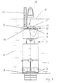
Figur 1- zeigt eine erste Ausführungsform einer erfindungsgemäßen Spüleinrichtung für einen WC-Spülkasten in Ruhestellung;
Figur 2- zeigt die in
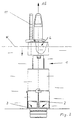
Figur 1 dargestellte erfindungsgemäße Spüleinrichtung bei Auslösung der großen Spülwassermenge; Figur 3- zeigt die in
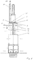
Figur 1 dargestellte erfindungsgemäße Spüleinrichtung bei Auslösung der kleinen Spülwassermenge; Figur 4- zeigt eine zweite Ausführungsform einer erfindungsgemäßen Spüleinrichtung in Ruhestellung;
Figur 5- zeigt die in
Figur 4 dargestellte erfindungsgemäße Spüleinrichtung bei Auslösung der kleinen Spülwassermenge; und - Figur 6
- zeigt die in den
Figuren 4 und 5 dargestellte zweite Ausführungsform der Erfindung in einer perspektivischen Teilansicht.
- Figure 1
- shows a first embodiment of a flushing device according to the invention for a toilet cistern in the rest position;
- Figure 2
- shows the flushing device according to the invention shown in Figure 1 when triggering the large amount of flushing water;
- Figure 3
- shows the flushing device according to the invention shown in Figure 1 when the small amount of flushing water is triggered;
- Figure 4
- shows a second embodiment of a flushing device according to the invention in the rest position;
- Figure 5
- shows the flushing device according to the invention shown in Figure 4 when triggering the small amount of flushing water; and
- Figure 6
- shows the second embodiment of the invention shown in Figures 4 and 5 in a perspective partial view.
In Figur 1 ist die erfindungsgemäße Spüleinrichtung in Ruhestellung dargestellt.In Figure 1, the flushing device according to the invention is shown in the rest position.
Ein Ventilteller 2 eines Ablaufventilkörpers 1 ruht auf einem Ventilsitz 3 und verhindert das Auslaufen des Spülwassers 4 aus einem (nicht dargestellten) Spülkasten. Um den oberen Bereich des Ablaufventilkörpers 1 ist ein im wesentlichen ringförmiges, nach unten hin offenes Wassergefäß 7 fest angeordnet. Infolge eines im nach oben weisenden Wandbereich des Wassergefäßes 7 in Ruhestellung stets offenen, eine Belüftungsöffnung 8 sowie einen Schwenkhebel 12 mit einer daran angeordneten Ventilklappe 10 umfassenden Belüftungsventiles 13 wird beim Füllen des Spülkastens eventuell im Wassergefäß 7 befindliche Luft durch die Belüftungsöffnung 8 herausgedrückt, so daß das Wassergefäß 7 in Ruhestellung vollständig mit Wasser gefüllt ist.A
Bei der in Figur 2 dargestellten Auslösung AG der großen Spülwassermenge wird durch das entsprechende (nicht dargestellte) Bedienelement für die große Spülwassermenge der Ablaufventilkörper 1 nach oben gezogen und der Ventilteller 2 vom Ventilsitz 3 abgehoben. Dadurch läuft das Spülwasser aus dem Spülkasten ab, wodurch der Wasserspiegel W im Spülkasten sinkt. Mit dem Sinken des Wasserspiegels W im Spülkasten läuft auch das im Wassergefäß 7 befindliche Wasser aus, weil die atmosphärische Luft L durch das offene Belüftungsventil 13 nachströmen kann. Dadurch vergrößert sich der Gesamtauftrieb des Ablaufventilkörpers 1, und dieser wird schwimmend gehalten, bis der Spülkasten völlig leergelaufen ist, und der Ventilteller 2 wieder auf dem Ventilsitz 3 aufsetzt und das Ablaufventil für die neue Füllung des Spülkastens, die von einem Zulaufventil gesteuert wird, verschließt.In the case of triggering AG of the large flushing water quantity shown in FIG. 2, the
Wie bereits dargelegt, wird auch bei der erneuten Füllung infolge des in Ruhestellung stets offenen Belüftungsventiles 13, durch welches sämtliche im Wasserbehälter befindliche Luft L verdrängt wird, der Wasserbehälter 7 wieder vollständig mit Wasser gefüllt.As already explained, the water container 7 is again completely filled with water even when it is refilled due to the ventilation valve 13 which is always open in the rest position and through which all air L in the water container is displaced.
Bei der in Figur 3 dargestellten Auslösung AK der kleinen Spülwassermenge zieht das entsprechende (nicht dargestellte) Bedienelement für die kleinere Spülwassermenge an einer seitlich und parallel zum Ablaufventilkörper 1 angeordneten Zugstange 11. Diese Zugstange 11 ist im Ablaufventilkörper 1 bzw. im Wassergefäß 7, parallel zur Achse des Ablaufventilkörpers 1 in der Weise verschieblich gelagert, daß sie sich zunächst relativ zum Ablaufventilkörper nach oben bewegt ohne den Ablaufventilkörper 1 mitzuziehen und dabei, z. B. über einen seitlich vorstehenden Zugflansch 21, der an der Unterseite des einen Armes 9 des Schwenkhebels 12 des Belüftungsventiles 13 angreift, den Arm 9 des Schwenkhebels 12 nach oben zieht und dadurch die am anderen Arm 5 des Schwenkhebels 12 befindliche Ventilklappe 10 auf die Belüftungsöffnung 8 drückt und somit das Belüftungsventil 13 schließt. Durch weiteres Ziehen an der Zugstange 11 wird nunmehr, unter dichtem Zuhalten des Belüftungsventiles 13, der Ablaufventilkörper 1 mit nach oben gezogen und dadurch der Ventilteller 2 des Ablaufventiles vom Ventilsitz 3 abgehoben. Das Spülwasser beginnt, aus dem Spülkasten abzulaufen. Im Unterschied zur Auslösung der großen Spülwassermenge kann jedoch beim Absinken des Wasserstandes W im Spülkasten infolge des geschlossenen Belüftungsventiles 13, kein Wasser aus dem Wassergefäß 7 abfließen. Dadurch ist der Gesamtauftrieb des Ablaufventilkörpers 1 vermindert, und der Ventilteller 2 setzt auf dem Ventilsitz 3 auf, bevor die Gesamtmenge des Spülwassers aus dem Spülkasten abgeflossen ist. Das Belüftungsventil 13 bleibt infolge des Soges des im Wassergefäß 7 befindlichen Wassers solange geschlossen, bis der Wasserspiegel W im Spülkasten wieder den im Wassergefäß 7 vorhandenen Wasserstand überschreitet. Dann ist im Wassergefäß 7 kein Sog mehr vorhanden und die Ventilklappe 10 hebt, nachdem die Zugstange 11 nach Loslassen des Bedienelementes wieder in ihre Ruhestellung zurückgeglitten ist, z. B. durch das Eigengewicht des gegenüberliegenden Armes 9 des Schwenkhebels 12 oder auch durch die Wirkung einer definierten Federkraft, wieder von der Belüftungsöffnung 8 ab, und nimmt dadurch die für eine erneute wahlweise Auslösung einer kleinen oder einer großen Spülwassermenge erforderliche Ruhestellung des Ablaufventiles 1 mit geöffnetem Belüftungsventil 13 ein.When triggering AK of the small amount of flushing water shown in FIG. 3, the corresponding control element (not shown) pulls the
In einer weiteren, in den Figuren 4, 5 und 6 dargestellten, besonders vorteilhaften Ausführungsform der Erfindung ist am Führungsteil 15 für den Ablaufventilkörper 1 ein senkrecht nach oben stehender Stellstift 16 fest angeordnet, welcher in einem im Wassergefäß 7 angeordneten, geschlossenen Kanal 17 mit Spielpassung verschiebbar ist. Im Ruhezustand der Spüleinrichtung ragt der Stellstift 16 durch den im Wassergefäß 7 angeordneten geschlossenen Kanal 17 hindurch, über die obere Fläche des nach oben weisenden Wandbereiches des Wassergefäßes 7 hinaus, und hebt den mit der Ventilklappe 10 versehenen Arm 5 des Schwenkhebels 12 von der Belüftungsöffnung ab. Außerdem ist mit dem Lager 19 des Schwenkhebels 12 ein Bremselement 20 verbunden, welches dem Lager 19 eine gewisse Schwergängigkeit verleiht und verhindert, daß der Schwenkhebel 12 durch zufällige geringe Kraftwirkungen, z. B. durch Erschütterungen usw., verstellt werden kann.In a further, particularly advantageous embodiment of the invention shown in FIGS. 4, 5 and 6, on the
Bei der Auslösung der großen Spülwassermenge AG wird, wie in Figur 2 dargestellt, der Ablaufventilkörper 1 nach oben gezogen. Dadurch hebt der Ventilteller 2 vom Ventilsitz 3 ab. Gleichzeitig zieht sich infolge der durch die Auslösung bewirkten Relativbewegung zwischen dem Ablaufventilkörper 1 und dem im Spülkasten verankerten Führungsteil 15 der Stellstift 16 aus seiner durch den geschlossenen Kanal 17 im Wassergefäß 7 hindurchragenden obersten Stellung zurück. Durch die Wirkung des Bremselementes 20 wird das Belüftungsventil 13 weiterhin gesichert offengehalten, so daß beim Absinken des Wasserspiegels W (siehe Figur 2) die atmosphärische Luft L durch das Belüftungsventil in das Wassergefäß 7 einströmen und dadurch das Wasser aus dem Wassergefäß austreten kann. Dadurch erhöht sich der Gesamtauftrieb des Ablaufventilkörpers in der Weise, daß die gesamte im Spülkasten enthaltene Wassermenge abfließen kann, bevor das Ablaufventil wieder schließt. Beim Schließen des Ablaufventils kehrt der Ablaufventilkörper 1 wieder in die in Figur 4 dargestellte Ruhestellung zurück und nach erneuter Füllung des Spülkastens ist dieser wieder zur wahlweisen Auslösung des Ablaufes einer bestimmten größeren oder kleineren Spülwassermenge bereit.When the large flushing water quantity AG is triggered, the
Die Auslösung der kleinen Spülwassermenge bei dieser Ausführungsform der Erfindung, bei der das Belüftungsventil unter Mitwirkung des Stellstiftes 16 gesteuert wird, ist in Figur 5 dargestellt.The triggering of the small amount of flushing water in this embodiment of the invention, in which the ventilation valve is controlled with the assistance of the
Durch Betätigung des Auslösers für die kleine Spülwassermenge wird die im Wassergefäß 7 verschieblich gelagerte Zugstange 11 nach oben gezogen. Ein an der Zugstange 11 angeordneter Zugflansch 21 greift quer zur Zugrichtung, z. B. über einen aus dem Hebelarm 9 seitlich vorstehenden Betätigungsstift 22, am Hebelarm 9 des Schwenkhebels 12 von unten an und zieht den Hebelarm 9 nach oben. Dadurch wird nicht nur der gesamte Ablaufventilkörper 1 mit nach oben gezogen sondern auch der Schwenkhebel 12 in der Weise verschwenkt, daß der gegenüberliegende Hebelarm 5 mit der Ventilklappe 10 nach unten schwenkt und die Belüftungsöffnung 8 verschließt. Dies ist möglich, weil beim Hochziehen des Ablaufventilkörpers 1 eine Relativbewegung zwischen dem Ablaufventilkörper 1 und dem im Spülkasten verankerten Führungsteil 15 eintritt, und der vom Führungsteil 15 senkrecht nach oben ragende Stellstift 16 sich aus seiner durch den geschlossenen Kanal 17 im Wassergefäß 7 hindurchragenden obersten Stellung zurückzieht und somit der Hebelarm 5 durch den Stellstift 16 nicht mehr in der abgehobenen Stellung gehalten wird. Die vom Bremselement 20 auf das Lager 19 ausgeübte Bremskraft, die ein Verschwenken des unbelasteten Schwenkhebels 12 bei der Auslösung der großen Spülwassermenge durch zufällige Kräfte, z. B. Erschütterungen usw. verhindert, wird durch die von der Zugstange 11 auf den Arm 9 des Schwenkhebels 12 von unten ausgeübte ungleich größere Zugkraft überwunden, und der Arm 9 wird nach oben gezogen, wodurch der Arm 5 mit der Ventilklappe 10 auf die Belüftungsöffnung 8 gedrückt und auch nach Beendigung der Einwirkung der Zugkraft AK durch die Bremswirkung des Bremselementes 20 und durch die Saugwirkung des im Wassergefäß 7 befindlichen Wassers in dieser Stellung gehalten wird. Durch das im Wassergefäß 7 gehaltene Wasser wird der Gesamtauftrieb des Ablaufventilkörpers um einen definierten Betrag vermindert und dadurch nach Ablauf einer bestimmten Spülwassermenge, bevor die gesamte Spülwassermenge abgelaufen ist, das Auflaufventil 2, 3 wieder geschlossen. Beim Erreichen der Schließstellung des Ablaufventiles 2, 3 nimmt auch der Ablaufventilkörper wieder seine Ruhestellung ein, d. h. der auf dem Führungsteil 15 senkrecht nach oben stehende Stellstift 16 durchdringt wieder den geschlossenen Kanal 17 im Wassergefäß 7 und ragt aus diesem hervor, so daß seine Spitze den Arm 5 des Belüftungsventils wieder in die von der Belüftungsöffnung 8 abgehobene Stellung drückt.By actuating the trigger for the small amount of flushing water, the
Nach erneuter Füllung des Spülkastens, welche in bekannter Weise von einem speziellen Zulaufventil gesteuert wird, ist die erfindungsgemäße Spüleinrichtung wieder zur wahlweisen Auslösung einer bestimmten größeren oder kleineren Spülwassermenge mittels der separaten Bedienelemente bereit.After refilling the cistern, which is controlled in a known manner by a special inlet valve, the flushing device according to the invention is again ready to selectively trigger a certain larger or smaller amount of flushing water by means of the separate operating elements.
Figur 6 veranschaulicht in einer perspektivischen Teilansicht einige in den übrigen Figuren nicht dargestellte Details der erfindungsgemäßen Spüleinrichtung, so z. B., daß der Stellstift 16 nicht unmittelbar an der Unterseite des Hebelarmes 5 des Schwenkhebels 12 angreift, sondern an der Unterseite eines mit dem Hebelarm 5 verbundenen, parallel zur Unterseite des Hebelarmes 5 seitlich vorstehenden Betätigungsflansches 18, wodurch auf allzu enge Maßtoleranzen für das Zusammenspiel beider Teile verzichtet werden kann.Figure 6 illustrates in a partial perspective view some details of the flushing device according to the invention, not shown in the remaining figures, such. B. that the
Weiterhin ist erkennbar, daß an der Zugstange 11 der quer zur Zugrichtung vorstehende Zugflansch 21 angeordnet ist, der mit dem Hebelarm 9 des Schwenkhebels 12 über den aus dem Hebelarm 9 quer zur Längsachse des Schwenkhebels 12 vorstehenden Betätigungsstift 22 zusammenwirkt.Furthermore, it can be seen that the
Schließlich ist noch eine mögliche Ausführungsform des Bremselementes 20 erkennbar. Das Bremselement 20 ist als federndes Element, z. B. aus elastischem Kunststoff ausgebildet, das radial auf eine kreissegmentförmige Ausbildung des Schwenkhebels 12 über dem Lager 19 drückt. Durch ein solches Bremselement 20 wird die Lagerreibung im Lager 19 erhöht, und es wird verhindert, daß sich der Schwenkhebel, wenn er in Funktion zeitweilig nicht vom Stellstift 16 oder dem Zughebel 11 betätigt wird, durch zufällig wirkende Kräfte, z. B. durch Erschütterungen usw. verstellt.Finally, a possible embodiment of the
In den Figuren nicht dargestellt sind folgende vorteilhaften Ausführungsformen der Erfindung: Das Wassergefäß 7 bildet mit dem Schwenkhebel 12 und der in einem am Wassergefäß 7 angeordneten Gleitlager verschieblich gelagerten Zugstange 11 sowie gegebenenfalls mit dem geschlossenen Kanal 17 eine Baugruppe, welche vom Ablaufventilkörper 1 völlig getrennt gefertigt wird, und mit diesem durch eine einfache Snap-in-Verbindung verrastbar ist. Dadurch ist es möglich, zum einen die bekannten Standard-Ablaufventilkörper (ohne Zweimengenspülung) zu fertigen und diese andererseits durch einfaches Verrasten der erwähnten zusätzlichen Baugruppen auch für Zweimengen-Spüleinrichtungen einsetzen zu können. Dies vermindert die Fertigungs-, Lagerhaltungs- und Vertriebskosten beträchtlich.The following advantageous embodiments of the invention are not shown in the figures: The water vessel 7 forms a subassembly with the
Weiterhin ist es vorteilhaft das Gleitlager für die Zugstange 11 bzw. die Zugstange 11 selbst mit einem Anschlag oder mehreren Anschlägen zu versehen, welche die Gleitbewegung der Zugstange 11 im Gleitlager auf das Maß begrenzen, welches erforderlich ist, um den Arm 9 des Schwenkhebels 12 soweit nach oben zu ziehen, daß die Ventilklappe 10 die Belüftungsöffnung 8 fest verschließt. Durch einen solchen Anschlag im Gleitlager und/oder an der Zugstange 11 wird vermieden, daß die gesamte zum Abheben des Ablaufventilkörpers 1 erforderliche Kraft auf die Mitnehmereinrichtung an der Zugstange 11 zum Anheben des Schwenkhebelarmes 9 sowie auf das Lager 13 des Schwenkhebels 12 wirkt und dort eine Bruchgefahr oder einen erhöhten Verschleiß herbeiführt.Furthermore, it is advantageous to provide the slide bearing for the
Die erfindungsgemäße Spüleinrichtung hat den Vorteil, daß sie einen einfachen Aufbau aufweist und im Vergleich zu den bekannten Spüleinrichtungen mit separaten Bedienelementen zur wahlweisen Auslösung des Ablaufes einer bestimmten größeren oder kleineren Spülwassermenge wesentlich weniger störanfällig ist.The flushing device according to the invention has the advantage that it has a simple structure and is much less susceptible to faults in comparison to the known flushing devices with separate operating elements for optionally triggering the flow of a certain larger or smaller amount of flushing water.
Claims (11)
Applications Claiming Priority (2)
| Application Number | Priority Date | Filing Date | Title |
|---|---|---|---|
| DE29807875U DE29807875U1 (en) | 1998-05-06 | 1998-05-06 | Flushing device for a toilet cistern |
| DE29807875U | 1998-05-06 |
Publications (3)
| Publication Number | Publication Date |
|---|---|
| EP0955417A2 true EP0955417A2 (en) | 1999-11-10 |
| EP0955417A3 EP0955417A3 (en) | 2000-04-26 |
| EP0955417B1 EP0955417B1 (en) | 2003-11-19 |
Family
ID=8056556
Family Applications (1)
| Application Number | Title | Priority Date | Filing Date |
|---|---|---|---|
| EP99108918A Expired - Lifetime EP0955417B1 (en) | 1998-05-06 | 1999-05-05 | Flushing device for a toilet flushing cistern |
Country Status (3)
| Country | Link |
|---|---|
| EP (1) | EP0955417B1 (en) |
| DE (2) | DE29807875U1 (en) |
| ES (1) | ES2209273T3 (en) |
Cited By (2)
| Publication number | Priority date | Publication date | Assignee | Title |
|---|---|---|---|---|
| WO2002001010A1 (en) * | 2000-06-27 | 2002-01-03 | Blackborow, John | Dual discharge valve |
| WO2002048472A3 (en) * | 2000-12-15 | 2002-08-29 | Dutton Plastics Engineering Pt | Toilet cistern dual flush valve |
Families Citing this family (1)
| Publication number | Priority date | Publication date | Assignee | Title |
|---|---|---|---|---|
| DE102006051823A1 (en) * | 2006-11-03 | 2008-05-08 | Tece Gmbh | Dual flush discharge valve |
Citations (2)
| Publication number | Priority date | Publication date | Assignee | Title |
|---|---|---|---|---|
| DE29517393U1 (en) | 1995-11-03 | 1996-02-01 | Hohmann, Claas, Dr.med., 78315 Radolfzell | Pericardial prosthesis |
| EP0723050A1 (en) | 1995-01-18 | 1996-07-24 | Friatec Aktiengesellschaft Keramik- und Kunststoffwerke | Drainage device of a flushing cistern |
Family Cites Families (5)
| Publication number | Priority date | Publication date | Assignee | Title |
|---|---|---|---|---|
| EP0539483A1 (en) * | 1990-07-19 | 1993-05-05 | Antonius Franciscus Veldhoven | Improvements in and relating to water closet cisterns |
| US5070547A (en) * | 1990-11-29 | 1991-12-10 | Joseph Comparetti | Dual handle semi-flush retrofit kit |
| GB9215689D0 (en) * | 1992-07-23 | 1992-09-09 | Mckenzie Martin S | Toilet syphon |
| AU7690396A (en) * | 1995-12-20 | 1997-07-14 | Alliance Invest Ag | Device for a cistern |
| CH692301A5 (en) | 1997-11-04 | 2002-04-30 | Geberit Technik Ag | Two volumes-Spülgarnitur for a cistern. |
-
1998
- 1998-05-06 DE DE29807875U patent/DE29807875U1/en not_active Expired - Lifetime
-
1999
- 1999-05-05 ES ES99108918T patent/ES2209273T3/en not_active Expired - Lifetime
- 1999-05-05 EP EP99108918A patent/EP0955417B1/en not_active Expired - Lifetime
- 1999-05-05 DE DE59907766T patent/DE59907766D1/en not_active Expired - Lifetime
Patent Citations (2)
| Publication number | Priority date | Publication date | Assignee | Title |
|---|---|---|---|---|
| EP0723050A1 (en) | 1995-01-18 | 1996-07-24 | Friatec Aktiengesellschaft Keramik- und Kunststoffwerke | Drainage device of a flushing cistern |
| DE29517393U1 (en) | 1995-11-03 | 1996-02-01 | Hohmann, Claas, Dr.med., 78315 Radolfzell | Pericardial prosthesis |
Cited By (4)
| Publication number | Priority date | Publication date | Assignee | Title |
|---|---|---|---|---|
| WO2002001010A1 (en) * | 2000-06-27 | 2002-01-03 | Blackborow, John | Dual discharge valve |
| US6874172B2 (en) | 2000-06-27 | 2005-04-05 | Douglas Robert David Frost | Dual discharge valve |
| AU785390B2 (en) * | 2000-06-27 | 2007-03-29 | Blackborow, John | Dual discharge valve |
| WO2002048472A3 (en) * | 2000-12-15 | 2002-08-29 | Dutton Plastics Engineering Pt | Toilet cistern dual flush valve |
Also Published As
| Publication number | Publication date |
|---|---|
| ES2209273T3 (en) | 2004-06-16 |
| DE59907766D1 (en) | 2003-12-24 |
| DE29807875U1 (en) | 1998-07-16 |
| EP0955417B1 (en) | 2003-11-19 |
| EP0955417A3 (en) | 2000-04-26 |
Similar Documents
| Publication | Publication Date | Title |
|---|---|---|
| EP0479716B1 (en) | Actuator for the discharge valve of a flush cistern | |
| EP0722020B1 (en) | Flushing device in a flushing tank | |
| DE69517392T2 (en) | Sink device for water closets | |
| DE2508752A1 (en) | WATER FLUSHING MECHANISM | |
| DE9215972U1 (en) | Cistern drain valve | |
| EP2092128B1 (en) | Two-quantity discharge valve | |
| EP0955417A2 (en) | Flushing device for a toilet flushing cistern | |
| EP0683276A2 (en) | Flushing device for a water closet | |
| EP1672130B1 (en) | Flush device for a lavatory flush tank | |
| EP0529237B1 (en) | Flushing-device | |
| EP1537277B1 (en) | Flushing device comprising a pressurized chamber, evacuation fitting for a flushing device, and system comprising a flushing device and a toilet bowl | |
| WO2014124788A1 (en) | Drain assembly for a flushing tank | |
| EP1010826B1 (en) | Outlet device for a flushing cistern | |
| EP1580338B1 (en) | Flush valve for a flushing cistern | |
| DE2611604C2 (en) | Device for limiting the flow of water from water tanks with a floor outlet | |
| DE3106764A1 (en) | "TOILET SINK" | |
| EP0859093B1 (en) | Outlet device for a toilet flush tank with selective full or partial flush | |
| DE69105268T2 (en) | Push-button flush mechanism with submersible body. | |
| EP0185940A2 (en) | Toilet flushing reservoir | |
| DE2626053A1 (en) | DEVICE FOR THE CONVERSION OF A FLUSHBOX OF FIXED VOLUME INTO A FLUSHBOX WITH CHANGEABLE VOLUME | |
| DE8105070U1 (en) | "TOILET SINK" | |
| DE3121625A1 (en) | Flushing cistern for sanitary facilities, such as WC bowls or the like | |
| DE4116672A1 (en) | Water separator for pneumatic installation - has operation of float actuated valve assisted by spring | |
| DE8434369U1 (en) | WC - cistern | |
| DD268265A1 (en) | TWO-STAGE WATER DOSING DEVICE FOR WC COIL CHEST |
Legal Events
| Date | Code | Title | Description |
|---|---|---|---|
| PUAI | Public reference made under article 153(3) epc to a published international application that has entered the european phase |
Free format text: ORIGINAL CODE: 0009012 |
|
| AK | Designated contracting states |
Kind code of ref document: A2 Designated state(s): DE ES FR GB IT |
|
| AX | Request for extension of the european patent |
Free format text: AL;LT;LV;MK;RO;SI |
|
| PUAL | Search report despatched |
Free format text: ORIGINAL CODE: 0009013 |
|
| AK | Designated contracting states |
Kind code of ref document: A3 Designated state(s): AT BE CH CY DE DK ES FI FR GB GR IE IT LI LU MC NL PT SE |
|
| AX | Request for extension of the european patent |
Free format text: AL;LT;LV;MK;RO;SI |
|
| RAP1 | Party data changed (applicant data changed or rights of an application transferred) |
Owner name: ETEX SOCIETE ANONYME |
|
| 17P | Request for examination filed |
Effective date: 20000907 |
|
| AKX | Designation fees paid |
Free format text: DE ES FR GB IT |
|
| RAP1 | Party data changed (applicant data changed or rights of an application transferred) |
Owner name: ETEX PLASTICS |
|
| GRAH | Despatch of communication of intention to grant a patent |
Free format text: ORIGINAL CODE: EPIDOS IGRA |
|
| GRAS | Grant fee paid |
Free format text: ORIGINAL CODE: EPIDOSNIGR3 |
|
| GRAA | (expected) grant |
Free format text: ORIGINAL CODE: 0009210 |
|
| RAP1 | Party data changed (applicant data changed or rights of an application transferred) |
Owner name: ALIAXIS PARTICIPATIONS |
|
| AK | Designated contracting states |
Kind code of ref document: B1 Designated state(s): DE ES FR GB IT |
|
| REG | Reference to a national code |
Ref country code: GB Ref legal event code: FG4D Free format text: NOT ENGLISH |
|
| REF | Corresponds to: |
Ref document number: 59907766 Country of ref document: DE Date of ref document: 20031224 Kind code of ref document: P |
|
| GBT | Gb: translation of ep patent filed (gb section 77(6)(a)/1977) |
Effective date: 20040128 |
|
| REG | Reference to a national code |
Ref country code: ES Ref legal event code: FG2A Ref document number: 2209273 Country of ref document: ES Kind code of ref document: T3 |
|
| ET | Fr: translation filed | ||
| PLBE | No opposition filed within time limit |
Free format text: ORIGINAL CODE: 0009261 |
|
| STAA | Information on the status of an ep patent application or granted ep patent |
Free format text: STATUS: NO OPPOSITION FILED WITHIN TIME LIMIT |
|
| 26N | No opposition filed |
Effective date: 20040820 |
|
| REG | Reference to a national code |
Ref country code: DE Ref legal event code: R082 Ref document number: 59907766 Country of ref document: DE Representative=s name: 24IP LAW GROUP SONNENBERG FORTMANN, DE |
|
| REG | Reference to a national code |
Ref country code: FR Ref legal event code: PLFP Year of fee payment: 18 |
|
| REG | Reference to a national code |
Ref country code: FR Ref legal event code: PLFP Year of fee payment: 19 |
|
| PGFP | Annual fee paid to national office [announced via postgrant information from national office to epo] |
Ref country code: FR Payment date: 20170524 Year of fee payment: 19 Ref country code: GB Payment date: 20170519 Year of fee payment: 19 |
|
| PGFP | Annual fee paid to national office [announced via postgrant information from national office to epo] |
Ref country code: ES Payment date: 20170601 Year of fee payment: 19 Ref country code: IT Payment date: 20170524 Year of fee payment: 19 |
|
| PGFP | Annual fee paid to national office [announced via postgrant information from national office to epo] |
Ref country code: DE Payment date: 20170718 Year of fee payment: 19 |
|
| REG | Reference to a national code |
Ref country code: DE Ref legal event code: R119 Ref document number: 59907766 Country of ref document: DE |
|
| GBPC | Gb: european patent ceased through non-payment of renewal fee |
Effective date: 20180505 |
|
| PG25 | Lapsed in a contracting state [announced via postgrant information from national office to epo] |
Ref country code: DE Free format text: LAPSE BECAUSE OF NON-PAYMENT OF DUE FEES Effective date: 20181201 Ref country code: IT Free format text: LAPSE BECAUSE OF NON-PAYMENT OF DUE FEES Effective date: 20180505 Ref country code: FR Free format text: LAPSE BECAUSE OF NON-PAYMENT OF DUE FEES Effective date: 20180531 Ref country code: GB Free format text: LAPSE BECAUSE OF NON-PAYMENT OF DUE FEES Effective date: 20180505 |
|
| REG | Reference to a national code |
Ref country code: ES Ref legal event code: FD2A Effective date: 20190913 |
|
| PG25 | Lapsed in a contracting state [announced via postgrant information from national office to epo] |
Ref country code: ES Free format text: LAPSE BECAUSE OF NON-PAYMENT OF DUE FEES Effective date: 20180506 |