EP0955417A2 - Dispositif de chasse pour une chasse d'eau - Google Patents
Dispositif de chasse pour une chasse d'eau Download PDFInfo
- Publication number
- EP0955417A2 EP0955417A2 EP99108918A EP99108918A EP0955417A2 EP 0955417 A2 EP0955417 A2 EP 0955417A2 EP 99108918 A EP99108918 A EP 99108918A EP 99108918 A EP99108918 A EP 99108918A EP 0955417 A2 EP0955417 A2 EP 0955417A2
- Authority
- EP
- European Patent Office
- Prior art keywords
- arm
- lever
- water
- valve
- flushing
- Prior art date
- Legal status (The legal status is an assumption and is not a legal conclusion. Google has not performed a legal analysis and makes no representation as to the accuracy of the status listed.)
- Granted
Links
Images


Classifications
-
- E—FIXED CONSTRUCTIONS
- E03—WATER SUPPLY; SEWERAGE
- E03D—WATER-CLOSETS OR URINALS WITH FLUSHING DEVICES; FLUSHING VALVES THEREFOR
- E03D1/00—Water flushing devices with cisterns ; Setting up a range of flushing devices or water-closets; Combinations of several flushing devices
- E03D1/02—High-level flushing systems
- E03D1/14—Cisterns discharging variable quantities of water also cisterns with bell siphons in combination with flushing valves
- E03D1/142—Cisterns discharging variable quantities of water also cisterns with bell siphons in combination with flushing valves in cisterns with flushing valves
Definitions
- the invention relates to a flushing device for a toilet cistern, with separate controls for optionally triggering the flow of a certain larger or smaller amount of flushing water.
- flushing devices which are also referred to as dual-flush devices, are e.g. B. from the European patent application EP 0 723 050 A1, the German utility model DE 295 17 393 U1 and the patent application PCT / EP91 / 01374 known.
- a two-quantity flushing device which uses a drain valve common in toilet cisterns, in which a valve disc is lifted from a valve seat located at the outlet in the bottom of the cistern by lifting the drain valve body and kept lifted for at least one float by the buoyancy effect until the cistern is completely emptied.
- two floats are provided, one of which is fixed and the other detachably connected to the drain valve body. When triggered the large amount of flushing water, both floats are connected to the drain valve body.
- German utility model DE 295 17 393 U1 when the small amount of flushing water is triggered, the buoyancy of the drain valve body is reduced and the drain valve is closed again after a certain amount of partial flushing water has expired. This is done by an additional weight body with which the drain valve body is locked via a swivel lever gear when the small amount of flushing water is triggered. The additional weight body counteracts the buoyancy of the float and presses the valve plate back onto the valve seat of the drain valve before the total amount of flushing water contained in the cistern runs out.
- the different buoyancy of the drain valve body when a larger or a smaller amount of flushing water is triggered is controlled by a loading bell that is firmly connected to the drain valve body and can be filled with water, which bell, depending on whether the flushing process is triggered and After lifting the valve plate from the valve seat, air can enter the load bell from the outside or not, the drain valve body either remains heavy due to the water filling of the load bell and thereby the drain valve closes prematurely, or the buoyancy increases due to the penetration of air, and thereby the drain valve is kept open until all of the flushing water in the cistern has run out.
- the air is supplied to the bell via a flexible, coiled hose that goes from the inside of the load bell to the outside of the Cistern leads.
- a ventilation valve combined with the trigger button for lifting the drain valve. This is always open in the rest position.
- the bell can always run full of water when filling the cistern because any air in the bell can be displaced to the outside through the hose.
- a rocker arm is pressed in one direction in this flushing device, whereby only the drain valve body is raised, but the ventilation valve remains open.
- the invention is therefore based on the object of providing a flushing device for a toilet cistern with separate control elements for triggering the outflow of a certain larger or smaller amount of flushing water, which is uncomplicated in structure and less susceptible to faults.
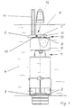
- a valve plate 2 of a drain valve body 1 rests on a valve seat 3 and prevents the rinsing water 4 from escaping from a cistern (not shown).
- An essentially annular, downwardly open water vessel 7 is fixedly arranged around the upper region of the drain valve body 1.
- a ventilation valve 13 which is always open in the rest position in the upwardly facing wall region of the water vessel 7 and comprises a ventilation opening 8 and a pivoting lever 12 with a valve flap 10 arranged thereon, any air in the water vessel 7 is pushed out through the ventilation opening 8 when the cistern is filled, so that the water vessel 7 is completely filled with water in the rest position.
- the water container 7 is again completely filled with water even when it is refilled due to the ventilation valve 13 which is always open in the rest position and through which all air L in the water container is displaced.
- the corresponding control element pulls the pulling rod 11 arranged laterally and parallel to the drain valve body 1 for the smaller flushing water amount.
- This pull rod 11 is in the drain valve body 1 or in the water vessel 7, parallel to Axis of the drain valve body 1 is slidably mounted in such a way that it first moves upward relative to the drain valve body without pulling the drain valve body 1 and thereby, for. B.
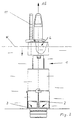
- the ventilation valve 13 remains closed due to the suction of the water in the water vessel 7 until until the water level W in the cistern again exceeds the water level in the water container 7. Then there is no more suction in the water vessel 7 and the valve flap 10 lifts after the pull rod 11 has slid back into its rest position after releasing the control element, e.g. B.
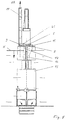
- a fixed upright adjusting pin 16 which in a closed channel 17 arranged in the water vessel 7 with clearance fit is movable.
- the actuating pin 16 protrudes through the closed channel 17 arranged in the water vessel 7, beyond the upper surface of the upwardly facing wall region of the water vessel 7, and lifts the arm 5 of the pivoting lever 12 provided with the valve flap 10 from the ventilation opening .
- a brake element 20 is connected to the bearing 19 of the pivot lever 12, which gives the bearing 19 a certain stiffness and prevents the pivot lever 12 from accidental small forces, z. B. can be adjusted by vibrations, etc.
- the drain valve body 1 When the large flushing water quantity AG is triggered, the drain valve body 1 is pulled upward, as shown in FIG. As a result, the valve plate 2 lifts off the valve seat 3. At the same time, as a result of the relative movement caused by the release between the drain valve body 1 and the guide part 15 anchored in the cistern, the actuating pin 16 withdraws from its uppermost position which projects through the closed channel 17 in the water vessel 7. Due to the action of the braking element 20, the ventilation valve 13 is still securely kept open, so that when the water level W (see FIG. 2) drops, the atmospheric air L can flow into the water vessel 7 through the ventilation valve and the water can thereby escape from the water vessel.
- FIG. 5 The triggering of the small amount of flushing water in this embodiment of the invention, in which the ventilation valve is controlled with the assistance of the actuating pin 16, is shown in FIG. 5.
- the pull rod 11 By actuating the trigger for the small amount of flushing water, the pull rod 11, which is displaceably mounted in the water vessel 7, is pulled upward.
- the pivot lever 12 is pivoted in such a way that the opposite lever arm 5 pivots with the valve flap 10 downward and closes the ventilation opening 8.
- the drain valve 2, 3 also the drain valve body returns to its rest position, ie the control pin 16 standing vertically upwards on the guide part 15 penetrates again the closed channel 17 in the water vessel 7 and protrudes therefrom, so that its tip arm 5 of the ventilation valve presses again into the position lifted from the ventilation opening 8.
- the flushing device according to the invention After refilling the cistern, which is controlled in a known manner by a special inlet valve, the flushing device according to the invention is again ready to selectively trigger a certain larger or smaller amount of flushing water by means of the separate operating elements.
- Figure 6 illustrates in a partial perspective view some details of the flushing device according to the invention, not shown in the remaining figures, such. B. that the actuating pin 16 does not act directly on the underside of the lever arm 5 of the pivoting lever 12, but on the underside of an actuating flange 18 connected laterally to the underside of the lever arm 5 and parallel to the underside of the lever arm 5, which results in excessively narrow dimensional tolerances for the interaction both parts can be dispensed with.
- the pull flange 21 projecting transversely to the pulling direction is arranged on the pull rod 11 and cooperates with the lever arm 9 of the pivot lever 12 via the actuating pin 22 projecting from the lever arm 9 transversely to the longitudinal axis of the pivot lever 12.
- the braking element 20 is as a resilient element, for. B. made of elastic plastic that presses radially on a circular segment-shaped design of the pivot lever 12 above the bearing 19.
- the braking element 20 By such a braking element 20, the bearing friction in the bearing 19 is increased, and it is prevented that the pivot lever, if it is temporarily not operated by the actuating pin 16 or the pull lever 11 in operation, by randomly acting forces, e.g. B. adjusted by vibrations, etc.
- the water vessel 7 forms a subassembly with the pivot lever 12 and the pull rod 11, which is displaceably mounted in a slide bearing arranged on the water vessel 7, and optionally with the closed channel 17, which is manufactured completely separately from the drain valve body 1 and can be locked with it by a simple snap-in connection.
- the slide bearing for the pull rod 11 or the pull rod 11 itself with a stop or a plurality of stops, which limit the sliding movement of the pull rod 11 in the slide bearing to the extent required by the arm 9 of the pivot lever 12 as far as possible to pull up that the valve flap 10 closes the ventilation opening 8 firmly.
- a stop in the slide bearing and / or on the pull rod 11 it is avoided that the entire force required for lifting the drain valve body 1 acts on the driver device on the pull rod 11 for lifting the pivot lever arm 9 and on the bearing 13 of the pivot lever 12 and there one Risk of breakage or increased wear.
- the flushing device according to the invention has the advantage that it has a simple structure and is much less susceptible to faults in comparison to the known flushing devices with separate operating elements for optionally triggering the flow of a certain larger or smaller amount of flushing water.
Landscapes
- Health & Medical Sciences (AREA)
- Life Sciences & Earth Sciences (AREA)
- Engineering & Computer Science (AREA)
- Hydrology & Water Resources (AREA)
- Public Health (AREA)
- Water Supply & Treatment (AREA)
- Sanitary Device For Flush Toilet (AREA)
- Bidet-Like Cleaning Device And Other Flush Toilet Accessories (AREA)
- Float Valves (AREA)
- Self-Closing Valves And Venting Or Aerating Valves (AREA)
Applications Claiming Priority (2)
| Application Number | Priority Date | Filing Date | Title |
|---|---|---|---|
| DE29807875U | 1998-05-06 | ||
| DE29807875U DE29807875U1 (de) | 1998-05-06 | 1998-05-06 | Spüleinrichtung für einen WC-Spülkasten |
Publications (3)
| Publication Number | Publication Date |
|---|---|
| EP0955417A2 true EP0955417A2 (fr) | 1999-11-10 |
| EP0955417A3 EP0955417A3 (fr) | 2000-04-26 |
| EP0955417B1 EP0955417B1 (fr) | 2003-11-19 |
Family
ID=8056556
Family Applications (1)
| Application Number | Title | Priority Date | Filing Date |
|---|---|---|---|
| EP99108918A Expired - Lifetime EP0955417B1 (fr) | 1998-05-06 | 1999-05-05 | Dispositif de chasse pour une chasse d'eau |
Country Status (3)
| Country | Link |
|---|---|
| EP (1) | EP0955417B1 (fr) |
| DE (2) | DE29807875U1 (fr) |
| ES (1) | ES2209273T3 (fr) |
Cited By (2)
| Publication number | Priority date | Publication date | Assignee | Title |
|---|---|---|---|---|
| WO2002001010A1 (fr) * | 2000-06-27 | 2002-01-03 | Blackborow, John | Soupape de decharge double |
| WO2002048472A3 (fr) * | 2000-12-15 | 2002-08-29 | Dutton Plastics Engineering Pt | Robinet de chasse d'eau double de toilettes |
Families Citing this family (1)
| Publication number | Priority date | Publication date | Assignee | Title |
|---|---|---|---|---|
| DE102006051823A1 (de) * | 2006-11-03 | 2008-05-08 | Tece Gmbh | Zwei-Mengen-Ablaufventil |
Citations (2)
| Publication number | Priority date | Publication date | Assignee | Title |
|---|---|---|---|---|
| DE29517393U1 (de) | 1995-11-03 | 1996-02-01 | Hohmann, Claas, Dr.med., 78315 Radolfzell | Herzbeutelprothese |
| EP0723050A1 (fr) | 1995-01-18 | 1996-07-24 | Friatec Aktiengesellschaft Keramik- und Kunststoffwerke | Dispositif d'écoulement d'un réservoir de chasse d'eau |
Family Cites Families (5)
| Publication number | Priority date | Publication date | Assignee | Title |
|---|---|---|---|---|
| AU8232891A (en) * | 1990-07-19 | 1992-02-18 | Antonius Franciscus Veldhoven | Improvements in and relating to water closet cisterns |
| US5070547A (en) * | 1990-11-29 | 1991-12-10 | Joseph Comparetti | Dual handle semi-flush retrofit kit |
| GB9215689D0 (en) * | 1992-07-23 | 1992-09-09 | Mckenzie Martin S | Toilet syphon |
| AU7690396A (en) * | 1995-12-20 | 1997-07-14 | Alliance Invest Ag | Device for a cistern |
| CH692301A5 (de) | 1997-11-04 | 2002-04-30 | Geberit Technik Ag | Zweimengen-Spülgarnitur für einen Spülkasten. |
-
1998
- 1998-05-06 DE DE29807875U patent/DE29807875U1/de not_active Expired - Lifetime
-
1999
- 1999-05-05 ES ES99108918T patent/ES2209273T3/es not_active Expired - Lifetime
- 1999-05-05 DE DE59907766T patent/DE59907766D1/de not_active Expired - Lifetime
- 1999-05-05 EP EP99108918A patent/EP0955417B1/fr not_active Expired - Lifetime
Patent Citations (2)
| Publication number | Priority date | Publication date | Assignee | Title |
|---|---|---|---|---|
| EP0723050A1 (fr) | 1995-01-18 | 1996-07-24 | Friatec Aktiengesellschaft Keramik- und Kunststoffwerke | Dispositif d'écoulement d'un réservoir de chasse d'eau |
| DE29517393U1 (de) | 1995-11-03 | 1996-02-01 | Hohmann, Claas, Dr.med., 78315 Radolfzell | Herzbeutelprothese |
Cited By (4)
| Publication number | Priority date | Publication date | Assignee | Title |
|---|---|---|---|---|
| WO2002001010A1 (fr) * | 2000-06-27 | 2002-01-03 | Blackborow, John | Soupape de decharge double |
| US6874172B2 (en) | 2000-06-27 | 2005-04-05 | Douglas Robert David Frost | Dual discharge valve |
| AU785390B2 (en) * | 2000-06-27 | 2007-03-29 | Blackborow, John | Dual discharge valve |
| WO2002048472A3 (fr) * | 2000-12-15 | 2002-08-29 | Dutton Plastics Engineering Pt | Robinet de chasse d'eau double de toilettes |
Also Published As
| Publication number | Publication date |
|---|---|
| ES2209273T3 (es) | 2004-06-16 |
| DE59907766D1 (de) | 2003-12-24 |
| EP0955417B1 (fr) | 2003-11-19 |
| EP0955417A3 (fr) | 2000-04-26 |
| DE29807875U1 (de) | 1998-07-16 |
Similar Documents
| Publication | Publication Date | Title |
|---|---|---|
| EP0479716B1 (fr) | Dispositif d'actionnement d'un clapet de vidange d'un réservoir de chasse | |
| EP0722020B1 (fr) | Dispositif de chasse dans un réservoir de chasse d'eau | |
| DE69517392T2 (de) | Spüleeinrichtung für Wasserklosetts | |
| DE2508752A1 (de) | Wasserspuelungsmechanismus | |
| DE9215972U1 (de) | Spülkasten-Ablaufventil | |
| EP2092128B1 (fr) | Soupape d'évacuation à deux débits | |
| EP0955417A2 (fr) | Dispositif de chasse pour une chasse d'eau | |
| EP0683276A2 (fr) | Dispositif de chasse pour W.C. | |
| EP1672130B1 (fr) | Soupape d'évacuation d'un réservoir de chasse | |
| EP0529237B1 (fr) | Dispositif de chasse d'eau | |
| WO1990010759A1 (fr) | Procede et dispositif pour distribuer une quantite predeterminee d'un milieu fluide dans un recipient de liquide ou similaire | |
| EP1537277B1 (fr) | Dispositif de chasse d'eau comportant une cavite sous pression, robinetterie d'evacuation pour chasse d'eau et installation comprenant un dispositif de chasse d'eau et une cuve de chasse d'eau | |
| WO2014124788A1 (fr) | Mécanisme de chasse d'eau | |
| EP1010826B1 (fr) | Dispositif d'écoulement pour chasse d'eau | |
| EP1580338B1 (fr) | Clapet de vidange pour un réservoir de chasse d'eau | |
| DE2611604C2 (de) | Vorrichtung zur Begrenzung des Wasserauslaufes aus Wasserbehältern mit einem Bodenauslauf | |
| DE3106764A1 (de) | "toilettenspuelbecken" | |
| EP0859093B1 (fr) | Dispositif d'écoulement pour réservoir de chasse d'eau de toilette permettant sélectivement le rinçage complet ou partiel | |
| DE69105268T2 (de) | Druckknopfspülmechanismus mit eintauchbarem Körper. | |
| EP0185940A2 (fr) | Réservoir de chasse d'eau pour toilettes | |
| DE2626053A1 (de) | Vorrichtung zur umwandlung eines spuelkastens festen volumens in einen spuelkasten mit veraenderbarem volumen | |
| DE8105070U1 (de) | "toilettenspuelbecken" | |
| DE3121625A1 (de) | Spuelkasten fuer sanitaere einrichtungen, wie wc-becken o.dgl. | |
| DE4116672A1 (de) | Fluessigkeitsabscheider | |
| DE8434369U1 (de) | WC - Spülkasten |
Legal Events
| Date | Code | Title | Description |
|---|---|---|---|
| PUAI | Public reference made under article 153(3) epc to a published international application that has entered the european phase |
Free format text: ORIGINAL CODE: 0009012 |
|
| AK | Designated contracting states |
Kind code of ref document: A2 Designated state(s): DE ES FR GB IT |
|
| AX | Request for extension of the european patent |
Free format text: AL;LT;LV;MK;RO;SI |
|
| PUAL | Search report despatched |
Free format text: ORIGINAL CODE: 0009013 |
|
| AK | Designated contracting states |
Kind code of ref document: A3 Designated state(s): AT BE CH CY DE DK ES FI FR GB GR IE IT LI LU MC NL PT SE |
|
| AX | Request for extension of the european patent |
Free format text: AL;LT;LV;MK;RO;SI |
|
| RAP1 | Party data changed (applicant data changed or rights of an application transferred) |
Owner name: ETEX SOCIETE ANONYME |
|
| 17P | Request for examination filed |
Effective date: 20000907 |
|
| AKX | Designation fees paid |
Free format text: DE ES FR GB IT |
|
| RAP1 | Party data changed (applicant data changed or rights of an application transferred) |
Owner name: ETEX PLASTICS |
|
| GRAH | Despatch of communication of intention to grant a patent |
Free format text: ORIGINAL CODE: EPIDOS IGRA |
|
| GRAS | Grant fee paid |
Free format text: ORIGINAL CODE: EPIDOSNIGR3 |
|
| GRAA | (expected) grant |
Free format text: ORIGINAL CODE: 0009210 |
|
| RAP1 | Party data changed (applicant data changed or rights of an application transferred) |
Owner name: ALIAXIS PARTICIPATIONS |
|
| AK | Designated contracting states |
Kind code of ref document: B1 Designated state(s): DE ES FR GB IT |
|
| REG | Reference to a national code |
Ref country code: GB Ref legal event code: FG4D Free format text: NOT ENGLISH |
|
| REF | Corresponds to: |
Ref document number: 59907766 Country of ref document: DE Date of ref document: 20031224 Kind code of ref document: P |
|
| GBT | Gb: translation of ep patent filed (gb section 77(6)(a)/1977) |
Effective date: 20040128 |
|
| REG | Reference to a national code |
Ref country code: ES Ref legal event code: FG2A Ref document number: 2209273 Country of ref document: ES Kind code of ref document: T3 |
|
| ET | Fr: translation filed | ||
| PLBE | No opposition filed within time limit |
Free format text: ORIGINAL CODE: 0009261 |
|
| STAA | Information on the status of an ep patent application or granted ep patent |
Free format text: STATUS: NO OPPOSITION FILED WITHIN TIME LIMIT |
|
| 26N | No opposition filed |
Effective date: 20040820 |
|
| REG | Reference to a national code |
Ref country code: DE Ref legal event code: R082 Ref document number: 59907766 Country of ref document: DE Representative=s name: 24IP LAW GROUP SONNENBERG FORTMANN, DE |
|
| REG | Reference to a national code |
Ref country code: FR Ref legal event code: PLFP Year of fee payment: 18 |
|
| REG | Reference to a national code |
Ref country code: FR Ref legal event code: PLFP Year of fee payment: 19 |
|
| PGFP | Annual fee paid to national office [announced via postgrant information from national office to epo] |
Ref country code: FR Payment date: 20170524 Year of fee payment: 19 Ref country code: GB Payment date: 20170519 Year of fee payment: 19 |
|
| PGFP | Annual fee paid to national office [announced via postgrant information from national office to epo] |
Ref country code: ES Payment date: 20170601 Year of fee payment: 19 Ref country code: IT Payment date: 20170524 Year of fee payment: 19 |
|
| PGFP | Annual fee paid to national office [announced via postgrant information from national office to epo] |
Ref country code: DE Payment date: 20170718 Year of fee payment: 19 |
|
| REG | Reference to a national code |
Ref country code: DE Ref legal event code: R119 Ref document number: 59907766 Country of ref document: DE |
|
| GBPC | Gb: european patent ceased through non-payment of renewal fee |
Effective date: 20180505 |
|
| PG25 | Lapsed in a contracting state [announced via postgrant information from national office to epo] |
Ref country code: DE Free format text: LAPSE BECAUSE OF NON-PAYMENT OF DUE FEES Effective date: 20181201 Ref country code: IT Free format text: LAPSE BECAUSE OF NON-PAYMENT OF DUE FEES Effective date: 20180505 Ref country code: FR Free format text: LAPSE BECAUSE OF NON-PAYMENT OF DUE FEES Effective date: 20180531 Ref country code: GB Free format text: LAPSE BECAUSE OF NON-PAYMENT OF DUE FEES Effective date: 20180505 |
|
| REG | Reference to a national code |
Ref country code: ES Ref legal event code: FD2A Effective date: 20190913 |
|
| PG25 | Lapsed in a contracting state [announced via postgrant information from national office to epo] |
Ref country code: ES Free format text: LAPSE BECAUSE OF NON-PAYMENT OF DUE FEES Effective date: 20180506 |