EP0955448A1 - Dispositif d'assemblage - Google Patents
Dispositif d'assemblage Download PDFInfo
- Publication number
- EP0955448A1 EP0955448A1 EP97919716A EP97919716A EP0955448A1 EP 0955448 A1 EP0955448 A1 EP 0955448A1 EP 97919716 A EP97919716 A EP 97919716A EP 97919716 A EP97919716 A EP 97919716A EP 0955448 A1 EP0955448 A1 EP 0955448A1
- Authority
- EP
- European Patent Office
- Prior art keywords
- connector
- wedges
- sleeve
- connecting rod
- plate
- Prior art date
- Legal status (The legal status is an assumption and is not a legal conclusion. Google has not performed a legal analysis and makes no representation as to the accuracy of the status listed.)
- Withdrawn
Links
- 238000010276 construction Methods 0.000 title abstract description 3
- 238000003780 insertion Methods 0.000 claims description 68
- 230000037431 insertion Effects 0.000 claims description 68
- 238000005242 forging Methods 0.000 claims description 15
- 238000004519 manufacturing process Methods 0.000 claims description 11
- 239000013067 intermediate product Substances 0.000 claims description 10
- 241000763859 Dyckia brevifolia Species 0.000 claims description 9
- 238000007789 sealing Methods 0.000 claims description 8
- JOYRKODLDBILNP-UHFFFAOYSA-N Ethyl urethane Chemical compound CCOC(N)=O JOYRKODLDBILNP-UHFFFAOYSA-N 0.000 description 22
- 238000000034 method Methods 0.000 description 7
- 238000013461 design Methods 0.000 description 6
- 238000005520 cutting process Methods 0.000 description 5
- 238000000465 moulding Methods 0.000 description 5
- 238000003825 pressing Methods 0.000 description 5
- 230000003466 anti-cipated effect Effects 0.000 description 4
- 230000009467 reduction Effects 0.000 description 4
- XLYOFNOQVPJJNP-UHFFFAOYSA-N water Substances O XLYOFNOQVPJJNP-UHFFFAOYSA-N 0.000 description 4
- 230000009471 action Effects 0.000 description 3
- 230000015572 biosynthetic process Effects 0.000 description 3
- 230000005489 elastic deformation Effects 0.000 description 3
- 238000007373 indentation Methods 0.000 description 3
- 238000003754 machining Methods 0.000 description 3
- 230000004044 response Effects 0.000 description 3
- 230000002950 deficient Effects 0.000 description 2
- 230000000694 effects Effects 0.000 description 2
- 239000000835 fiber Substances 0.000 description 2
- 239000000463 material Substances 0.000 description 2
- 239000000047 product Substances 0.000 description 2
- 230000003014 reinforcing effect Effects 0.000 description 2
- 238000000638 solvent extraction Methods 0.000 description 2
- 229910000831 Steel Inorganic materials 0.000 description 1
- 239000000853 adhesive Substances 0.000 description 1
- 238000013459 approach Methods 0.000 description 1
- 238000010273 cold forging Methods 0.000 description 1
- 238000005260 corrosion Methods 0.000 description 1
- 230000007797 corrosion Effects 0.000 description 1
- 230000003111 delayed effect Effects 0.000 description 1
- 238000010586 diagram Methods 0.000 description 1
- 238000010297 mechanical methods and process Methods 0.000 description 1
- 230000005226 mechanical processes and functions Effects 0.000 description 1
- 238000003801 milling Methods 0.000 description 1
- 230000002093 peripheral effect Effects 0.000 description 1
- 230000008569 process Effects 0.000 description 1
- 238000012545 processing Methods 0.000 description 1
- 239000010959 steel Substances 0.000 description 1
- 238000003466 welding Methods 0.000 description 1
Images


Classifications
-
- E—FIXED CONSTRUCTIONS
- E21—EARTH OR ROCK DRILLING; MINING
- E21D—SHAFTS; TUNNELS; GALLERIES; LARGE UNDERGROUND CHAMBERS
- E21D11/00—Lining tunnels, galleries or other underground cavities, e.g. large underground chambers; Linings therefor; Making such linings in situ, e.g. by assembling
- E21D11/04—Lining with building materials
- E21D11/08—Lining with building materials with preformed concrete slabs
- E21D11/083—Methods or devices for joining adjacent concrete segments
-
- E—FIXED CONSTRUCTIONS
- E21—EARTH OR ROCK DRILLING; MINING
- E21D—SHAFTS; TUNNELS; GALLERIES; LARGE UNDERGROUND CHAMBERS
- E21D11/00—Lining tunnels, galleries or other underground cavities, e.g. large underground chambers; Linings therefor; Making such linings in situ, e.g. by assembling
- E21D11/04—Lining with building materials
- E21D11/08—Lining with building materials with preformed concrete slabs
-
- F—MECHANICAL ENGINEERING; LIGHTING; HEATING; WEAPONS; BLASTING
- F16—ENGINEERING ELEMENTS AND UNITS; GENERAL MEASURES FOR PRODUCING AND MAINTAINING EFFECTIVE FUNCTIONING OF MACHINES OR INSTALLATIONS; THERMAL INSULATION IN GENERAL
- F16B—DEVICES FOR FASTENING OR SECURING CONSTRUCTIONAL ELEMENTS OR MACHINE PARTS TOGETHER, e.g. NAILS, BOLTS, CIRCLIPS, CLAMPS, CLIPS OR WEDGES; JOINTS OR JOINTING
- F16B2200/00—Constructional details of connections not covered for in other groups of this subclass
- F16B2200/30—Dovetail-like connections
-
- F—MECHANICAL ENGINEERING; LIGHTING; HEATING; WEAPONS; BLASTING
- F16—ENGINEERING ELEMENTS AND UNITS; GENERAL MEASURES FOR PRODUCING AND MAINTAINING EFFECTIVE FUNCTIONING OF MACHINES OR INSTALLATIONS; THERMAL INSULATION IN GENERAL
- F16B—DEVICES FOR FASTENING OR SECURING CONSTRUCTIONAL ELEMENTS OR MACHINE PARTS TOGETHER, e.g. NAILS, BOLTS, CIRCLIPS, CLAMPS, CLIPS OR WEDGES; JOINTS OR JOINTING
- F16B2200/00—Constructional details of connections not covered for in other groups of this subclass
- F16B2200/69—Redundant disconnection blocking means
- F16B2200/73—Cam locks or thread locks
-
- Y—GENERAL TAGGING OF NEW TECHNOLOGICAL DEVELOPMENTS; GENERAL TAGGING OF CROSS-SECTIONAL TECHNOLOGIES SPANNING OVER SEVERAL SECTIONS OF THE IPC; TECHNICAL SUBJECTS COVERED BY FORMER USPC CROSS-REFERENCE ART COLLECTIONS [XRACs] AND DIGESTS
- Y10—TECHNICAL SUBJECTS COVERED BY FORMER USPC
- Y10T—TECHNICAL SUBJECTS COVERED BY FORMER US CLASSIFICATION
- Y10T403/00—Joints and connections
- Y10T403/70—Interfitted members
- Y10T403/7062—Clamped members
- Y10T403/7064—Clamped members by wedge or cam
- Y10T403/7066—Clamped members by wedge or cam having actuator
- Y10T403/7067—Threaded actuator
Definitions
- the present invention relates to a connecting structure in which structural elements such as segments are connected together, a plurality of these structural elements being connected together to form a cylindrical tunnel wall member, for example.
- a typical structure employed for the segment connecting structure is one in which a joint plate having a hole is recessed in the vicinity of the segment's connecting surface.
- the connecting surfaces of the segments are brought into contact with one another, with the joint plate holes aligned so as to communicate.
- a bolt is then passed through the communicating holes in this state, and a nut is fastened on to the bolt to affect the connection.
- the present invention's connecting structure is one in which the structural members are connected with their connecting surfaces mutually aligned.
- the present invention's connecting structure is connected by means of a connecting rod attached to one structural member and projecting outward from its connecting surface in the direction of another structural member, and a connector attached to the other structural member which engages with this connecting rod.
- This connector is provided with a tapered sleeve, the diameter of its inner circumferential surface gradually widening in the direction of insertion of the connecting rod; a plurality of wedges which are disposed in a circle within the sleeve to form an insertion fixing hole for the connecting rod at their mutual center, the plurality of wedges being disposed so as to be freely moveable in the longitudinal direction of the sleeve, with the outer circumferential surfaces of the wedges in contact with the inner circumferential surface of the sleeve; and a elastic member for biasing the wedges toward the rear of the direction of insertion of the connecting rod.
- the wedges retreat toward the bottom of the sleeve, compressing the elastic member, when the connecting rod is pushed into the sleeve of the connector.
- the diameter of the insertion fixing hole formed by the wedges widens, and the connecting rod is inserted into the insertion fixing hole.
- the diameter of the insertion fixing hole formed by the wedges narrows further in response to a slipping out movement by the connecting rod, so that the fixing force of the wedges is increased.
- the connecting rod is strongly connected by the connector, thus connecting the structural members in a unitary manner.
- the method for producing the wedges employed in the present invention is one in which wedges are produced for a connector that is provided with a tapered sleeve, the inner circumferential surface of which has a gradually widening diameter in the direction of insertion of the connecting rod; a plurality of wedges that are disposed in a circle within the sleeve to form an insertion fixing hole at their mutual center, this plurality of wedges being disposed so as to be freely moveable along the longitudinal direction of the sleeve with their outer circumferential surfaces in contact with the inner circumferential surface of the sleeve; and a elastic member for biasing the wedges toward the rear direction of insertion of the connecting rod which is inserted into the insertion fixing hole.
- a plurality of intermediate work pieces which are flabellate in cross-section, are produced and then placed in a forging machine disposed in a circle with their lateral surfaces facing one another. These intermediate work pieces are then simultaneously forge-molded into wedges by the forging machine, to produce the wedges which form the connector.
- This method for producing the wedges does not require an operation for segmenting a wedge-shaped cylinder by cutting. Accordingly, the wedges can be produced at low cost. Moreover, accuracy in assembling a plurality of these wedges is excellent. Further, since no machining allowance for cutting is incurred, a reduction in wedge width and a decrease in the contact surface with the sleeve does not occur. As a result, strong fastening can be obtained, while at the same time, small diameter wedges can be produced. In addition, since the fiber flow generated during forge-molding is not interrupted, strong wedges can be obtained. The machining equipment can also be reduced in size. Productivity is increased, with defective products less likely to be produced. As a result, the wedges can be produced even more inexpensively.
- the connector is attached to a mold-plate using an attaching member, the connector being provided with a tapered sleeve, the inner circumferential surface of which has a gradually widening diameter in the direction of insertion of the connecting rod; a plurality of wedges that are disposed in a circle within the sleeve to form an insertion fixing hale at their mutual center, this plurality of wedges being disposed so as to be freely moveable along the longitudinal direction of the sleeve with their outer circumferential surfaces in contact with the inner circumferential surface of the sleeve; and a elastic member for biasing the wedges toward the rear of the direction of insertion of the connecting rod which is inserted into the insertion fixing hole.
- the attaching member is equipped with a cylindrical pin which passes through the attachment hole formed in the mold-plate, to insert into and engage with the insertion fixing hole of the connector disposed at the inner surface of the mold-plate; a stopping member provided to the cylindrical pin, which is stopped by the outer surface of the mold-plate; an elastically deformable elastic member which is provided to the end of the cylindrical pin on its connector side; an attachment bolt which passes through the elastic member and the cylindrical pin, the head of which is stopped by the elastic member; and an attachment nut which screws onto the end of the attachment bolt which projects outward from the end of the cylindrical pin.
- the elastic member and the cylindrical pin of the attaching member are passed through the attachment hole of the mold-plate and inserted into the connector. Then, by the simple operation of fastening the attachment nut, the elastic member is compressed, so that its diameter expands. As a result, the attaching member and the connector form a unitary structure, thereby attaching the connector to the mold-plate. Thus, a quicker and simpler attachment operation can be anticipated.
- the attaching member is provided with an engaging member which is inserted into and engages with an attachment hole in the mold-plate; a stopping member which is provided to the engaging member and is stopped by the outer surface of the mold-plate; a plurality of wide-diameter pieces which are disposed in opposition to one another at the open end of the inner circumferential wall of the sleeve of the connector, sandwiching the axis of the sleeve therebetween; a biasing means for biasing this plurality of wide-diameter pieces toward the axis; a wide-diameter piece manipulating member provided with a tapered surface disposed in between the plurality of wide-diameter pieces for mutually separating the plurality of wide-diameter pieces accompanying relative movement toward the attachment hole, and mutually bringing together the wide-diameter pieces under the biasing force of the biasing means accompanying relative movement in the opposite direction, and an interlocking member for interlocking with the wide-
- the attaching structure for the connector in the present invention attaches the connector to the mold-plate by screwing on the attachment nut to the attaching member, so that the wide-diameter pieces are compressed in the outer circumferential direction by the wide-diameter piece manipulating member.
- the attachment of the connector to the mold-plate can be carried out by means of the simple operation of inserting the wide-diameter pieces and the wide-diameter piece manipulating member into the connector via the attachment hole of the mold-plate, and fastening the attachment nut.
- the simple operation of inserting the wide-diameter pieces and the wide-diameter piece manipulating member into the connector via the attachment hole of the mold-plate and fastening the attachment nut.
- a retainer having a screw hole is provided in between the wedges and the elastic member of the connector, with the screw hole communicating with the insertion fixing hole.
- the connector is attached to the mold-plate by inserting the attachment bolt which has been inserted through the attachment hole of the mold-plate into the insertion fixing hole, and screwing the attachment bolt into the screw hole of the retainer.
- a retainer is provided in between the wedges and the elastic member of the connector, this retainer being provided with a nut having a screw hole.
- the attachment bolt inserted through the attachment hole of the mold-plate is inserted into the insertion fixing hole, and screwed into the screw hole of the nut. In this way, the connector is attached to the mold-plate.
- the attachment bolt is inserted into the connector by passing through the attachment hole of the mold-plate.
- the attachment of the connector to the mold-plate can then be carried out by means of the simple operation of screwing the attachment bolt into the screw hole formed in the retainer or, alternatively, the screw hole of the nut.
- releasing can be carried out simply by loosening the attachment bolt from the retainer screw hole or the nut screw hole.
- the release of the connector can also be carried out quickly and easily. In other words, the formation of a structural member in which a connector is provided can be performed easily and quickly.
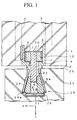
- structural member 1 As shown in FIG. 1, a connecting rod 3 projecting outward from the connecting surface 2 of structural member 1 is attached inside structural member 1, which consists of one segment.
- the end 3a of connecting rod 3 is tapered so that its diameter gradually reduces in the direction of the tip.
- Supporting plate 4 is embedded inside structural member 1 parallel to connecting surface 2. This supporting plate 4 is fixed in place by fixing member 6 which itself is fixed to structural member 1 by anchor 5. Housing case 7 is attached to the rear surface of supporting plate 4. This housing case 7 is embedded in structural member 1 and forms a housing space 8. Opening 9 is formed in supporting plate 4 opening in the forward direction of connecting surface 2.
- Base end 3b of connecting rod 3 is disposed inside housing space 8 by insertion through opening 9.
- Head portion 10 is provided to base end 3b for engaging with supporting plate 4. This head portion 10 attaches nut 11 to base end 3b of connecting rod 3.
- Head portion 10 is formed to have a larger diameter than opening 9.
- housing case 7 which forms housing space 8 has indentations 7a where the inner circumferential diameter of housing case 7 is reduced.
- the space between indentation 7a and near part 11a of nut 11 is approximately 2mm.
- a space is also present between the inner wall of housing case 7 and corner 11b of nut 11, with this dimension set so as to be approximately equal to the space between indentation 7a and near part 11a of nut 11.
- head portion 10 of connecting rod 3 is formed to have a diameter larger than opening 9. As a result, connecting rod 3 does not slip out toward the front of connecting surface 2.
- connecting rod 3 itself, which projects outward from opening 9, can move in a direction parallel to connecting surface 2 within connecting surface 2 of structural member 1.
- structural member 21 consisting of another segment which connects with structural member 1 will be explained.
- Connector 23 is provided to other structural member 21 inside connecting surface 22.
- Connector 23 has a sleeve 24 which is formed to taper in the direction opposite that indicated by Y shown in FIG. 1.
- a plurality of wedges 25 are disposed in a ring within sleeve 24 to a form an insertion fixing hole H at their center through which connecting rod 3 is inserted.
- the plurality of wedges 25 are disposed so as to be freely moveable in the longitudinal direction of sleeve 24 with their outer circumferential surfaces in contact with the inner circumferential surface of sleeve 24.
- a spring holding member (urethane case) 26 is attached at the rear of the large diameter end of sleeve 24 by means of a bent portion 24a.
- Urethane spring 27 is housed inside spring holding member 26 as a elastic member for biasing wedges 25 toward the small diameter end of sleeve 24 so that the diameter of insertion fixing hole H is reduced.
- Numeric symbol 28 indicates a retainer for partitioning wedges 25 and urethane spring 27.
- connecting rod 3 When connecting structural members 1,21, connecting rod 3 is pushed into sleeve 24 of connector 23 by moving one structural member 1 in the Y direction, causing wedges 25 to compress urethane spring 27. Wedges 25 retreat toward the bottom (in the Y direction in the figure) of sleeve 24, and the diameter of insertion fixing hole H formed by wedges 25 narrows. In this way, connecting rod 3 is inserted into this insertion fixing hole H.
- connecting rod 3 In response to a slipping out movement by connecting rod 3, the diameter of the insertion fixing hole H formed by wedges 25 becomes still smaller, thereby increasing its fixing force. As a result, connecting rod 3 is strongly connected to connector 23, so that structural members 1,21 are connected in a unitary manner.
- connection action When connecting structural members 1,21 in the example shown in FIG. 1, the axes of connecting rod 3 and connector 23 coincide with one another in the connecting action - - what might be called an "ideal connection action".
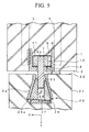
- actual connection of structural members 1,21 is not limited absolutely to a state in which the axes of connecting rod 3 and connector 23 coincide. Rather, as shown in FIG. 5, it is frequently the case that connecting rod 3 and connector 23 enter the connecting action with their axes deviating in the X direction for example, i.e., an eccentric insertion.
- the amount by which wedges 25 retreat can be increased by making the urethane spring 27 thicker on the connector 23 side.
- connection of structural members 1,21 by means of engagement between connecting rod 3 and connector 23 is possible.
- connecting rod 3 pushes wedges 25 in the X direction.
- Wedges 25 pushed by connecting rod 3 retreat greatly in the Y direction, compressing urethane spring 27 more strongly in the Y direction.
- axial deviation is permitted in the case of an eccentric insertion.
- spring holding member 26 increases as urethane spring 27 is made thicker. Accordingly, this leads to an increase in the size and cost of the connecting structure.
- connecting rod 3 is pushed in the X direction by wedges 25, so that head portion 10 inside housing space 8 moves in the X direction.
- connecting rod 3 itself also moves in the X direction.
- structural members 1,21 can be connected with a greater degree of axial deviation permitted between connecting rod 3 and connector 23.
- connecting structure for structural members 1,21 it is possible to respond to an eccentric insertion from both the connector 23 side and the connecting rod 3 side.
- connecting rod 3 it is possible to respond to an even greater degree of eccentricity.
- urethane spring 27 can be made thin, enabling a reduction in the side of connector 23.
- urethane spring 27 is held inside spring holding member 26 of connector 23 as a elastic member.
- the elastic member is not limited to urethane spring 27.
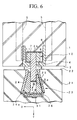
- FIG. 6 The arrangement shown in FIG. 6 employs a belleville spring 31 as the elastic member used in connector 23.
- This example also has the same effect as in the case of the connecting structure discussed above. Namely, even if a thin belleville spring 31 is employed as a elastic member, deviation of structural members 1,21 can be permitted with surety.
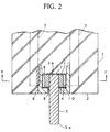
- the connecting structure according to the second embodiment differs from that of the first embodiment in the provision of a sealing member (O ring) 32 in the vicinity of connecting rod 3 of one structural member 1.
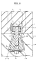
- sealing member 32 When connecting one structural member 1 and another structural member 21 in this type of connecting structure, sealing member 32 is compressed by connecting surfaces 2,22 of structural members 1,21. As shown in FIG. 8, sealing member 32 enters into sleeve 24, sealing the interval of space between the inner circumferential surface at the sleeve 24 entrance and the outer circumferential surface of connecting rod 3. As a result, intrusion of water into connector 23 is prevented.
- sealing member 32 when there is a space between connecting rod 3 and fixing member 6, sealing member 32 also seals this space. As a result, sealing member 32 also functions to prevent intrusion of water into housing case 7.
- the connecting structure in this third embodiment differs from that shown in the second embodiment in that the area of connecting rod 3 near its tip 3a has the form of a saw-blade in cross-section, as shown in the figure.
- another point of difference is the provision of a metallic plate 33 formed in a unitary manner with retainer 28 at the inner circumferential surface of wedges 25.
- connecting rod 3 at its tip 3a has this saw-blade form in cross-section, once structural members 1,21 are connected, even if there is a force working in a direction which would separate and pull apart the two members, the outer circumferential surface of connecting rod 3 with this saw-blade form in cross-section is interlocked with the inner circumferential surfaces of wedges 25. As a result, frictional force increases, so that structural members 1,21 are not easily separated. Thus, a more strongly fixed connection between structural members 1,21 is enabled.
- the inner circumferential surfaces of wedges 25 are reinforced by metallic plate 33. As a result, the strength of wedges 25 is ensured, while the inner circumferential surface thereof is protected.
- This embodiment is equivalent to the first and second embodiments with respect to there being sufficient allowance for axial deviation between connecting rod 3 and connector 23 even when belleville spring 31 is made thin.
- the area at tip 3a of connecting rod 3 is formed into a saw-blade in cross-section.
- the inner circumferential surface of wedges 25 or metallic plate 33 may be formed so as to interlock with the saw-blade form of connecting rod 3, thereby enabling an even stronger connecting force between structural members 1,21.
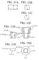
- FIGS. 11 ⁇ 13 show examples of methods for making wedges 25 of connector 23.
- These wedges 25 are formed via the steps of cutting a circular plate from a steel or other metallic round rod in a mechanical process using a milling machine or a sawing machine as shown in FIGS. 11 (a), (b), and (c); subjecting the circular plate to bonderizing; forming the circular plate into an intermediate product 25 such as shown in FIGS. 11 (d) and (e) that is flabellate in cross-section by cold forging; and disposing inside forging machine 41 a plurality (four here) of the thus-formed intermediate products 25A in a circle so that their lateral sides 25Aa face one another, and forging this plurality of intermediate products 25A simultaneously into wedges under the operation of forging machine 41.
- (C) is a view of the bottom surface of (b), (e) is a view of the bottom surface of (d), and (g) is a view of the bottom surface of (f).
- Forging machine 41 is provided with a lower dice 42, upper punch 43 and notch out pin 44, and is designed to simultaneously cold forge the plurality of intermediate products 25A (see left half of FIG. 13) which have been placed in a circle around axis 43a of upper punch 43 into wedges 25 by lowering upper punch 43 with respect to lower dice 42.
- a stamp is attached to the pressing surface 43b of upper punch 43 for stamping the end surface on the large diameter side of each wedge 25 during forge-molding with a symbol or a graphic character, such as K, (hereinafter, "symbol") showing the alignment of the plurality of wedges 25.
- the stamp may be convex or concave. Typically, however, it is convex (but concave in the case of symbol K).
- intermediate product 25A was formed by forging. Intermediate product 25A may be formed by other means, such as mechanical processing, however. The method for forming intermediate product 25A is optional. Bonderizing of intermediate product 25A is carried out as necessary.
- Forging machine 41 in FIG. 13 is designed to form tips 25a of wedges 25 into a natural form.
- Forging machine 41 is not limited thereto, however, but rather the design and type formed is optional.
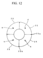
- Symbol 25b in FIG. 12 indicates cut-outs formed in the outer peripheral corners of the edge surface on the large diameter side of wedges 25.
- wedges 25 can be formed at low cost, with good accuracy of assembly for the plurality of wedges 25. Moreover, since there is no machine allowance for cutting incurred, no reduction in the width of wedges 25 nor decrease in the contact surface with sleeve 24 occurs. Accordingly, a strong fastening force can be obtained, while at the same time forming a small diameter wedge 25.
- wedges 25 having a high degree of strength can be obtained.
- a reduction in the size of the machining equipment can be anticipated. Productivity is improved and defective products become less likely. Accordingly, wedges 25 can be formed a lower cost.
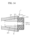
- FIG. 14 shows an example of a connector 23 employing wedges 25 formed in the above-described production method.
- Connector 23 is formed in the main of tapered sleeve 24 which is circular in cross-section; a plurality of wedges 25 which are disposed in a circle to form insertion fixing hole H of connecting rod 3 at their center, wedges 25 housed inside sleeve 24 to be freely moveable in the longitudinal direction of sleeve 24 with their outer circumferential surfaces in contact with the inner circumferential surface of sleeve 24; and cylindrical urethane spring 27 provided to the large diameter rear end of sleeve 24, biasing wedges 25 toward the small diameter tip of sleeve 24 so that the diameter of insertion fixing hole H becomes smaller.
- each wedge 25 is housed inside sleeve 24 in the same array as employed at the time of forge-molding.
- a spring holding member 26 is fixed in place by bent member 24a at the rear end
- the strength of spring holding member 26 is increased by the formation of projection 26a at the center of the bottom of spring holding member 26.
- projection 26a engages with the hole at the center of urethane spring 27 and fixes urethane spring 27 in a specific position.
- connector 23 employing wedges 25 formed by the above-described production method, not only is the accuracy of assembly of the plurality of wedges 25 excellent, but, because a machine allowance for a cutting process is not necessary, the contact area with respect to sleeve 24 is expanded by that portion. As a result, connecting rod 3 can be tightly joined, thus a strong, stable connecting force can be obtained.
- the loading number (the number of wedges 25 disposed inside sleeve 24) of intermediate products 25A in forging machine 41 is not limited to 4. Rather, a loading number of 2, 3 or, depending on the circumstances, 5 or more is possible.
- a flat spring, coil spring or the like may be used in urethane spring 27.
- connector 23 is supported by a mold-plate during production of structural member 21 having a connector 23.
- numeral 51 is a mold-plate for molding structural member 21.
- An attachment hole 52 is formed passing through mold-plate 51.
- Attaching member 53 attaches connector 23 to the area around attachment hole 52 at inner surface 54a of side plate 54 of mold-plate 51.
- the connector 23 in this example has a cylindrical sleeve 24 which has a bottom.
- a elastic member 27 is disposed to the bottom 24a of sleeve 24.
- a horizontal and vertical reinforcing arrangement 55 is disposed to the inner portion of mold-plate 51.
- An anchor 5 is weld-fixed to the outer circumference of sleeve 24 of connector 23. Anchor 5 is wrapped by reinforcing arrangement 55.
- Attaching member 53 has a cylindrical pin 57 which is inserted into and engages with insertion fixing hole H of the wedges 25 inside connector 23 by inserting through attachment hole 52 of side plate 54 of mold-plate 51. Stopping members 58 are provided to cylindrical pin 57 for stopping at the outer surface 54b of side plate 54 of mold-plate 51.
- a cylindrical elastic member 59 capable of elastic deformation is provided to the end of cylindrical pin 57 on its connector 23 side.
- Attachment bolt 60 is provided to cylindrical pin 57 passing through the internal portion thereof. The head portion 60a of attachment bolt 60 is stopped by end surface 59a of elastic member 59.
- Attachment nut 61 is provided by screw-attachment to the end portion 60b of attachment bolt 60.
- Cylindrical pin 57 is formed so as to engage with attachment hole 52 at the side plate 54 of mold-plate 51. As a result, it is simple to align attaching member 53 and connector 23.
- Stopping member 58 is a tightening nut which is screwed on to cylindrical pin 57. Namely, male screw 57a is formed to the outer circumferential surface of the end of cylindrical pin 57. Stopping member 58, which is a tightening nut, is screwed on to male screw 57a to be freely moveable along axis CT1, stopping member 58 coming into contact with the outer surface 54b of side plate 54 of mold-plate 51.
- stopping member 58 be a tightening nut. Rather, stopping member 58 may also be a circular member fixed to cylindrical pin 57, for example.
- Elastic member 59 may consist of any type of material, provided that it is capable of elastic deformation. In the discussion here, a rubber material is employed.
- Attachment nut 61 is screwed on to the end 60b of attachment bolt 60 so as to be freely moveable along the direction of axis CT1, attachment nut 61 coming into contact with end surface 57b of cylindrical pin 57.
- Attaching member 53 has the structure described above. Accordingly, as described below, the attachment and release of connector 23 to and from mold-plate 51 can be carried out easily and quickly.
- connector 23 is disposed to the area around attachment hole 52 at the inner surface 54a of side plate 54 of mold-plate 51 with its end in contact with inner surface 54a and its axis coinciding with axis CT1 of attachment hole 52.
- attaching member 53 is disposed to the area around attachment hole 52 at outer surface 54b of side plate 54 of mold-plate 51.
- Elastic body 59 and cylindrical pin 57 are inserted into connector 23 via attachment hole 52 of mold-plate 51.
- Stopping member 58 is designed to be stopped by coming into contact with outer surface 54b of side plate 54 of mold-plate 51.
- the axis of cylindrical pin 57 coincides with axis CT1.
- the axis of connector 23 into which cyclindrical pin 57 and elastic member 59 have been inserted also coincides with axis CT1 of attachment hole 52.
- alignment of connector 23 can be carried out easily.
- attachment nut 61 is fastened on the cylindrical pin 57 side.
- head portion 60a of attachment bolt 60 which has stopped end surface 59a of elastic member 59 is drawn close to the cylindrical pin 57 side.
- elastic member 59 is compressed, undergoing elastic deformation to become flatter.
- the diameter of elastic member 59 widens as a result.
- the widened elastic member 59 uniformly presses the inner circumferential surface of the plurality of wedges 25 in connector 23.
- connector 23 is fixed in place to attaching member 53 with its axis coinciding with axis CT1.
- attaching member 53 and connector 23 sandwich lateral plate 54 of mold-plate 51 therebetween, thus serving to fix mold-plate 51 as well.
- connector 23 is disposed and fixed in place within mold-plate 51.
- stopping member 58 consisting of the tightening nut is fastened on the mold-plate 51 side.
- connector 23 is drawn close to inner surface 54a of side plate 54 of mold-plate 51 and tightly affixed, thereby securing the fixing thereof.
- attaching member 53 is employed to attach connector 23 to mold-plate 51 by means of a simple operation in which cylindrical pin 57 and elastic member 59 are inserted into connector 23 via attachment hole 52 of mold-plate 51, and attachment nut 61 is tightened.
- cylindrical pin 57 and elastic member 59 are inserted into connector 23 via attachment hole 52 of mold-plate 51, and attachment nut 61 is tightened.
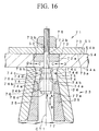
- FIG. 16 shows an example of the attachment of connector 23 to a specific position on mold-plate 51 employing another attaching member 71.
- This attaching member 71 has an engaging portion 72 which inserts into and engages with attachment hole 52 of side plate 54 of mold-plate 51.
- Engaging portion 72 is formed as a circular disk, with its circumferential wall 72a contacting attachment hole 52.
- a plate-shaped stopping member 73 is provided fixed to the outer surface 54b side of side plate 54. Surface 73a on the side plate 54 side of stopping member 73 is stopped by outer surface 54b of side plate 54.
- Passage holes 72b,73b formed centered on axis CT1 of attachment hole 52 are formed to engaging member 72 and stopping member 73, respectively.
- Connector 23 is disposed to the inner surface 54a of side plate 54 of mold-plate 51.
- a plurality of wide-diameter pieces 74 are disposed to the open end of tapered inner circumferential wall 24b of sleeve 24 of connector 23. These wide-diameter pieces 74 have respective projections 74a projecting toward the axis CT1 side.
- the surface of each wide projection 74a on the axis CT1 side forms a tapered surface 74b which gradually approaches axis CT1 as the open end of sleeve 24 is approached.
- Stopping surfaces 74c are formed to the open end side of sleeve 24 of each projection 74a. Stopping surfaces 74c are formed at right angles with respect to axis CT1.
- Mutually communicating grooves 74d are provided to the outer circumferential surface of wide-diameter pieces 74 centered on axis CT1.
- Ring-type springs 75 engage with grooves 74d in the plurality of wide-diameter pieces 74 as a biasing means for biasing these wide-diameter pieces 74 toward axis CT1.
- wide-diameter piece manipulating member 76 is disposed between the plurality of wide-diameter pieces 74.
- a tapered surface 76a is formed to the top part of wide-diameter piece manipulating member 76. This tapered surface 76a is designed to come in contact with the tapered surface 74b of wide-diameter piece 74.
- Wide-diameter piece manipulating member 76 moves toward attachment hole 52 along axis CT1, so that wide-diameter pieces 74 are moved apart from one another. Conversely, when wide-diameter piece manipulating member 76 moves along axis CT1 in the direction away from attachment hole 52, wide diameter pieces 74 come into contact with one another due to the biasing force of ring-shaped spring 75.
- Engaging portion 76b is formed in a circle projecting outward at the upper end of wide-diameter piece manipulating member 76. This engaging portion 76b engaging with engaging surfaces 74c of projections 74a of wide-diameter pieces 74 when wide-diameter pieces 74 are close together.
- Attachment bolt 77 is provided passing through the inside of wide-diameter piece manipulating member 76.
- the head portion 77a of attachment bolt 77 is stopped by the end surface 76c of wide-diameter piece manipulating member 76.
- attachment bolt 77 is inserted into passage hole 72b of engaging portion 72 and passage hole 73b of stopping member 73.
- Attachment nut 78 is screwed on to the end portion of attachment bolt 77, with attachment nut 78 coming into contact with stopping member 73.
- attaching member 71 and the like are designed as described above, the attachment and removal of connector 23 to and from mold-plate 51 can be carried out easily and quickly.
- the open end side of connector 23 is brought into contact with the inner surface 54a of side plate 54 of mold-plate 51 while being made to coincide with axis CT1 of attachment hole 52.
- attaching member 71 is disposed to the area around attachment hole 52 at outer surface 54b of side plate 54 of mold-plate 51.
- Wide-diameter piece manipulating member 76 and wide-diameter pieces 74 of attaching member 71 are inserted into connector 23 after passing through attachment hole 52 of mold-plate 51.
- wide-diameter pieces 74 are brought close together in the direction indicated by arrows C in the figure due to the biasing force of ring-shaped springs 75. For this reason, the outer diameter of wide-diameter pieces 74 is smaller than the diameter of the open end portion of inner circumferential wall 24b of sleeve 24 of connector 23.
- wide-diameter pieces 74 and wide-diameter piece manipulating member 76 can be inserted inside sleeve 24.
- stopping member 73 comes into contact with outer surface 54b of side plate 54 of mold-plate 51 and is stopped.
- engaging member 72 engages with attachment hole 52 in this case, the axis thereof coincides with axis CT1 of attachment hole 52.
- Attachment nut 78 is fastened on the stopping member 73 side. As a result, attachment bolt 77, which stops wide-diameter piece manipulating member 76, is brought close to the attachment hole 52 side, so that wide-diameter piece manipulating member 76 moves to the attachment hole 52 side.
- wide-diameter pieces 74 disposed around wide-diameter piece manipulating member 76 are in contact with tapered inner circumferential wall 24b of sleeve 24 in connector 23. Due to frictional force, wide-diameter pieces 74 are moved in a direction (i.e., the direction indicated by arrow B in the figure) which is relatively opposite the direction (i.e.. the direction indicated by arrow A in the figure) in which wide-diameter piece manipulating member 76 moves.
- tapered surface 76a of wide-diameter piece manipulating member 76 slides in the direction indicated by arrow A relative to tapered surface 74b of wide-diameter piece 74.
- wide-diameter pieces 74 are pushed apart from one another by tapered surface 76a of wide-diameter piece manipulating member 76.
- the outer diameter of wide-diameter pieces 74 becomes greater.
- wide-diameter pieces 74 By increasing the outer diameter of wide-diameter pieces 74 in this way, wide-diameter pieces 74 are more strongly pressed against inner circumferential wall 24b of sleeve 24 of connector 23. As a result, connector 23 is fixed in place by attaching member 71.
- connector 23 is also fixed to mold-plate 51.
- the axis of connector 23 can be made to coincide with the axis CT1 of attachment hole 52. As a result, alignment can be carried out conveniently and with high accuracy.
- attaching member 71 can attach connector 23 to mold-plate 51 by means of a simple operation in which the wide-diameter pieces 74 and wide-diameter piece manipulating member 76 are inserted into connector 23 by passing through attachment hole 52 of mold-plate 51 and fastening attachment nut 78.
- the attachment operation can be done more easily and quickly.
- connection between connector 23 and mold-plate 51 must be released when releasing the mold.
- the pressing force of wide-diameter piece manipulating member 76 on wide-diameter pieces 74 can be released by loosening attachment nut 78 and moving wide-diameter piece manipulating member 76 in the direction indicated by arrow B in the figure.
- attaching member 71 as described above, the formation of a structural member 21 in which a connector 23 is provided can be carried out easily and quickly.
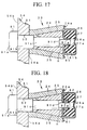
- connector 23 is supported by a mold-plate when forming a structural member 21 having a connector 23.
- a retainer 81 having a screw hole 81a is provided to connector 23 in between wedges 25 and urethane spring 27.
- screw hole 81a communicates with insertion fixing hole H formed by wedges 25.
- Screw hole 81a of retainer 81 is formed to projection 81b which engages with center hole 27a of urethane spring 27.
- urethane spring 27 housed inside spring holding member 26 may be attached to spring holding member 26 and retainer 81 by means of an adhesive agent.
- attachment bolt 91 When attaching connector 23 to mold-plate 51, attachment bolt 91 is inserted into insertion fixing hole H of connector 23 via attachment hole 52 which is formed in mold-plate 51, and screwed into screw hole 81a of retainer 81, bringing the open end of sleeve 24 into contact with the inner surface 54a of mold-plate 51.
- Attachment bolt 91 has a head portion 91a which has a diameter which is larger than that of attachment hole 52 of mold-plate 51.
- attachment bolt 91 has a neck portion 91b which is formed to have almost the same diameter as the diameter of the opening at the end of sleeve 24 and attachment hole 52 of mold-plate 51.
- An axis 91c which is narrower than neck portion 91b is formed at the tip of neck portion 91b.
- a screw portion 91d which is narrower than axis 91c and directly screws together into screw hole 81a of retainer 81 is formed to the end of axis 91c.
- neck portion 91b is tightly inserted into attaching hole 52 of mold-plate 51 and sleeve 24 of connector 23.
- connector 23 can be attached to a specific position on mold-plate 51 in a specific state.
- Attachment bolt 91 of course must be pulled out of the loose connector 23 when releasing the mold once the poured concrete has hardened.
- FIG. 18 shows another method for attaching connector 23 to mold-plate 51.
- a nut 92 in which a screw hole 92a is formed is provided to retainer 81.
- nut 92 is attached in a unitary manner to retainer 81 by means of welding or adhesion. However, it may also be disposed by engagement between retainer 81 and urethane spring 27 to prevent free rotation.
- attachment bolt 91 in this example is not limited to that described above. Rather, the shape of attachment bolt 91 may be changed in various ways in response to the structure of connector 23.
- the present invention's connecting structure enables extremely easy and sure connection of structural members, even if there is a slight positional deviation between the structural members to be connected.
Landscapes
- Engineering & Computer Science (AREA)
- Architecture (AREA)
- Structural Engineering (AREA)
- Mining & Mineral Resources (AREA)
- Civil Engineering (AREA)
- Life Sciences & Earth Sciences (AREA)
- General Life Sciences & Earth Sciences (AREA)
- Geochemistry & Mineralogy (AREA)
- Geology (AREA)
- Lining And Supports For Tunnels (AREA)
- Joining Of Building Structures In Genera (AREA)
Applications Claiming Priority (7)
| Application Number | Priority Date | Filing Date | Title |
|---|---|---|---|
| JP30682696 | 1996-11-18 | ||
| JP30682796 | 1996-11-18 | ||
| JP30682696 | 1996-11-18 | ||
| JP30682796 | 1996-11-18 | ||
| JP9020793A JPH10220184A (ja) | 1997-02-03 | 1997-02-03 | セグメントの接合構造 |
| JP2079397 | 1997-02-03 | ||
| PCT/JP1997/001473 WO1998022694A1 (fr) | 1996-11-18 | 1997-04-28 | Dispositif d'assemblage |
Publications (2)
| Publication Number | Publication Date |
|---|---|
| EP0955448A1 true EP0955448A1 (fr) | 1999-11-10 |
| EP0955448A4 EP0955448A4 (fr) | 2000-02-23 |
Family
ID=27283170
Family Applications (1)
| Application Number | Title | Priority Date | Filing Date |
|---|---|---|---|
| EP97919716A Withdrawn EP0955448A4 (fr) | 1996-11-18 | 1997-04-28 | Dispositif d'assemblage |
Country Status (5)
| Country | Link |
|---|---|
| US (1) | US6305873B1 (fr) |
| EP (1) | EP0955448A4 (fr) |
| KR (1) | KR20000053268A (fr) |
| CN (1) | CN1244901A (fr) |
| WO (1) | WO1998022694A1 (fr) |
Cited By (5)
| Publication number | Priority date | Publication date | Assignee | Title |
|---|---|---|---|---|
| GB2367873A (en) * | 2000-10-14 | 2002-04-17 | Christopher Richard Smith | Coupler device |
| EP2514919A1 (fr) * | 2011-04-19 | 2012-10-24 | Ed. Züblin AG | Béton élément connexion |
| CN103754525A (zh) * | 2014-01-10 | 2014-04-30 | 德清中盈文具用品有限公司 | 一种垃圾桶的连接件 |
| CN110360195A (zh) * | 2019-06-05 | 2019-10-22 | 联想(北京)有限公司 | 一种连接结构 |
| IT202300023139A1 (it) * | 2023-11-03 | 2025-05-03 | Maccaferri Tunneling S R L | Concio prefabbricato di un rivestimento di galleria con elementi di giunzione migliorati. |
Families Citing this family (5)
| Publication number | Priority date | Publication date | Assignee | Title |
|---|---|---|---|---|
| ITPD20100131A1 (it) * | 2010-04-28 | 2011-10-29 | Impreservice Srl | Dispositivo di fissaggio di elementi in calcestruzzo |
| US10138917B2 (en) * | 2014-05-23 | 2018-11-27 | Jon Russell Koch | Connector system for rapid assembly and disassembly of panels and other members |
| CN105484764B (zh) * | 2015-12-28 | 2018-07-17 | 上海建工集团股份有限公司 | 管片纵缝连接组件、隧道管片结构及施工方法 |
| CN111622810B (zh) * | 2019-02-27 | 2022-05-24 | 中国航发商用航空发动机有限责任公司 | 连接装置、燃气涡轮发动机、连接件以及涡轮外环 |
| CN110608051A (zh) * | 2019-09-26 | 2019-12-24 | 江苏大成轨道科技有限公司 | 一种新型的轴向连接组件 |
Family Cites Families (13)
| Publication number | Priority date | Publication date | Assignee | Title |
|---|---|---|---|---|
| US3055463A (en) * | 1960-05-19 | 1962-09-25 | Rheinstahl Gmbh Wanheim | Expandable assemblies |
| US4344267A (en) * | 1980-04-10 | 1982-08-17 | Carl Dunmon & Associates, Inc. | Apparatus for joining wall panels |
| US4830536A (en) * | 1981-08-07 | 1989-05-16 | Commercial Shearing, Inc. | Method and apparatus for tunnel lining |
| US4483645A (en) * | 1982-02-16 | 1984-11-20 | Birmingham Bolt Company | Combination expansion shell and resin secured mine roof anchor assembly |
| JP2855175B2 (ja) | 1990-04-27 | 1999-02-10 | フジミ工研株式会社 | セグメントの継手装置 |
| JPH04140399A (ja) * | 1990-09-28 | 1992-05-14 | Nippon Telegr & Teleph Corp <Ntt> | トンネル覆工用セグメント接合装置および接合工法 |
| US5393165A (en) * | 1990-10-29 | 1995-02-28 | Rowan, Jr.; Robert L. | Anchor bolt repair coupling with preloading jack and epoxy injection |
| US5226302A (en) * | 1991-04-15 | 1993-07-13 | Loctec Corporation | Six-way self-adjusting lock for use on truck storage boxes and the like |
| JP2855176B2 (ja) * | 1991-08-31 | 1999-02-10 | フジミ工研株式会社 | セグメントの継手装置 |
| US5594977A (en) * | 1993-12-30 | 1997-01-21 | Mccallion; James P. | Smooth rod-gripping apparatus |
| JP2966305B2 (ja) | 1995-01-05 | 1999-10-25 | 石川島建材工業株式会社 | ピン継手の可動取付構造 |
| JP3543022B2 (ja) * | 1995-01-31 | 2004-07-14 | 前田建設工業株式会社 | セグメントの継手装置 |
| JP2000054795A (ja) * | 1998-08-11 | 2000-02-22 | Ohbayashi Corp | セグメント |
-
1997
- 1997-04-28 KR KR1019990704247A patent/KR20000053268A/ko not_active Ceased
- 1997-04-28 CN CN97181426A patent/CN1244901A/zh active Pending
- 1997-04-28 US US09/297,551 patent/US6305873B1/en not_active Expired - Fee Related
- 1997-04-28 EP EP97919716A patent/EP0955448A4/fr not_active Withdrawn
- 1997-04-28 WO PCT/JP1997/001473 patent/WO1998022694A1/fr not_active Ceased
Non-Patent Citations (2)
| Title |
|---|
| No further relevant documents disclosed * |
| See also references of WO9822694A1 * |
Cited By (9)
| Publication number | Priority date | Publication date | Assignee | Title |
|---|---|---|---|---|
| GB2367873A (en) * | 2000-10-14 | 2002-04-17 | Christopher Richard Smith | Coupler device |
| GB2367873B (en) * | 2000-10-14 | 2003-07-30 | Christopher Richard Smith | Device for joining members |
| US6616377B1 (en) | 2000-10-14 | 2003-09-09 | Bosworth Plastics Limited | Device for joining tunnel segments |
| EP2514919A1 (fr) * | 2011-04-19 | 2012-10-24 | Ed. Züblin AG | Béton élément connexion |
| CN103754525A (zh) * | 2014-01-10 | 2014-04-30 | 德清中盈文具用品有限公司 | 一种垃圾桶的连接件 |
| CN110360195A (zh) * | 2019-06-05 | 2019-10-22 | 联想(北京)有限公司 | 一种连接结构 |
| CN110360195B (zh) * | 2019-06-05 | 2021-09-14 | 联想(北京)有限公司 | 一种连接结构 |
| IT202300023139A1 (it) * | 2023-11-03 | 2025-05-03 | Maccaferri Tunneling S R L | Concio prefabbricato di un rivestimento di galleria con elementi di giunzione migliorati. |
| WO2025094068A1 (fr) * | 2023-11-03 | 2025-05-08 | Maccaferri Tunneling S.R.L. | Segment préfabriqué pour revêtement de tunnel à éléments d'assemblage améliorés |
Also Published As
| Publication number | Publication date |
|---|---|
| KR20000053268A (ko) | 2000-08-25 |
| CN1244901A (zh) | 2000-02-16 |
| EP0955448A4 (fr) | 2000-02-23 |
| WO1998022694A1 (fr) | 1998-05-28 |
| US6305873B1 (en) | 2001-10-23 |
Similar Documents
| Publication | Publication Date | Title |
|---|---|---|
| EP0955448A1 (fr) | Dispositif d'assemblage | |
| US5025546A (en) | Method of joining pipes | |
| US5769460A (en) | Connector for tubular guide rails | |
| JPS6320139A (ja) | 金属板に金属丸棒を固着する方法及びそれに使用する金属丸棒 | |
| US4850096A (en) | Method of joining pipes | |
| US9285060B2 (en) | Pipe coupling with teethed inserts, method of securing teethed inserts, and method of coupling piping | |
| US5397231A (en) | Position assembly for use in assembling two components | |
| JP2005046912A (ja) | 金属性復原部材を有する締付け用ダイス型 | |
| JPH0432276B2 (fr) | ||
| KR102154938B1 (ko) | 조립성을 향상시킨 철근 커플러 | |
| JP3572562B2 (ja) | ワンタッチ継手およびそれを用いたコンクリートユニット | |
| KR101890678B1 (ko) | 철근이음장치 | |
| JPH048818A (ja) | リッジロック方法およびその装置およびリッジロックマフラーおよびその製造方法 | |
| JP4485678B2 (ja) | コンクリート構造物の継手具及びコンクリート構造物の接合構造 | |
| CA3232960A1 (fr) | Raccord de tuyau, element d'espacement dispose dans un raccord de tuyau, et element de separation constituant un element d'espacement | |
| JP2824408B2 (ja) | 金属部品の接合方法 | |
| JPH11311240A (ja) | コネクティングロッドの加工方法 | |
| JP3526520B2 (ja) | セグメントの連結構造 | |
| JPH03293475A (ja) | コンクリート用型枠の結合方法 | |
| JP2013217107A (ja) | セグメントの継手部構造 | |
| JP3172676B2 (ja) | コンクリート構造物の継ぎ手構造 | |
| JP3877390B2 (ja) | トンネル用セグメントの連結構造 | |
| JP2928753B2 (ja) | コンクリート構造物の連結構造 | |
| JPH09158910A (ja) | 2部材結合方法及び2部材からなる構造体 | |
| JP3142989B2 (ja) | セグメントの接合構造 |
Legal Events
| Date | Code | Title | Description |
|---|---|---|---|
| PUAI | Public reference made under article 153(3) epc to a published international application that has entered the european phase |
Free format text: ORIGINAL CODE: 0009012 |
|
| 17P | Request for examination filed |
Effective date: 19990506 |
|
| AK | Designated contracting states |
Kind code of ref document: A1 Designated state(s): DE FR GB NL |
|
| A4 | Supplementary search report drawn up and despatched |
Effective date: 20000112 |
|
| AK | Designated contracting states |
Kind code of ref document: A4 Designated state(s): DE FR GB NL |
|
| STAA | Information on the status of an ep patent application or granted ep patent |
Free format text: STATUS: THE APPLICATION HAS BEEN WITHDRAWN |
|
| 17Q | First examination report despatched |
Effective date: 20021104 |
|
| 18W | Application withdrawn |
Withdrawal date: 20021115 |