EP0955535A2 - Isothermischer Durchflussregler für Luftprobenentnehmer - Google Patents
Isothermischer Durchflussregler für Luftprobenentnehmer Download PDFInfo
- Publication number
- EP0955535A2 EP0955535A2 EP99107765A EP99107765A EP0955535A2 EP 0955535 A2 EP0955535 A2 EP 0955535A2 EP 99107765 A EP99107765 A EP 99107765A EP 99107765 A EP99107765 A EP 99107765A EP 0955535 A2 EP0955535 A2 EP 0955535A2
- Authority
- EP
- European Patent Office
- Prior art keywords
- pressure
- tube
- gas flow
- flow
- gas
- Prior art date
- Legal status (The legal status is an assumption and is not a legal conclusion. Google has not performed a legal analysis and makes no representation as to the accuracy of the status listed.)
- Granted
Links
- 230000010349 pulsation Effects 0.000 claims abstract description 35
- 238000005070 sampling Methods 0.000 claims abstract description 11
- 238000011144 upstream manufacturing Methods 0.000 claims description 20
- 238000000034 method Methods 0.000 claims description 10
- 238000013016 damping Methods 0.000 claims description 2
- 238000009530 blood pressure measurement Methods 0.000 claims 1
- 230000009977 dual effect Effects 0.000 claims 1
- 238000012886 linear function Methods 0.000 claims 1
- 238000005086 pumping Methods 0.000 abstract 1
- 230000006870 function Effects 0.000 description 7
- 238000005259 measurement Methods 0.000 description 5
- 239000002245 particle Substances 0.000 description 4
- 238000009795 derivation Methods 0.000 description 3
- 230000000694 effects Effects 0.000 description 3
- 238000004364 calculation method Methods 0.000 description 2
- 238000006243 chemical reaction Methods 0.000 description 2
- 239000000428 dust Substances 0.000 description 2
- 239000012530 fluid Substances 0.000 description 2
- 230000004044 response Effects 0.000 description 2
- 238000013459 approach Methods 0.000 description 1
- 238000010276 construction Methods 0.000 description 1
- 239000000356 contaminant Substances 0.000 description 1
- 238000013500 data storage Methods 0.000 description 1
- 238000010586 diagram Methods 0.000 description 1
- 230000003292 diminished effect Effects 0.000 description 1
- 229920001971 elastomer Polymers 0.000 description 1
- 239000000806 elastomer Substances 0.000 description 1
- 238000001595 flow curve Methods 0.000 description 1
- 230000005484 gravity Effects 0.000 description 1
- 238000005461 lubrication Methods 0.000 description 1
- 230000000737 periodic effect Effects 0.000 description 1
- 230000002040 relaxant effect Effects 0.000 description 1
Images


Classifications
-
- G—PHYSICS
- G01—MEASURING; TESTING
- G01N—INVESTIGATING OR ANALYSING MATERIALS BY DETERMINING THEIR CHEMICAL OR PHYSICAL PROPERTIES
- G01N1/00—Sampling; Preparing specimens for investigation
- G01N1/02—Devices for withdrawing samples
- G01N1/22—Devices for withdrawing samples in the gaseous state
- G01N1/2273—Atmospheric sampling
-
- G—PHYSICS
- G01—MEASURING; TESTING
- G01N—INVESTIGATING OR ANALYSING MATERIALS BY DETERMINING THEIR CHEMICAL OR PHYSICAL PROPERTIES
- G01N1/00—Sampling; Preparing specimens for investigation
- G01N1/02—Devices for withdrawing samples
- G01N1/22—Devices for withdrawing samples in the gaseous state
- G01N1/24—Suction devices
-
- G—PHYSICS
- G01—MEASURING; TESTING
- G01N—INVESTIGATING OR ANALYSING MATERIALS BY DETERMINING THEIR CHEMICAL OR PHYSICAL PROPERTIES
- G01N1/00—Sampling; Preparing specimens for investigation
- G01N1/02—Devices for withdrawing samples
- G01N1/22—Devices for withdrawing samples in the gaseous state
- G01N1/2273—Atmospheric sampling
- G01N2001/2276—Personal monitors
Definitions
- This invention relates to a method according to the preamble of claim 1, an apparatus according to the preamble of claim 9, and to a gas flow measuring device according to the preamble of claim 17.
- it relates to controlling and measuring the air flow in an air sampling device.
- it utilises the concept of isothermal airflow in a flow measuring device, and substantially eliminates the effects of pulsation in the flow of sampled air induced by the strokes of a vacuum pump.
- the volume or rate of air delivered by a small vacuum pump such as is commonly used in a personal air sampler may be controlled and/or measured by employing the known characteristics of the pump in a microprocessor or the like, and comparing the known characteristics to current inputs representing flow, perhaps modifying the inputs by other variables such as outside air pressure or temperature.
- Various prior art reflects approaches to the problem of maintaining accurate air flow readings for use in calculating the concentrations of air contaminants.
- a table of values is used which relate the pump motors RPM to air flow rates, store them in a microprocessor, and modulate the current pulse width as a function of deviations from the known RPM/flow relationship.
- Pulse width modulation is also used in US-A-5,269,659 to control the air pump, as a function of pressure differential across a Venturi.
- US-A-5,163,818, uses a programmable computer to calculate flow from a number of variables, and to regulate the voltage to the pump motor to maintain a desired air flow rate.
- US-A-5,520,517 bases the pump motor control on changes in load, sensed by changes in pressure and speed and compared to pump characteristics stored in memory.
- US-A-4,532,814 discloses: known pump sampling systems which control flow by adjustment of pump motor speed produce an air flow with relatively high pulse undulations particularly at low flow levels. With a highly pulsed flow it is difficult to set the flow rate. A steady flow of gas or air to a sample collecting device is maintained by providing a supplementary flow of gas or air to the inlet of the pump in response to a signal representing pressure differential across an orifice in the air or gas conduit, thus avoiding controls on the pump motor. Settings for the flow control valve are manually adjusted. The supplementary flow to the inlet of the pump may be taken from the outlet of the pump. See also US-A-4,576,054.
- US-A-5,562,002 discloses a device for damping the pump pulsations in a reciprocating piston flowtube comprising a diaphragm and a porous member having open channels.
- the piston drops by gravity to the bottom of the flowtube; the diaphragm is supported by the porous member.
- US-A-5,000,052 shows a laminar flow sensing element which comprises a stack of individual flow channels.
- None of the above constructions provide a simple device for measuring air or gas sample flow which neutralises the effect of the back pressure caused by the strokes.
- US-A-5,295,790 requires a special laminar flow element such as porous member in a suitable housing, which will simulate this linear relationship between the flow rate and pressure drop in a portable personal sampling pump, provided the air flow is maintained at a low Reynolds number. While trying to simulate linear relationship, this is done at the cost of providing the special laminar flow element.
- the porous element or a small orifice are susceptible to the build-up of particles from the air which can clog up the orifices through which the air must pass, and across which pressure drop is measured. It should be noted that a major use of air sampling pumps of this type is for dust measurement and even with a suitable in-line filter, small particles can still pass into the sensor causing the build-up of changes in calibration over time.
- US-A-5,621,180 uses a coiled capillary tube of 5 cm to 5000 cm length and an internal diameter up to 0.53 mm to control the flow of gas for a predetermined time into an evacuated sample vessel.
- the developed air sampling system uses a tube of large bore in relation to dust particles, such that they will pass through the system rather than clog up small air passageways.
- This invention utilises the mathematical relationship that exists between the velocity of a compressible medium (air or other gas) flowing isothermally through a smooth conduit and the pressure drop measured across the two ends of the conduit.
- the flow can be considered to be isothermal if the energy converted to heat by friction is equal to the heat transferred out of the fluid, i.e. the air maintains constant temperature.
- This condition can occur in a uninsulated conduit with the same temperature inside and out, with low fluid velocity, i.e. typically up to about three litres of air per minute but including also flows up to 30 litres per minute.
- the invention utilises a pulsation damper which is a small chamber including a diaphragm in at least one of its walls.
- the pulsation damper is inserted in the main flow conduit of the air sample exhaust, downstream of the pump.
- the diaphragm will modify the pulsations of the flow in a predictable manner which permits accurate conversion to flow rate.
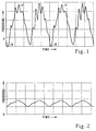
- Figure 1 illustrates a unitless profile of pressure versus time typically produced by a double diaphragm pump at the input of a flow measuring device, exemplified in this case by an isothermal sensor tube described elsewhere herein.
- Periodic negative pressures at points N are notable. Such negative pressure points represent back flow, and complicate the accurate calculation of flow. Positive peaks P tend to be sharp but cleaved.
- Figure 2 shows a plot of pressure versus time similar to that of Figure 1 where a pulsation damper is connected to the air conduit at the upstream end of an isothermal sensor according to the invention, as illustrated in Figure 3. It will be seen that no negative pulses are delivered, and the positive peaks P are benign compared to those of Figure 1. Such a flow pattern is much easier to work with, specifically to project an accurate flow rate, than the pattern of Figure 1.
- Air intake 1 for pump 2 comes from one or more sample collecting devices not shown, upstream of air intake 1; the pump 2 draws a vacuum on the sample collecting device or devices.
- Conduit 3 leads to isothermal sensor tube 8.
- a pulsation damper 9 is interposed. Pulsation damper 9 is a small chamber into which air may enter from channel 3. Pulsation damper 9 has a diaphragm 6, shown in its normal position; dotted line 5 represents the extended position of diaphragm 6 when it responds to increased pressure in the chamber of pulsation damper 9.
- pulsation damper 9 Connected to pulsation damper 9 is pressure transducer 7 for measuring pressure in pulsation damper 9, effectively the upstream end of isothermal sensor tube 8.
- the damped version of the air flow meter, comprising the pulsation damper 9, isothermal sensor tube 8, and pressure transducer 7, is shown in the dotted square 4.
- Pressure transducer 7 is conventional in that any transducer capable of sensing air pressure and converting it to an electrical signal representative thereof may be used.
- the analog or digital signal representing pressure at the upstream end of isothermal sensor tube 8 may be used to calculate flow, by itself, or using also either atmospheric pressure at end 10 of isothermal sensor tube 8 (the atmospheric pressure may be measured anywhere in the vicinity) or based on actual sensing of pressure near the end of tube 8 as shown in Figure 3c.
- Flow calculation is accomplished by a microprocessor such as microprocessor 20, shown in Figures 5a and 5b, which has stored in its memory the air flow/pressure calibration of the isothermal sensor tube 8.
- FIG. 3b is a variation which does not employ pulsation damper 9.
- Transducer 7 is connected directly to the upstream end of isothermal air tube 8.
- Electrical output from transducer 7, representing pressure at the upstream end of isothermal sensor tube 8 may be input directly to a microprocessor comparison with a pressure/flow curve stored in memory, derivation of flow, and generation of visible indications of flow, conversion of flow to volume over time, and/or generation of a control signal for the pump as a function of flow.
- These functions may be performed with or without another pressure input such as a measurement of pressure at downstream end 10 of the isothermal sensor tube 10, or a measurement of atmospheric pressure; the stored curve may take such measurements into account.
- transducer 7 operated as a differential transducer. That is, it receives pressure inputs through connection 11 to the exhaust end of isothermal sensor tube 8 and also through connection 12 to pulsation damper 9, generating an electrical signal as a function of the difference.
- the signal generated by transducer 7, whether representing the pressure in pulsation damper 9 alone, or the difference between pressure in pulsation damper 9 and atmospheric pressure, or the difference between pressure in pulsation damper 9 and measured exiting pressure of isothermal sensor tube 8, may be used to calculate the flow in a microprocessor (see Figures 5a and 5b) utilising a curve such as that of Figure 4.
- Isothermal sensor tube 8 the characteristics of an isothermal sensor tube such as isothermal sensor tube 8 are shown in terms of pressure and flow. It will be seen that the relationship of pressure and flow is not linear but can readily be used for calibration, computations, and data storage. Isothermal sensor tube 8 is, as explained above, of a large enough internal diameter to pass any and all airborne particulates which might somehow find their way past the particle collection filters or other sample collection means upstream of the pump 2 (see Figures 3a, 3b, and 3c).
- a tube of smooth bore is meant having an internal diameter of about 1 millimetre to about 5 millimetres and a length of at least about 10 mm.
- the length can be conveniently up to about 150 mm. It can also be considerably longer, i.e. 500 mm or more so long as the above described isothermal relationship is present and the tube can be calibrated to a curve such as that of Figure 4.
- the tube is straight and the internal diameter or bore is of a good consistency - that is, it will not vary more than ⁇ 5%.
- the microprocessor 20 has programmed into it the airflow versus pressure characteristics for the isothermal sensor tube 8 under various conditions of temperature and atmospheric pressure.
- the user enters the required flow rate using the keyboard 19 and the microprocessor 20 varies the voltage drive to the pump motor 13 until the expected voltage is received back from the pressure transducer 7, through analog-to-digital converter 14.
- the microprocessor 20 will then adjust its output to the pump motor 13 to maintain the required flow under all loading conditions.
- the functions of the microprocessor 20 may include variables (electrical inputs) from temperature sensor 15 and atmospheric pressure sensor 16.
- Display 18 may show flow rate, a running volume total, temperatures and pressures as desired.
- the microprocessor 20 has programmed into it the airflow versus pressure characteristics for the isothermal sensor tube 8 under various conditions of temperature and atmospheric pressure.
- the user enters the required flow rate using the keyboard 19 and the microprocessor outputs the voltage that it expects the pressure sensor to produce if the airflow is at the correct rate.
- This voltage is compared with the actual voltage produced by the transducer 7.
- the analog feedback network comprising comparator 31, drive amplifier 17, pump 2, and transducer 7 adjusts the pump motor 13 until the two inputs of the comparator 21 --the microprocessor 20 output voltage and the transducer 7 output voltage -- are equal. In this way the drive to the pump 2 is adjusted to maintain the required flow under all loading conditions.
- any of the air flow meter configurations 4 shown in Figures 3a, 3b, and/or 3c may be used in either of the layouts of Figures 5a and 5b.
- the microprocessor 20 may generate not only a signal representing flow, which may be recorded and stored for reference, but may also generate a control signal for modulating the pump motor to assure a steady flow of gas.
- one form of the invention includes apparatus and methods for measuring flow by simply measuring the upstream pressure in an isothermal sensor tube and deriving the flow from a known curve such as that of Figure 4.
- the apparatus thus comprises an isothermal sensor tube, transducer means for measuring pressure in the upstream end of said tube and generating an electrical signal representing said pressure, and means for deriving a flow rate from a stored or pre-programmed relationship of pressure to flow rate.
- the derivation may take into account variations in atmospheric pressure, and/or may utilise a pressure reading at a downstream point in the isothermal pressure tube.
- the derivation may also take into account the known-formula for deriving weight flow rate or the mass flow rate described above.
- the pulsation damper For most air sampling uses, the pulsation damper is recommended. For most uses, it comprises a chamber having a volume of about 3000 mm 3 to about 20,000 mm 3 connected to the air exhaust conduit from the pump. It will have a diaphragm or other expandable portion in its wall or top, to absorb pulsations in the air flow as the air is delivered from the pump. The pressure transducer is connected directly to the chamber defined by the pulsation damper.
Landscapes
- Health & Medical Sciences (AREA)
- Life Sciences & Earth Sciences (AREA)
- Engineering & Computer Science (AREA)
- Biomedical Technology (AREA)
- Molecular Biology (AREA)
- Physics & Mathematics (AREA)
- Chemical & Material Sciences (AREA)
- Analytical Chemistry (AREA)
- Biochemistry (AREA)
- General Health & Medical Sciences (AREA)
- General Physics & Mathematics (AREA)
- Immunology (AREA)
- Pathology (AREA)
- Sampling And Sample Adjustment (AREA)
- Measuring Volume Flow (AREA)
- Control Of Fluid Pressure (AREA)
Applications Claiming Priority (2)
| Application Number | Priority Date | Filing Date | Title |
|---|---|---|---|
| US75103 | 1998-05-08 | ||
| US09/075,103 US5892160A (en) | 1998-05-08 | 1998-05-08 | Isothermal flow controller for air sampler |
Publications (3)
| Publication Number | Publication Date |
|---|---|
| EP0955535A2 true EP0955535A2 (de) | 1999-11-10 |
| EP0955535A3 EP0955535A3 (de) | 2002-07-24 |
| EP0955535B1 EP0955535B1 (de) | 2004-01-07 |
Family
ID=22123563
Family Applications (1)
| Application Number | Title | Priority Date | Filing Date |
|---|---|---|---|
| EP99107765A Expired - Lifetime EP0955535B1 (de) | 1998-05-08 | 1999-04-19 | Isothermischer Durchflussregler für Luftprobenentnehmer |
Country Status (4)
| Country | Link |
|---|---|
| US (1) | US5892160A (de) |
| EP (1) | EP0955535B1 (de) |
| CA (1) | CA2266061C (de) |
| DE (1) | DE69914013T2 (de) |
Cited By (1)
| Publication number | Priority date | Publication date | Assignee | Title |
|---|---|---|---|---|
| US7347089B1 (en) | 2005-08-30 | 2008-03-25 | The United States Of America As Represented By The Administrator Of The National Aeronautics And Space Administration | Gas volume contents within a container, smart volume instrument |
Families Citing this family (14)
| Publication number | Priority date | Publication date | Assignee | Title |
|---|---|---|---|---|
| US6116095A (en) * | 1998-11-09 | 2000-09-12 | White Consolidated Industries, Inc. | Apparatus and method for measuring air flow from a duct system |
| DE102007027326B4 (de) * | 2007-06-14 | 2009-02-19 | Diehl Bgt Defence Gmbh & Co. Kg | Gassammelvorrichtung |
| US8459098B2 (en) * | 2009-01-20 | 2013-06-11 | The United States of America, as represented by the Secretary of the Department of Health and Human Services, Centers for Disease Control and Prevention | Universal physiologic sampling pump (PSP) capable of rapid response to breathing |
| US9329066B2 (en) | 2010-03-01 | 2016-05-03 | Provtagaren Ab | Flow regulating system and monitoring device comprising said flow regulating system for the detection of air borne analytes |
| US9492071B2 (en) | 2012-04-05 | 2016-11-15 | Stryker Corporation | In-joint sensor for a surgical fluid management pump system |
| US9289110B2 (en) | 2012-04-05 | 2016-03-22 | Stryker Corporation | Control for surgical fluid management pump system |
| US9603990B2 (en) | 2012-04-05 | 2017-03-28 | Stryker Corporation | Cassette for a surgical fluid management pump system |
| FR2991452B1 (fr) * | 2012-05-30 | 2015-01-16 | Ac Sp Etude & Rech En Hygiene Ind | Procede et dispositif de prelevement d'air pour mesure d'amiante atmospherique |
| US9651038B2 (en) | 2013-09-27 | 2017-05-16 | Met One Instruments, Inc. | Pulsation suppressing air flow system for an air sampling instrument |
| US20170106199A1 (en) | 2015-10-16 | 2017-04-20 | Brady L. WOOLFORD | Integrated pump control for dynamic control of plasma field |
| CN106680046A (zh) * | 2017-01-13 | 2017-05-17 | 北京市农林科学院 | 一种有机肥堆肥气体检测装置 |
| US10539542B2 (en) * | 2017-07-26 | 2020-01-21 | Honeywell International Inc. | Pressure transient normalization within a gas detector |
| US12517017B1 (en) * | 2020-08-09 | 2026-01-06 | Nicholas Aflitto | Air sampler |
| EP4209771A1 (de) | 2022-01-07 | 2023-07-12 | InfraServ GmbH & Co. Höchst KG | Vorrichtung zur probennahme in der luft, verwendung und verfahren |
Citations (13)
| Publication number | Priority date | Publication date | Assignee | Title |
|---|---|---|---|---|
| US4269059A (en) | 1979-03-19 | 1981-05-26 | E. I. Du Pont De Nemours And Company | Dosimeter having constant flow pump |
| US4527953A (en) | 1984-10-12 | 1985-07-09 | E. I. Du Pont De Nemours And Company | Pump unit for sampling air |
| US4532814A (en) | 1983-07-12 | 1985-08-06 | Lalin Hill S | Fluid sampler and gas flow control system and method |
| US4569235A (en) | 1984-04-25 | 1986-02-11 | The United States Of America As Represented By The Secretary Of The Air Force | Portable, sequential air sampler |
| US4576054A (en) | 1983-07-12 | 1986-03-18 | Lalin Hill S | Dual mode gas sampler and pneumatic flow control system |
| US5000052A (en) | 1989-05-17 | 1991-03-19 | Sipin Anatole J | Controlled sampler |
| US5107713A (en) | 1990-03-16 | 1992-04-28 | A.P. Buck, Inc. | Air sampling pump |
| US5163818A (en) | 1990-02-05 | 1992-11-17 | Ametek, Inc. | Automatic constant air flow rate pump unit for sampling air |
| US5269659A (en) | 1992-08-28 | 1993-12-14 | University Corporation For Atmospheric Research | Air sampling pump system |
| US5295790A (en) | 1992-12-21 | 1994-03-22 | Mine Safety Appliances Company | Flow-controlled sampling pump apparatus |
| US5520517A (en) | 1993-06-01 | 1996-05-28 | Sipin; Anatole J. | Motor control system for a constant flow vacuum pump |
| US5562002A (en) | 1995-02-03 | 1996-10-08 | Sensidyne Inc. | Positive displacement piston flow meter with damping assembly |
| US5621180A (en) | 1995-05-11 | 1997-04-15 | Martinex R & D Inc. | Capillary sampling flow controller |
Family Cites Families (2)
| Publication number | Priority date | Publication date | Assignee | Title |
|---|---|---|---|---|
| US5325861A (en) * | 1989-04-12 | 1994-07-05 | Puritan-Bennett Corporation | Method and apparatus for measuring a parameter of a gas in isolation from gas pressure fluctuations |
| US5365795A (en) * | 1993-05-20 | 1994-11-22 | Brower Jr William B | Improved method for determining flow rates in venturis, orifices and flow nozzles involving total pressure and static pressure measurements |
-
1998
- 1998-05-08 US US09/075,103 patent/US5892160A/en not_active Expired - Fee Related
-
1999
- 1999-04-06 CA CA002266061A patent/CA2266061C/en not_active Expired - Fee Related
- 1999-04-19 DE DE69914013T patent/DE69914013T2/de not_active Expired - Lifetime
- 1999-04-19 EP EP99107765A patent/EP0955535B1/de not_active Expired - Lifetime
Patent Citations (13)
| Publication number | Priority date | Publication date | Assignee | Title |
|---|---|---|---|---|
| US4269059A (en) | 1979-03-19 | 1981-05-26 | E. I. Du Pont De Nemours And Company | Dosimeter having constant flow pump |
| US4532814A (en) | 1983-07-12 | 1985-08-06 | Lalin Hill S | Fluid sampler and gas flow control system and method |
| US4576054A (en) | 1983-07-12 | 1986-03-18 | Lalin Hill S | Dual mode gas sampler and pneumatic flow control system |
| US4569235A (en) | 1984-04-25 | 1986-02-11 | The United States Of America As Represented By The Secretary Of The Air Force | Portable, sequential air sampler |
| US4527953A (en) | 1984-10-12 | 1985-07-09 | E. I. Du Pont De Nemours And Company | Pump unit for sampling air |
| US5000052A (en) | 1989-05-17 | 1991-03-19 | Sipin Anatole J | Controlled sampler |
| US5163818A (en) | 1990-02-05 | 1992-11-17 | Ametek, Inc. | Automatic constant air flow rate pump unit for sampling air |
| US5107713A (en) | 1990-03-16 | 1992-04-28 | A.P. Buck, Inc. | Air sampling pump |
| US5269659A (en) | 1992-08-28 | 1993-12-14 | University Corporation For Atmospheric Research | Air sampling pump system |
| US5295790A (en) | 1992-12-21 | 1994-03-22 | Mine Safety Appliances Company | Flow-controlled sampling pump apparatus |
| US5520517A (en) | 1993-06-01 | 1996-05-28 | Sipin; Anatole J. | Motor control system for a constant flow vacuum pump |
| US5562002A (en) | 1995-02-03 | 1996-10-08 | Sensidyne Inc. | Positive displacement piston flow meter with damping assembly |
| US5621180A (en) | 1995-05-11 | 1997-04-15 | Martinex R & D Inc. | Capillary sampling flow controller |
Non-Patent Citations (1)
| Title |
|---|
| "Instruments & Control Systems", vol. 35, April 1962, article "New Laminar Flowmeter", pages: 98 - 100 |
Cited By (1)
| Publication number | Priority date | Publication date | Assignee | Title |
|---|---|---|---|---|
| US7347089B1 (en) | 2005-08-30 | 2008-03-25 | The United States Of America As Represented By The Administrator Of The National Aeronautics And Space Administration | Gas volume contents within a container, smart volume instrument |
Also Published As
| Publication number | Publication date |
|---|---|
| DE69914013T2 (de) | 2004-06-09 |
| DE69914013D1 (de) | 2004-02-12 |
| US5892160A (en) | 1999-04-06 |
| CA2266061A1 (en) | 1999-11-08 |
| EP0955535A3 (de) | 2002-07-24 |
| CA2266061C (en) | 2001-10-16 |
| EP0955535B1 (de) | 2004-01-07 |
Similar Documents
| Publication | Publication Date | Title |
|---|---|---|
| EP0955535A2 (de) | Isothermischer Durchflussregler für Luftprobenentnehmer | |
| US5520517A (en) | Motor control system for a constant flow vacuum pump | |
| US5861546A (en) | Intelligent gas flow measurement and leak detection apparatus | |
| US7185528B2 (en) | Speed and fluid flow controller | |
| US6715339B2 (en) | Self-normalizing flow sensor and method for the same | |
| CA2497630C (en) | Air sampler with integrated airflow sensing | |
| US5349852A (en) | Pump controller using acoustic spectral analysis | |
| US5295790A (en) | Flow-controlled sampling pump apparatus | |
| US5575310A (en) | Flow control system with volume-measuring system using a resonatable mass | |
| US5269659A (en) | Air sampling pump system | |
| US6564825B2 (en) | Mass flow meter systems and methods | |
| JP3022931B2 (ja) | 気体マス・フロー測定システム | |
| WO1992008957A1 (en) | Pump controller using acoustic spectral analysis | |
| EP1817554A1 (de) | Verfahren und vorrichtung zur bestimmung des strömungsdrucks unter verwendung von dichteinformationen | |
| EP0591639A2 (de) | Gasdichtemesser | |
| KR20200115555A (ko) | 절대압 및 차압 변환기를 지닌 질량 유량 제어기 | |
| US5537860A (en) | Fluid sensor including substantially linear flow resistor | |
| US20030031572A1 (en) | Personal air sampling system and pump for use therein | |
| US4644781A (en) | Fluid property measuring device | |
| Johnston et al. | Compressible flow hot-wire calibration | |
| US7127954B2 (en) | Method and device for measuring the flow rate of a fluid | |
| RU2175436C2 (ru) | Струйный автогенераторный расходомер-счетчик | |
| SU1747965A1 (ru) | Устройство дл измерени динамического давлени воздуха в вентил ционном канале | |
| JP3146603B2 (ja) | フルイディックメーター制御装置 | |
| Smith | Study of transition phenomena in a straight channel with 40 to 1 aspect ration with and without imposed pulsations Part two: Reynolds number surveys |
Legal Events
| Date | Code | Title | Description |
|---|---|---|---|
| PUAI | Public reference made under article 153(3) epc to a published international application that has entered the european phase |
Free format text: ORIGINAL CODE: 0009012 |
|
| AK | Designated contracting states |
Kind code of ref document: A2 Designated state(s): AT BE CH CY DE DK ES FI FR GB GR IE IT LI LU MC NL PT SE |
|
| AX | Request for extension of the european patent |
Free format text: AL;LT;LV;MK;RO;SI |
|
| PUAL | Search report despatched |
Free format text: ORIGINAL CODE: 0009013 |
|
| AK | Designated contracting states |
Kind code of ref document: A3 Designated state(s): AT BE CH CY DE DK ES FI FR GB GR IE IT LI LU MC NL PT SE |
|
| AX | Request for extension of the european patent |
Free format text: AL;LT;LV;MK;RO;SI |
|
| 17P | Request for examination filed |
Effective date: 20020715 |
|
| 17Q | First examination report despatched |
Effective date: 20021016 |
|
| AKX | Designation fees paid |
Designated state(s): DE FR GB IT |
|
| GRAH | Despatch of communication of intention to grant a patent |
Free format text: ORIGINAL CODE: EPIDOS IGRA |
|
| GRAS | Grant fee paid |
Free format text: ORIGINAL CODE: EPIDOSNIGR3 |
|
| GRAA | (expected) grant |
Free format text: ORIGINAL CODE: 0009210 |
|
| AK | Designated contracting states |
Kind code of ref document: B1 Designated state(s): DE FR GB IT |
|
| REG | Reference to a national code |
Ref country code: GB Ref legal event code: FG4D |
|
| REG | Reference to a national code |
Ref country code: IE Ref legal event code: FG4D |
|
| REF | Corresponds to: |
Ref document number: 69914013 Country of ref document: DE Date of ref document: 20040212 Kind code of ref document: P |
|
| ET | Fr: translation filed | ||
| PLBE | No opposition filed within time limit |
Free format text: ORIGINAL CODE: 0009261 |
|
| STAA | Information on the status of an ep patent application or granted ep patent |
Free format text: STATUS: NO OPPOSITION FILED WITHIN TIME LIMIT |
|
| 26N | No opposition filed |
Effective date: 20041008 |
|
| REG | Reference to a national code |
Ref country code: IE Ref legal event code: MM4A |
|
| PGFP | Annual fee paid to national office [announced via postgrant information from national office to epo] |
Ref country code: DE Payment date: 20110225 Year of fee payment: 13 Ref country code: FR Payment date: 20110503 Year of fee payment: 13 |
|
| PGFP | Annual fee paid to national office [announced via postgrant information from national office to epo] |
Ref country code: GB Payment date: 20110421 Year of fee payment: 13 |
|
| PGFP | Annual fee paid to national office [announced via postgrant information from national office to epo] |
Ref country code: IT Payment date: 20110420 Year of fee payment: 13 |
|
| GBPC | Gb: european patent ceased through non-payment of renewal fee |
Effective date: 20120419 |
|
| REG | Reference to a national code |
Ref country code: FR Ref legal event code: ST Effective date: 20121228 |
|
| PG25 | Lapsed in a contracting state [announced via postgrant information from national office to epo] |
Ref country code: GB Free format text: LAPSE BECAUSE OF NON-PAYMENT OF DUE FEES Effective date: 20120419 |
|
| REG | Reference to a national code |
Ref country code: DE Ref legal event code: R119 Ref document number: 69914013 Country of ref document: DE Effective date: 20121101 |
|
| PG25 | Lapsed in a contracting state [announced via postgrant information from national office to epo] |
Ref country code: FR Free format text: LAPSE BECAUSE OF NON-PAYMENT OF DUE FEES Effective date: 20120430 Ref country code: IT Free format text: LAPSE BECAUSE OF NON-PAYMENT OF DUE FEES Effective date: 20120419 |
|
| PG25 | Lapsed in a contracting state [announced via postgrant information from national office to epo] |
Ref country code: DE Free format text: LAPSE BECAUSE OF NON-PAYMENT OF DUE FEES Effective date: 20121101 |