EP0955707A2 - Lasersystem - Google Patents
Lasersystem Download PDFInfo
- Publication number
- EP0955707A2 EP0955707A2 EP99108879A EP99108879A EP0955707A2 EP 0955707 A2 EP0955707 A2 EP 0955707A2 EP 99108879 A EP99108879 A EP 99108879A EP 99108879 A EP99108879 A EP 99108879A EP 0955707 A2 EP0955707 A2 EP 0955707A2
- Authority
- EP
- European Patent Office
- Prior art keywords
- laser beam
- laser
- fourier transform
- mirror
- optical system
- Prior art date
- Legal status (The legal status is an assumption and is not a legal conclusion. Google has not performed a legal analysis and makes no representation as to the accuracy of the status listed.)
- Granted
Links
Images




Classifications
-
- G—PHYSICS
- G02—OPTICS
- G02B—OPTICAL ELEMENTS, SYSTEMS OR APPARATUS
- G02B27/00—Optical systems or apparatus not provided for by any of the groups G02B1/00 - G02B26/00, G02B30/00
- G02B27/09—Beam shaping, e.g. changing the cross-sectional area, not otherwise provided for
- G02B27/0938—Using specific optical elements
- G02B27/095—Refractive optical elements
- G02B27/0972—Prisms
-
- G—PHYSICS
- G02—OPTICS
- G02B—OPTICAL ELEMENTS, SYSTEMS OR APPARATUS
- G02B19/00—Condensers, e.g. light collectors or similar non-imaging optics
- G02B19/0004—Condensers, e.g. light collectors or similar non-imaging optics characterised by the optical means employed
- G02B19/0009—Condensers, e.g. light collectors or similar non-imaging optics characterised by the optical means employed having refractive surfaces only
- G02B19/0014—Condensers, e.g. light collectors or similar non-imaging optics characterised by the optical means employed having refractive surfaces only at least one surface having optical power
-
- G—PHYSICS
- G02—OPTICS
- G02B—OPTICAL ELEMENTS, SYSTEMS OR APPARATUS
- G02B19/00—Condensers, e.g. light collectors or similar non-imaging optics
- G02B19/0033—Condensers, e.g. light collectors or similar non-imaging optics characterised by the use
- G02B19/0047—Condensers, e.g. light collectors or similar non-imaging optics characterised by the use for use with a light source
- G02B19/0052—Condensers, e.g. light collectors or similar non-imaging optics characterised by the use for use with a light source the light source comprising a laser diode
-
- H—ELECTRICITY
- H01—ELECTRIC ELEMENTS
- H01S—DEVICES USING THE PROCESS OF LIGHT AMPLIFICATION BY STIMULATED EMISSION OF RADIATION [LASER] TO AMPLIFY OR GENERATE LIGHT; DEVICES USING STIMULATED EMISSION OF ELECTROMAGNETIC RADIATION IN WAVE RANGES OTHER THAN OPTICAL
- H01S5/00—Semiconductor lasers
- H01S5/10—Construction or shape of the optical resonator, e.g. extended or external cavity, coupled cavities, bent-guide, varying width, thickness or composition of the active region
- H01S5/14—External cavity lasers
-
- H—ELECTRICITY
- H01—ELECTRIC ELEMENTS
- H01S—DEVICES USING THE PROCESS OF LIGHT AMPLIFICATION BY STIMULATED EMISSION OF RADIATION [LASER] TO AMPLIFY OR GENERATE LIGHT; DEVICES USING STIMULATED EMISSION OF ELECTROMAGNETIC RADIATION IN WAVE RANGES OTHER THAN OPTICAL
- H01S2301/00—Functional characteristics
- H01S2301/14—Semiconductor lasers with special structural design for lasing in a specific polarisation mode
-
- H—ELECTRICITY
- H01—ELECTRIC ELEMENTS
- H01S—DEVICES USING THE PROCESS OF LIGHT AMPLIFICATION BY STIMULATED EMISSION OF RADIATION [LASER] TO AMPLIFY OR GENERATE LIGHT; DEVICES USING STIMULATED EMISSION OF ELECTROMAGNETIC RADIATION IN WAVE RANGES OTHER THAN OPTICAL
- H01S5/00—Semiconductor lasers
- H01S5/005—Optical components external to the laser cavity, specially adapted therefor, e.g. for homogenisation or merging of the beams or for manipulating laser pulses, e.g. pulse shaping
-
- H—ELECTRICITY
- H01—ELECTRIC ELEMENTS
- H01S—DEVICES USING THE PROCESS OF LIGHT AMPLIFICATION BY STIMULATED EMISSION OF RADIATION [LASER] TO AMPLIFY OR GENERATE LIGHT; DEVICES USING STIMULATED EMISSION OF ELECTROMAGNETIC RADIATION IN WAVE RANGES OTHER THAN OPTICAL
- H01S5/00—Semiconductor lasers
- H01S5/02—Structural details or components not essential to laser action
- H01S5/028—Coatings ; Treatment of the laser facets, e.g. etching, passivation layers or reflecting layers
-
- H—ELECTRICITY
- H01—ELECTRIC ELEMENTS
- H01S—DEVICES USING THE PROCESS OF LIGHT AMPLIFICATION BY STIMULATED EMISSION OF RADIATION [LASER] TO AMPLIFY OR GENERATE LIGHT; DEVICES USING STIMULATED EMISSION OF ELECTROMAGNETIC RADIATION IN WAVE RANGES OTHER THAN OPTICAL
- H01S5/00—Semiconductor lasers
- H01S5/06—Arrangements for controlling the laser output parameters, e.g. by operating on the active medium
- H01S5/065—Mode locking; Mode suppression; Mode selection ; Self pulsating
- H01S5/0651—Mode control
- H01S5/0653—Mode suppression, e.g. specific multimode
- H01S5/0655—Single transverse or lateral mode emission
-
- H—ELECTRICITY
- H01—ELECTRIC ELEMENTS
- H01S—DEVICES USING THE PROCESS OF LIGHT AMPLIFICATION BY STIMULATED EMISSION OF RADIATION [LASER] TO AMPLIFY OR GENERATE LIGHT; DEVICES USING STIMULATED EMISSION OF ELECTROMAGNETIC RADIATION IN WAVE RANGES OTHER THAN OPTICAL
- H01S5/00—Semiconductor lasers
- H01S5/20—Structure or shape of the semiconductor body to guide the optical wave ; Confining structures perpendicular to the optical axis, e.g. index or gain guiding, stripe geometry, broad area lasers, gain tailoring, transverse or lateral reflectors, special cladding structures, MQW barrier reflection layers
-
- H—ELECTRICITY
- H01—ELECTRIC ELEMENTS
- H01S—DEVICES USING THE PROCESS OF LIGHT AMPLIFICATION BY STIMULATED EMISSION OF RADIATION [LASER] TO AMPLIFY OR GENERATE LIGHT; DEVICES USING STIMULATED EMISSION OF ELECTROMAGNETIC RADIATION IN WAVE RANGES OTHER THAN OPTICAL
- H01S5/00—Semiconductor lasers
- H01S5/20—Structure or shape of the semiconductor body to guide the optical wave ; Confining structures perpendicular to the optical axis, e.g. index or gain guiding, stripe geometry, broad area lasers, gain tailoring, transverse or lateral reflectors, special cladding structures, MQW barrier reflection layers
- H01S5/2036—Broad area lasers
Definitions
- This invention relates to a laser system such as a broad area semiconductor laser, a phase-locked semiconductor laser or an optical waveguide type laser which uses a light amplifier medium having a transverse mode control mechanism comprising an optical waveguide layer which controls the transverse mode in one direction, and more particularly to a laser system in which oscillation in only a fundamental transverse mode is efficiently obtained.
- Lasers have been employed as a light source for a scanner in various fields such as a scanner for recording information on a recording medium or reading information recorded on a recording medium, and there is a demand for a higher output laser.
- the active area or the oscillation mode volume of the light amplifier medium is increased.
- the area in the transverse direction of the light amplifier medium may be increased or gain of the light amplifier medium may be increased.
- the resonator is not provided with modal discrimination function to cause oscillation in a single transverse mode, a plurality of high order transverse modes are simultaneously generated and accordingly the emitted laser beam cannot be condensed to a diffraction limit and a beam spot of high power density cannot be obtained.
- the primary object of the present invention is to provide a laser system which can oscillate only a fundamental transverse mode, thereby radiating a high quality laser beam at high output power.
- a laser system comprising
- Each of the first and second resonator mirror systems may be provided separately from the light amplifier medium or may comprise the light outlet end face of the light amplifier medium which is arranged to function as a mirror.
- the reflecting optical system comprises an inverting mirror optical system which reflects the laser beam collimated by the collimator optical system with its amplitude distribution inverted substantially by 180° about an axis which is substantially at 90° to the optical axis of the laser beam and at 45° to a normal of the optical waveguide layer.
- the inverting mirror optical system comprises
- the inverting mirror optical system comprises
- the inverting mirror optical system comprises a cylindrical lens having power in the direction substantially at 45° to a normal of the optical waveguide layer, and a mirror disposed near the focal point of the cylindrical lens.
- the inverting mirror optical system may further comprise a Fourier transform lens which subjects the laser beam collimated by the collimator optical system to Fourier transform.
- the reflecting optical system comprises an optical system which reflects the laser beam collimated by the collimator optical system with its amplitude distribution inverted substantially by 90° about the optical axis of the laser beam.
- the laser beam entering the resonator mirror optical system is reflected by the optical system to enter the light amplifier medium with its amplitude distribution in the direction substantially perpendicular to the optical waveguide layer converted to an amplitude distribution in the direction substantially parallel to the optical waveguide layer.
- the laser beam having an amplitude distribution controlled to a fundamental transverse mode in the direction substantially perpendicular to the optical waveguide layer when radiated from the light amplifier medium comes to have an amplitude distribution controlled to a fundamental transverse mode in the direction substantially parallel to the optical waveguide layer when it is reflected by the resonator mirror optical system to enter the light amplifier medium.
- the amplitude distribution in one direction in the laser beam radiated from the light amplifier medium is forced to be in the fundamental transverse mode when the laser beam is reflected by the resonator mirror optical system, and accordingly, amplification and oscillation of high order transverse modes are prevented, whereby only the fundamental transverse mode is amplified and caused to oscillate.
- a laser beam including only the fundamental transverse mode can be effectively oscillated and a high quality laser beam can be obtained at a high output power, whereby the radiated laser beam can be condensed to the diffraction limit, and a high power density can be obtained.
- a laser system 100 in accordance with a first embodiment of the present invention comprises a broad-area semiconductor laser 1 as a light source, a cylindrical lens 2 disposed near a right side light outlet end face 1A of the semiconductor laser 1, a ⁇ /2 plate 3 which rotates the direction of polarization of a laser beam Bo passing through the cylindrical lens 2, a Fourier transform lens 4 which prevents divergence of the laser beam Bo passing through the ⁇ /2 plate 3, and a right-angle prism mirror 5 which reflects at a predetermined reflectance the laser beam Bo passing through the Fourier transform lens 4 while rotating amplitude distribution of the reflected laser beam B1 by 180° about an axis which is at 90° to an optical axis X and at 45° to a normal of an active layer 7 (to be described later).
- the cylindrical lens 2 forms the aforesaid collimator optical system
- the ⁇ /2 plate 3, the Fourier transform lens 4 and the right-angle prism mirror 5 form a resonator mirror optical system 6.
- the right side light outlet end face 1A of the broad-area semiconductor laser 1 is provided with AR (antireflection) coating and the left side light outlet end face 1B is provided with a LR (low reflection coating) which is several % in reflectance.
- the active layer (optical waveguide layer) 7 of the broad-area semiconductor laser 1 is wider in the horizontal direction (in the vertical direction as seen in Figure 1A).
- the direction in which the active layer 7 is wider is taken as the direction parallel to the active layer 7 and the direction in which the active layer 7 is narrow, that is, the vertical direction as seen in Figure 1B, is taken as the direction perpendicular to the active layer 7.
- the laser beam Bo is radiated by controlling the transverse mode in the direction perpendicular to the active layer 7 to a fundamental mode by the active layer 7.
- the components in the direction parallel to the active layer 7 form parallel light and the components in the direction perpendicular to the active layer 7 form divergent light.
- the broad-area laser 1 has amplitude distribution symmetrical about the optical axis X in both the directions parallel to the active layer 7 and perpendicular to the active layer.
- the cylindrical lens 2 has power only in the direction perpendicular to the active layer 7, and as shown in Figure 1B, only the components of the laser beam Bo as radiated from the broad-area semiconductor laser 1 which are perpendicular to the active layer 7 are collimated by the cylindrical lens 2.
- the focal length of the cylindrical lens 2 is set so that the beam diameters as measured in the direction perpendicular to the active layer 7 and in the direction parallel to the active layer 7 at the back focal plane of the cylindrical lens 2 (a-plane) are substantially equal to each other. Accordingly at the a-plane, the laser beam Bo is substantially square in shape.
- the beam diameter as measured in the direction parallel to the active layer 7 is a value when the laser beam oscillates in the fundamental transverse mode in the direction parallel to the active layer 7 and which of the focal planes is back or front is determined on the basis of the direction of travel of the laser beam Bo.
- the Fourier transform lens 4 is disposed so that its front focal plane coincides with the a-plane.
- the Fourier transform lens 4 prevents the laser beam Bo from diverging.
- the right-angle prism mirror 5 is disposed so that its reflecting surface 5A coincides with the back focal plane of the Fourier transform lens 4 (b-plane) and its edge 5B is at 45° to the direction parallel to the active layer 7 in a plane perpendicular to the optical axis X as shown in Figure 1c. Accordingly, the amplitude distribution of the laser beam Bo reflected by the reflecting surface 5A of the right-angle prism mirror 5 is inverted by 180° about the edge 5B. That is, the amplitude distributions in the directions parallel and perpendicular to the active layer 7 in the laser beam Bo respectively correspond to those in the directions perpendicular and parallel to the active layer 7 in the reflected laser beam B1.
- the ⁇ /2 plate 3 is disposed so that its principal axis 3A is at 22.5° to the direction parallel to the active layer 7 and makes the direction of polarization of the laser beam Bo as radiated from the broad-area semiconductor laser 1 equal to that of the laser beam B1 reflected by the right-angle prism mirror 5 to impinge upon the broad-area semiconductor laser 1. That is, though the direction of polarization of the laser beam Bo as radiated from the semiconductor laser 1 is parallel to the active layer 7, the direction of polarization of the laser beam Bo is rotated by 45° (22.5° x2) when the laser beam Bo passes through the ⁇ /2 plate 3 and becomes perpendicular to the edge 5B of the right-angle prism mirror 5 as shown by the broken line in Figure 1C.
- the direction of polarization of the laser beam B1 reflected by the prism mirror 5 is equal to that of the laser beam Bo entering the prism mirror 5.
- the ⁇ /2 plate 3 is a reversible element, the direction of polarization of the laser beam B1 is rotated to be parallel to the active layer 7 when the laser beam B1 passes through the ⁇ /2 plate 3. Accordingly, the direction of polarization of the laser beam Bo radiated from the broad-area semiconductor laser 1 and that of the laser beam B1 entering the semiconductor laser 1 are both parallel to the active layer 7.
- the laser beam Bo radiated from the AR-coated light outlet end face 1A of the broad-area semiconductor laser 1 is controlled so that the amplitude distribution in the direction perpendicular to the active layer is in the fundamental transverse mode. Further the laser beam Bo is parallel light in the direction parallel to the active layer 7 and is divergent light in the direction perpendicular to the active layer 7. The laser beam Bo is collimated only in the direction perpendicular to the active layer 7 by the cylindrical lens 2. Accordingly, the beam diameters as measured in the directions parallel and perpendicular to the active layer 7 become equal to each other at the back focal plane of the cylindrical lens 2 (the a-plane).
- the laser beam Bo enters the right-angle prism mirror 5 without loss of light.
- the laser beam Bo which enters the right-angle prism mirror 5 is reflected by the reflecting surface 5A of the prism mirror 5.
- the edge 5B of the prism mirror 5 is at 45° to the direction parallel to the active layer 7, and accordingly, the amplitude distribution of the laser beam Bo reflected by the reflecting surface 5A of the right-angle prism mirror 5 is inverted by 180° about the edge 5B. That is, the amplitude distribution in the laser beam B1 is inverted by 180° about the edge 5B relative to the amplitude distribution in the laser beam Bo. Further the direction of polarization of the reflected laser beam B1 is equal to that of the laser beam Bo before reflection as described above.
- the laser beam B1 reflected by the right-angle prism mirror 5 reenters the Fourier transform lens 4 and is subjected to inverse Fourier transform, whereby the amplitude distribution of the laser beam Bo at the a-plane is imaged again on the a-plane by the Fourier transform lens 4 and the right-angle prism mirror 5.
- the amplitude distribution of the laser beam B1 at the a-plane is inverted by 180° about the edge 5B relative to the amplitude distribution of the laser beam Bo.
- the direction of polarization of the laser beam B1 is parallel to the active layer 7 as described above. Accordingly the laser beam Bo radiated from the semiconductor laser 1 and the laser beam B1 entering the semiconductor laser 1 are equal to each other in the direction of polarization.
- the laser beam B1 is caused to form an image on the light outlet end face 1A of the semiconductor laser 1 by the cylindrical lens 2.
- the amplitude distribution of the laser beam B1 is rotated about the edge 5B of the right-angle prism mirror 5 by 180° relative to that of the laser beam Bo, the amplitude distribution controlled to the fundamental transverse mode by the active layer 7 has been made to be an amplitude distribution in the direction parallel to the active layer 7.
- the amplitude distribution controlled to the fundamental transverse mode by the active layer 7 in the laser beam Bo radiated from the light outlet end face 1A is an amplitude distribution in the direction perpendicular to the active layer 7
- the amplitude distribution in the fundamental transverse mode in the laser beam B1 impinging upon the end face 1A is in the direction parallel to the active layer 7.
- the beam diameter of the laser beam B1 is unchanged before and after the laser beam B1 passing through the Fourier transform lens 4, the laser beam B1 impinging upon the end face 1A of the semiconductor laser 1 is effectively caused to form an image on the active layer 7.
- the amplitude distribution in the direction parallel to the active layer 7 in the laser beam Bo radiated from the semiconductor laser 1 is forced to be in the fundamental transverse mode when the laser beam Bo is reflected by the resonator mirror optical system 6, and accordingly, amplification and oscillation of high order transverse modes are prevented, whereby only the fundamental transverse mode is amplified and caused to oscillate.
- the amplitude distribution in the direction parallel to the active layer 7 includes only high order space frequency components.
- the amplitude distribution is rotated by 180° about the edge 5B of the right-angle prism mirror 5 by the resonator mirror optical system 6 and is further subjected to Fourier transform substantially in the direction perpendicular to the active layer 7 by the cylindrical lens 2, the laser beam B1 entering the active layer 7 has an amplitude distribution which is sufficiently wider than the thickness of the active layer 7 in the direction perpendicular to the active layer 7. Accordingly, in the case of the high order transverse modes, loss when the laser beam B1 is introduced into the active layer 7 becomes very large.
- the laser beam B1 entering the active layer 7 has an amplitude distribution which is substantially equal to the thickness of the active layer 7 in the direction perpendicular to the active layer 7, and is introduced into the active layer 7 substantially without loss. Accordingly, the high order transverse modes are less apt to oscillate and the fundamental transverse mode is more apt to oscillate.
- a laser beam including only the fundamental transverse mode can be effectively oscillated and a high quality laser beam can be obtained at a high output power, whereby the radiated laser beam can be condensed to the diffraction limit, and a high power density can be obtained.
- the Fourier transform lens 4 is employed, the Fourier transform lens 4 may be omitted as in a second embodiment of the present invention shown in Figures 2A to 2C.
- a laser system 100 in accordance with the third embodiment of the present invention comprises a broad-area semiconductor laser 1 as a light source, a collimator lens 30 disposed near the right side light outlet end face 1A of the semiconductor laser 1, a slit 31 which is disposed on a focal point of the collimator lens 30 and cuts the high order components parallel to the active layer 7 in the laser beam Bo collimated by the collimator lens 30, a cylindrical lens 32, a ⁇ /2 plate 3 which rotates the direction of polarization of the laser beam Bo passing through the cylindrical lens 32, and a right-angle prism mirror 5 which is the same as that employed in the first embodiment.
- the collimator lens 30, the slit 31 and the cylindrical lens 32 form the aforesaid collimator optical system
- the ⁇ /2 plate 3 and the right-angle prism mirror 5 form the resonator mirror optical system 6.
- the collimator lens 30 collimates divergent components perpendicular to the active layer 7 in the laser beam Bo and converges parallel components parallel to the active layer 7 in the laser beam Bo.
- the cylindrical lens 32 has power only in the direction parallel to the active layer 7, and as shown in Figure 3B, only the components of the laser beam Bo passing through the slit 31 which are parallel to the active layer 7 are collimated by the cylindrical lens 32.
- the focal lengths of the collimator lens 30 and the cylindrical lens 32 are set so that the beam diameters as measured in the direction perpendicular to the active layer 7 and in the direction parallel to the active layer 7 at the reflecting surface 5A of the right-angle prism mirror 5 are substantially equal to each other. Accordingly at the reflecting surface 5A, the laser beam Bo is substantially square in shape.
- the amplitude distribution in the direction parallel to the active layer 7 in the laser beam Bo radiated from the semiconductor laser 1 is forced to be in the fundamental transverse mode when the laser beam Bo is reflected by the resonator mirror optical system 6, and accordingly, amplification and oscillation of high order transverse modes are prevented, whereby only the fundamental transverse mode is amplified and caused to oscillate.
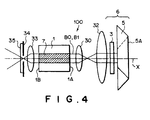
- a laser system 100 in accordance with the fourth embodiment of the present invention comprises a broad-area semiconductor laser 1 as a light source, a collimator lens 30 disposed near the right side light outlet end face 1A of the semiconductor laser 1, a cylindrical lens 32, a ⁇ /2 plate 3 which rotates the direction of polarization of the laser beam Bo passing through the cylindrical lens 32, a right-angle prism mirror 5 which is the same as that employed in the first embodiment, a collimator lens 33 disposed near the left side light outlet end face 1B of the semiconductor laser 1, a slit 34 which is disposed on a focal point of the collimator lens 33 and cuts the high order components parallel to the active layer 7 in the laser beam B2 collimated by the collimator lens 33, and a resonator mirror 35 which is disposed on the focal point of the collimator lens 33.
- the collimator lenses 30 and 33, the slit 34 and the cylindrical lens 32 form the aforesaid collimator optical system, and the ⁇ /2 plate 3 and the
- the light outlet end faces 1A and 1B of the semiconductor laser 1 are provided with antireflection coating.
- the collimator lenses 30 and 33 collimate divergent components perpendicular to the active layer 7 in the laser beam Bo and converge parallel components parallel to the active layer 7 in the laser beam Bo.
- the cylindrical lens 32 has power only in the direction parallel to the active layer 7, and only the components of the laser beam Bo passing through the collimator lens 30 which are parallel to the active layer 7 are collimated by the cylindrical lens 32.
- the focal lengths of the collimator lens 30 and the cylindrical lens 32 are set so that the beam diameters as measured in the direction perpendicular to the active layer 7 and in the direction parallel to the active layer 7 at the reflecting surface 5A of the right-angle prism mirror 5 are substantially equal to each other. Accordingly at the reflecting surface 5A, the laser beam Bo is substantially square in shape.
- the amplitude distribution in the direction parallel to the active layer 7 in the laser beam Bo radiated from the semiconductor laser 1 is forced to be in the fundamental transverse mode when the laser beam Bo is reflected by the resonator mirror optical system 6, and accordingly, amplification and oscillation of high order transverse modes are prevented, whereby only the fundamental transverse mode is amplified and caused to oscillate.
- a Fourier transform lens may be employed as in the first embodiment.
- FIG. 5A to 5C A laser system in accordance with a fifth embodiment of the present invention will be described with reference to Figures 5A to 5C, hereinbelow.
- the elements analogous to those shown in Figures 1A to 1C are given the same reference numerals and will not be described here.
- the laser system of this embodiment differs from that of the first embodiment in that a pair of prisms 10 and 11 for correcting the beam diameters of the laser beams Bo and B1 are disposed between the cylindrical lens 2 and the ⁇ /2 plate 3.
- the laser beam Bo radiated from the active layer 7 is parallel light in the direction parallel to the active layer 7 and is divergent light in the direction perpendicular to the active layer 7.
- the active layer 7 is about 100 to 200 ⁇ m in width and about 1 ⁇ m in thickness.
- the cylindrical lens 2 In order to collimate the divergent laser beam Bo into a beam having a diameter of 100 to 200 ⁇ m, the cylindrical lens 2 must be very short in focal length. However it is very difficult to produce a cylindrical lens having such a short focal length and such a cylindrical lens is very expensive if it is not impossible to produce such a cylindrical lens.
- the focal length of the cylindrical lens 2 is not so short, and the cylindrical lens 2 collimates the laser beam Bo in the direction perpendicular to the active layer 7 so that the beam diameter as measured in the direction perpendicular to the active layer 7 is larger than that as measured in the direction parallel to the active layer 7. Then the prisms 10 and 11 converge the collimated laser beam Bo in the direction perpendicular to the active layer 7 so that the beam diameter as measured in the direction perpendicular to the active layer 7 becomes substantially equal to that as measured in the direction parallel to the active layer 7.
- the beam diameter as measured in the direction perpendicular to the active layer 7 can be made substantially equal to that as measured in the direction parallel to the active layer 7 without use of an expensive cylindrical lens, whereby the laser system can manufactured at low cost.
- the beam diameter as measured in the direction perpendicular to the active layer 7 is made substantially equal to that as measured in the direction parallel to the active layer 7 by reducing the beam diameter as measured in the direction perpendicular to the active layer 7, the beam diameters may be made equal to each other by enlarging the latter.
- This can be realized, for instance, by providing between the cylindrical lens 2 and the ⁇ /2 plate 3 a negative lens which has power only in the direction parallel to the active layer 7 and a cylindrical lens which has power only in the direction parallel to the active layer 7 and collimates the laser beam diverged by the negative lens.
- FIG. 6A to 6C A laser system in accordance with a sixth embodiment of the present invention will be described with reference to Figures 6A to 6C, hereinbelow.
- the elements analogous to those shown in Figures 1A to 1C are given the same reference numerals and will not be described here.
- the laser system of this embodiment differs from that of the first embodiment in that the cylindrical lens 2 has a focal length equal to that of the cylindrical lens in the fifth embodiment and an in-mirror type Fourier transform lens 14 is employed as the Fourier transform lens.
- the beam diameter of the laser beam Bo as measured in the direction perpendicular to the active layer 7 differs from that as measured in the direction parallel to the active layer 7.
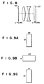
- Figure 7 shows a symmetric Fourier transform lens on the basis of which the in-mirror type Fourier transform lens shown in Figure 8 is explained.
- a symmetric Fourier transform lens comprising a pair of lens groups 20 and 21, each consisting of a concave lens and a convex lens, which are arranged symmetrically with respect to an axis of symmetry Mo so that the distance between the axis of symmetry Mo and the front focal plane M1 is equal to the distance between the axis of symmetry Mo and the back focal plane (Fourier transform plane) M2 as shown in Figure 7.
- An in-mirror type Fourier transform lens which is equivalent to the symmetric Fourier transform lens shown in Figure 7 can be formed by dividing the symmetric Fourier transform lens into two parts at the axis of symmetry Mo and providing a mirror 22 in the position of the axis of symmetry Mo with respect to one of the two parts as shown in Figure 8.
- the focal plane M4 doubles the front focal plane and the back focal plane (Fourier transform plane) of the Fourier transform lens.
- the a-plane corresponds to the focal plane M4
- the right-angle prism mirror 5 functions as the mirror 22
- the reflecting surface 5A of the prism mirror 5 i.e., the b-plane corresponds to the reflecting surface of the mirror 22.
- the focal length f of the in-mirror type Fourier transform lens 14 is set to satisfy the condition represented by the following formula (1).
- D1 x D2 K x ⁇ x f
- D1 represents the beam diameter at the a-plane of the laser beam Bo impinging upon the lens 14 as measured in the direction perpendicular to the active layer 7
- D2 represents the beam diameter at the a-plane of the laser beam Bo impinging upon the lens 14 as measured in the direction parallel to the active layer 7 (a value when the laser beam Bo oscillates in the fundamental transverse mode in the direction parallel to the active layer 7)
- K is a constant of proportionality determined depending on the shape of the beam, the aperture of the lens and the like
- ⁇ represents the wavelength of the laser beam
- f represents the focal length.
- the shape at the a-plane of the laser beam Bo before Fourier transform is like a rectangle of D1xD2 with its longer sides extending in the direction perpendicular to the active layer 7 as shown in Figure 9A
- the shape at the a-plane of the laser beam B1 after Fourier transform by the in-mirror type Fourier transform lens 14 is like a rectangle d1xd2 with its longer sides extending in the direction parallel to the active layer 7 as shown in Figure 9B. That is, the rectangle shown in Figure 9B is obtained by rotating the rectangle shown in Figure 9A by 90° .
- the shape of the laser beam is rotated by 180° about the edge 5B of the prism mirror 5 and the shape at the a-plane of the laser beam B1 after Fourier transform by the in-mirror type Fourier transform lens 14 is like a rectangle d1xd2 with its longer sides extending in the direction perpendicular to the active layer 7 as shown in Figure 9C.
- the beam diameters of the laser beam Bo before Fourier transform are equal to those of the laser beam B1 after Fourier transform by the in-mirror type Fourier transform lens 14. Accordingly, by arranging the in-mirror type Fourier transform lens 14 to satisfy the condition represented by formula (1), the beam diameters at the a-plane of the laser beam Bo as radiated from the broad-area semiconductor laser 1 can be equalized to those of the laser beam B1 entering the semiconductor laser 1.
- a laser beam including only the fundamental transverse mode can be effectively oscillated and a high quality laser beam can be obtained at a high output power, whereby the radiated laser beam can be condensed to the diffraction limit and a high power density can be obtained.
- a collimator lens may be employed in place of the cylindrical lens 2.
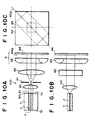
- FIG. 10A to 10C A laser system in accordance with a seventh embodiment of the present invention will be described with reference to Figures 10A to 10C, hereinbelow.
- Figures 10A to 10C the elements analogous to those shown in Figures 1A to 1C are given the same reference numerals and will not be described here.
- a laser system 100 in accordance with the seventh embodiment of the present invention comprises a broad-area semiconductor laser 1 as a light source, a collimator optical system including a collimator lens 40 disposed near the right side light outlet end face 1A of the semiconductor laser 1, a slit 41 which is disposed on a focal point of the collimator lens 40 and cuts the high order components parallel to the active layer 7 in the laser beam Bo collimated by the collimator lens 40, and a cylindrical lens 42, and a resonator mirror optical system 6 which includes a cylindrical lens 43 and a resonator mirror 44 and reflects at a predetermined reflectance the laser beam Bo passing through the cylindrical lens 42 while rotating amplitude distribution of the reflected laser beam B1 by 180° about an axis which is at 90° to the optical axis X and at 45° to a normal of the active layer 7.
- the collimator optical system formed by the collimator lens 40, the slit 41 and the cylindrical lens 42 are equivalent to the collim
- the collimator lens 40 collimates divergent components perpendicular to the active layer 7 in the laser beam Bo and converges parallel components parallel to the active layer 7 in the laser beam Bo.
- the cylindrical lens 42 has power only in the direction parallel to the active layer 7, and as shown in Figure 10A, only the components of the laser beam Bo passing through the slit 41 which are parallel to the active layer 7 are collimated by the cylindrical lens 42.
- the focal lengths of the collimator lens 40 and the cylindrical lens 42 are set so that the beam diameters as measured in the direction perpendicular to the active layer 7 and in the direction parallel to the active layer 7 of the laser beam Bo as emanating from the cylindrical lens 42 are substantially equal to each other. Accordingly, the laser beam Bo emanating from the cylindrical lens 42 and the leaser beam B1 entering the cylindrical lens 42 are both substantially square in shape.
- the resonator mirror 44 has a reflecting surface 44A provided with coating which is relatively high in reflectance.
- the cylindrical lens 43 is disposed with its longer axis 43A inclined at 45° to the direction parallel to the active layer 7 and has power in the direction inclined at 45° to the direction parallel to the active layer 7.
- the components in the laser beam Bo passing through the cylindrical lens 42 which are at 45° to the active layer 7 are focused on the reflecting surface 44A of the resonator mirror 44 and reflected by the reflector mirror 44 while being rotated by 180° about the longer axis 43A of the cylindrical lens 43. Accordingly, the amplitude distributions in the directions parallel and perpendicular to the active layer 7 in the reflected laser beam B1 respectively correspond to those in the directions perpendicular and parallel to the active layer 7 in the laser beam Bo.
- the laser beam Bo radiated from the AR-coated light outlet end face 1A of the broad-area semiconductor laser 1 is controlled so that the amplitude distribution in the direction perpendicular to the active layer is in the fundamental transverse mode. Further the laser beam Bo is parallel light in the direction parallel to the active layer 7 and is divergent light in the direction perpendicular to the active layer 7.
- the the beam diameters of the laser beam Bo as measured in the directions parallel and perpendicular to the active layer 7 are made to be equal to each other by the collimator lens 40 and the cylindrical lens 42. Accordingly, the beam diameters as measured in the direction perpendicular to the active layer 7 and in the direction parallel to the active layer 7 of the laser beam Bo as emanating from the cylindrical lens 42 are substantially equal to each other.
- the laser beam Bo thus shaped enters the cylindrical lens 43.
- the laser beam Bo which enters the cylindrical lens 43 is caused to form an image on the reflecting surface 44A of the resonator mirror 44 and is reflected by the reflecting surface 44A. Since the longer axis 43A of the cylindrical lens 43 is at 45° to the direction parallel to the active layer 7, the amplitude distribution of the laser beam Bo is inverted by 180° about the longer axis 43A. Further the direction of polarization of the reflected laser beam B1 is equal to that of the laser beam Bo before reflection as described above.
- the components of the laser beam B1 reflected by the resonator mirror 44 which are at 45° to the direction parallel to the active layer 7 are collimated by the cylindrical lens 43, and accordingly the laser beam B1 entering the cylindrical lens 42 has the same diameter in the direction perpendicular to the active layer 7 and in the direction parallel to the active layer 7. Further the amplitude distributions of the laser beam B1 in the directions parallel and perpendicular to the active layer 7 respectively correspond to those of the laser beam Bo in the directions perpendicular and parallel to the active layer 7.
- the laser beam B1 is caused to form an image on the light outlet end face 1A of the semiconductor laser 1 by the cylindrical lens 42 and the collimator leans 40.
- the amplitude distribution controlled to the fundamental transverse mode by the active layer 7 has been made to be an amplitude distribution in the direction parallel to the active layer 7. That is, though the amplitude distribution controlled to the fundamental transverse mode by the active layer 7 in the laser beam Bo radiated from the light outlet end face 1A is an amplitude distribution in the direction perpendicular to the active layer 7, the amplitude distribution in the fundamental transverse mode in the laser beam B1 impinging upon the end face 1A is in the direction parallel to the active layer 7. Further since the beam diameter of the laser beam B1 is unchanged before and after the laser beam B1 passing through the Fourier transform lens 4, the laser beam B1 impinging upon the end face 1A of the semiconductor laser 1 is effectively caused to form an image on the active layer 7.
- the amplitude distribution in the direction parallel to the active layer 7 in the laser beam Bo radiated from the semiconductor laser 1 is forced to be in the fundamental transverse mode when the laser beam Bo is reflected by the resonator mirror optical system 6, and accordingly, amplification and oscillation of high order transverse modes are prevented, whereby only the fundamental transverse mode is amplified and caused to oscillate.
- a Fourier transform lens may be employed as in the first embodiment.
- the collimator lens system is formed by a collimator lens 40, a slit 41 and a cylindrical lens 42 as in the third embodiment, the collimator lens system is may be formed as in the first, fourth, fifth or sixth embodiment.
- the resonator mirror optical system 6 is disposed on the side of the right side light outlet end face 1A of the broad-area semiconductor laser 1 with the left side light outlet end face 1B of the semiconductor laser 1 provided with a LR coating
- a resonator mirror optical system similar to that employed in one of the first to seventh embodiments may be provided also on the side of the left side light outlet end face 1B of the semiconductor laser 1 instead of providing the end face 1B with a LR coating.
- a Fourier transform lens is employed in order to prevent loss of the laser beams Bo and B1
- a collimator lens may be employed in place of the Fourier transform lens.
Landscapes
- Physics & Mathematics (AREA)
- General Physics & Mathematics (AREA)
- Optics & Photonics (AREA)
- Condensed Matter Physics & Semiconductors (AREA)
- Electromagnetism (AREA)
- Semiconductor Lasers (AREA)
Applications Claiming Priority (2)
| Application Number | Priority Date | Filing Date | Title |
|---|---|---|---|
| JP12330198 | 1998-05-06 | ||
| JP12330198A JP3387824B2 (ja) | 1998-05-06 | 1998-05-06 | レーザ装置 |
Publications (3)
| Publication Number | Publication Date |
|---|---|
| EP0955707A2 true EP0955707A2 (de) | 1999-11-10 |
| EP0955707A3 EP0955707A3 (de) | 2006-04-12 |
| EP0955707B1 EP0955707B1 (de) | 2008-01-02 |
Family
ID=14857160
Family Applications (1)
| Application Number | Title | Priority Date | Filing Date |
|---|---|---|---|
| EP99108879A Expired - Lifetime EP0955707B1 (de) | 1998-05-06 | 1999-05-05 | Lasersystem |
Country Status (4)
| Country | Link |
|---|---|
| US (1) | US6163558A (de) |
| EP (1) | EP0955707B1 (de) |
| JP (1) | JP3387824B2 (de) |
| DE (1) | DE69937857T2 (de) |
Cited By (2)
| Publication number | Priority date | Publication date | Assignee | Title |
|---|---|---|---|---|
| WO2006056949A1 (en) * | 2004-11-29 | 2006-06-01 | Koninklijke Philips Electronics N.V. | Radiation beam source device |
| WO2020078197A1 (zh) * | 2018-10-15 | 2020-04-23 | 中国科学院理化技术研究所 | 一种半导体激光器 |
Families Citing this family (12)
| Publication number | Priority date | Publication date | Assignee | Title |
|---|---|---|---|---|
| US6738396B2 (en) | 2001-07-24 | 2004-05-18 | Gsi Lumonics Ltd. | Laser based material processing methods and scalable architecture for material processing |
| US7065121B2 (en) * | 2001-07-24 | 2006-06-20 | Gsi Group Ltd. | Waveguide architecture, waveguide devices for laser processing and beam control, and laser processing applications |
| AU2003253359A1 (en) * | 2002-09-02 | 2004-03-19 | Hentze-Lissotschenko Patentverwaltungs Gmbh And Co. Kg | Semiconductor laser device |
| DE602005010847D1 (de) * | 2004-05-05 | 2008-12-18 | Presstek Inc | Laserabbildung von kunstgraphik mit verkürzten laserresonatoren und verbesserter leistungsfähigkeit |
| JP2006080412A (ja) * | 2004-09-13 | 2006-03-23 | Sony Corp | レーザシステム |
| US7376169B2 (en) * | 2005-03-07 | 2008-05-20 | Joseph Reid Henrichs | Optical phase conjugation laser diode |
| US7370760B2 (en) * | 2005-04-15 | 2008-05-13 | Kimberly-Clark Worldwide, Inc. | Package that includes a plurality of disposable absorbent articles |
| JP2009289990A (ja) * | 2008-05-29 | 2009-12-10 | Hamamatsu Photonics Kk | レーザ光源 |
| JP4871326B2 (ja) * | 2008-05-29 | 2012-02-08 | 浜松ホトニクス株式会社 | レーザ光源 |
| JPWO2016080252A1 (ja) * | 2014-11-20 | 2017-08-31 | カナレ電気株式会社 | 外部共振器型半導体レーザ |
| CN215377956U (zh) * | 2021-06-21 | 2021-12-31 | 苏州旭创科技有限公司 | 外腔激光器 |
| CN118920269B (zh) * | 2024-07-16 | 2026-04-03 | 浙江法拉第激光科技有限公司 | 基于五角棱镜旋转的可调谐式外腔半导体激光器 |
Family Cites Families (6)
| Publication number | Priority date | Publication date | Assignee | Title |
|---|---|---|---|---|
| US5050179A (en) * | 1989-04-20 | 1991-09-17 | Massachusetts Institute Of Technology | External cavity semiconductor laser |
| US5018153A (en) * | 1990-02-23 | 1991-05-21 | Hughes Aircraft Company | Method and apparatus for correcting amplitude variation in electro-optic laser systems |
| JP2685969B2 (ja) * | 1990-08-29 | 1997-12-08 | 沖電気工業株式会社 | 第2高調波発生装置 |
| US5185752A (en) * | 1992-02-18 | 1993-02-09 | Spectra Diode Laboratories, Inc. | Coupling arrangements for frequency-doubled diode lasers |
| US5452312A (en) * | 1993-10-18 | 1995-09-19 | Matsushita Electric Industrial Co., Ltd. | Short-wavelength laser light source and optical information processing aparatus |
| US5513196A (en) * | 1995-02-14 | 1996-04-30 | Deacon Research | Optical source with mode reshaping |
-
1998
- 1998-05-06 JP JP12330198A patent/JP3387824B2/ja not_active Expired - Fee Related
-
1999
- 1999-05-05 US US09/305,694 patent/US6163558A/en not_active Expired - Lifetime
- 1999-05-05 DE DE69937857T patent/DE69937857T2/de not_active Expired - Lifetime
- 1999-05-05 EP EP99108879A patent/EP0955707B1/de not_active Expired - Lifetime
Cited By (2)
| Publication number | Priority date | Publication date | Assignee | Title |
|---|---|---|---|---|
| WO2006056949A1 (en) * | 2004-11-29 | 2006-06-01 | Koninklijke Philips Electronics N.V. | Radiation beam source device |
| WO2020078197A1 (zh) * | 2018-10-15 | 2020-04-23 | 中国科学院理化技术研究所 | 一种半导体激光器 |
Also Published As
| Publication number | Publication date |
|---|---|
| DE69937857D1 (de) | 2008-02-14 |
| EP0955707B1 (de) | 2008-01-02 |
| JP3387824B2 (ja) | 2003-03-17 |
| DE69937857T2 (de) | 2009-01-02 |
| US6163558A (en) | 2000-12-19 |
| EP0955707A3 (de) | 2006-04-12 |
| JPH11317562A (ja) | 1999-11-16 |
Similar Documents
| Publication | Publication Date | Title |
|---|---|---|
| US4656641A (en) | Laser cavity optical system for stabilizing the beam from a phase locked multi-emitter broad emitter laser | |
| US6212216B1 (en) | External cavity micro laser apparatus | |
| EP0955707B1 (de) | Lasersystem | |
| EP0310241B1 (de) | Transversal gepumpter modenangepasster Festkörperlaser mit hohem Wirkungsgrad | |
| JP3265173B2 (ja) | 固体レーザ装置 | |
| US4894839A (en) | High efficiency mode-matched solid-state laser with transverse pumping | |
| US20020154673A1 (en) | High-power blue and green light laser generation from high-powered diode lasers | |
| CA2049943A1 (en) | External cavity semiconductor laser | |
| EP0508406B1 (de) | Laserstrahlerzeugende Vorrichtung | |
| CA2329089C (en) | Fiber grating feedback stabilization of broad area laser diode | |
| JPWO2019155668A1 (ja) | 半導体レーザ装置 | |
| US6920160B2 (en) | Laser resonators comprising mode-selective phase structures | |
| CN100438236C (zh) | 光放大装置、光源、其组合以及用于放大光学辐射的方法 | |
| EP1490934A2 (de) | Lasersystem | |
| US6625194B1 (en) | Laser beam generation apparatus | |
| US4868515A (en) | Narrow-bandwidth unstable laser resonator | |
| EP0831567B1 (de) | Plattenförmiger laseroszillator | |
| US6385229B1 (en) | Laser | |
| US7142568B2 (en) | High-power blue and green light laser generation from high-powered diode lasers | |
| US5097477A (en) | Laser diode pumped multiple rod ring laser allowing combination of multiple pump sources | |
| WO1998015994A1 (en) | External cavity micro laser apparatus | |
| US6314120B1 (en) | Semiconductor laser pumped solid state laser | |
| JPH0661583A (ja) | 半導体レーザ | |
| JPH07106669A (ja) | レーザー共振器 | |
| JP2962561B2 (ja) | レーザダイオード励起固体レーザ装置 |
Legal Events
| Date | Code | Title | Description |
|---|---|---|---|
| PUAI | Public reference made under article 153(3) epc to a published international application that has entered the european phase |
Free format text: ORIGINAL CODE: 0009012 |
|
| AK | Designated contracting states |
Kind code of ref document: A2 Designated state(s): AT BE CH CY DE DK ES FI FR GB GR IE IT LI LU MC NL PT SE |
|
| AX | Request for extension of the european patent |
Free format text: AL;LT;LV;MK;RO;SI |
|
| PUAL | Search report despatched |
Free format text: ORIGINAL CODE: 0009013 |
|
| AK | Designated contracting states |
Kind code of ref document: A3 Designated state(s): AT BE CH CY DE DK ES FI FR GB GR IE IT LI LU MC NL PT SE |
|
| AX | Request for extension of the european patent |
Extension state: AL LT LV MK RO SI |
|
| RIC1 | Information provided on ipc code assigned before grant |
Ipc: H01S 3/00 20060101AFI20060222BHEP |
|
| 17P | Request for examination filed |
Effective date: 20061010 |
|
| 17Q | First examination report despatched |
Effective date: 20061116 |
|
| AKX | Designation fees paid |
Designated state(s): DE FR GB |
|
| RAP1 | Party data changed (applicant data changed or rights of an application transferred) |
Owner name: FUJIFILM CORPORATION |
|
| GRAP | Despatch of communication of intention to grant a patent |
Free format text: ORIGINAL CODE: EPIDOSNIGR1 |
|
| RIC1 | Information provided on ipc code assigned before grant |
Ipc: H01S 5/14 20060101AFI20070611BHEP |
|
| GRAS | Grant fee paid |
Free format text: ORIGINAL CODE: EPIDOSNIGR3 |
|
| GRAA | (expected) grant |
Free format text: ORIGINAL CODE: 0009210 |
|
| AK | Designated contracting states |
Kind code of ref document: B1 Designated state(s): DE FR GB |
|
| REG | Reference to a national code |
Ref country code: GB Ref legal event code: FG4D |
|
| REF | Corresponds to: |
Ref document number: 69937857 Country of ref document: DE Date of ref document: 20080214 Kind code of ref document: P |
|
| ET | Fr: translation filed | ||
| PLBE | No opposition filed within time limit |
Free format text: ORIGINAL CODE: 0009261 |
|
| STAA | Information on the status of an ep patent application or granted ep patent |
Free format text: STATUS: NO OPPOSITION FILED WITHIN TIME LIMIT |
|
| 26N | No opposition filed |
Effective date: 20081003 |
|
| PGFP | Annual fee paid to national office [announced via postgrant information from national office to epo] |
Ref country code: GB Payment date: 20130501 Year of fee payment: 15 |
|
| PGFP | Annual fee paid to national office [announced via postgrant information from national office to epo] |
Ref country code: FR Payment date: 20130531 Year of fee payment: 15 |
|
| PGFP | Annual fee paid to national office [announced via postgrant information from national office to epo] |
Ref country code: DE Payment date: 20140430 Year of fee payment: 16 |
|
| GBPC | Gb: european patent ceased through non-payment of renewal fee |
Effective date: 20140505 |
|
| REG | Reference to a national code |
Ref country code: FR Ref legal event code: ST Effective date: 20150130 |
|
| PG25 | Lapsed in a contracting state [announced via postgrant information from national office to epo] |
Ref country code: GB Free format text: LAPSE BECAUSE OF NON-PAYMENT OF DUE FEES Effective date: 20140505 Ref country code: FR Free format text: LAPSE BECAUSE OF NON-PAYMENT OF DUE FEES Effective date: 20140602 |
|
| REG | Reference to a national code |
Ref country code: DE Ref legal event code: R119 Ref document number: 69937857 Country of ref document: DE |
|
| PG25 | Lapsed in a contracting state [announced via postgrant information from national office to epo] |
Ref country code: DE Free format text: LAPSE BECAUSE OF NON-PAYMENT OF DUE FEES Effective date: 20151201 |